1
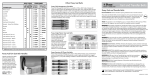
EDG-6528
8-Port Industrial 10/100 Mbps
Ethernet Switch
User Manual
Copyright
The documentation and the software included with this product are copyrighted 2005 by Advantech Co., Ltd. All rights are reserved. Advantech
Co., Ltd. reserves the right to make improvements in the products
described in this manual at any time without notice. No part of this manual may be reproduced, copied, translated or transmitted in any form or
by any means without the prior written permission of Advantech Co., Ltd.
Information provided in this manual is intended to be accurate and reliable. However, Advantech Co., Ltd. assumes no responsibility for its use,
nor for any infringements of the rights of third parties, which may result
from its use.
Part No. 2003652802
3rd Edition
Printed in Taiwan
July 2005
EDG-6528 User Manual
ii
Product Warranty (2 years)
Advantech warrants to you, the original purchaser, that each of its products will be free from defects in materials and workmanship for two years
from the date of purchase.
This warranty does not apply to any products which have been repaired or
altered by persons other than repair personnel authorized by Advantech,
or which have been subject to misuse, abuse, accident or improper installation. Advantech assumes no liability under the terms of this warranty as
a consequence of such events.
Because of Advantech’s high quality-control standards and rigorous testing, most of our customers never need to use our repair service. If an
Advantech product is defective, it will be repaired or replaced at no
charge during the warranty period. For out-of-warranty repairs, you will
be billed according to the cost of replacement materials, service time and
freight. Please consult your dealer for more details.
If you think you have a defective product, follow these steps:
1.
Collect all the information about the problem encountered. (For
example, CPU speed, Advantech products used, other hardware
and software used, etc.) Note anything abnormal and list any
onscreen messages you get when the problem occurs.
2.
Call your dealer and describe the problem. Please have your manual, product, and any helpful information readily available.
3.
If your product is diagnosed as defective, obtain an RMA (return
merchandize authorization) number from your dealer. This allows
us to process your return more quickly.
4.
Carefully pack the defective product, a fully-completed Repair and
Replacement Order Card and a photocopy proof of purchase date
(such as your sales receipt) in a shippable container. A product
returned without proof of the purchase date is not eligible for warranty service.
5.
Write the RMA number visibly on the outside of the package and
ship it prepaid to your dealer.
iii
CE
This product has passed the CE test for environmental specifications. Test
conditions for passing included the equipment being operated within an
industrial enclosure. In order to protect the product from being damaged
by ESD (Electrostatic Discharge) and EMI leakage, we strongly recommend the use of CE-compliant industrial enclosure products.
FCC Class A
This equipment has been tested and found to comply with the limits for a
Class A digital device, pursuant to Part 15 of the FCC Rules. These limits
are designed to provide reasonable protection against harmful interference when the equipment is operated in a commercial environment. This
equipment generates, uses and can radiate radio frequency energy and, if
not installed and used in accordance with the instruction manual, may
cause harmful interference to radio communications. Operation of this
equipment in a residential area is likely to cause harmful interference in
which case the user will be required to correct the interference at his own
expense.
Technical Support and Assistance
Step 1. Visit the Advantech web site at www.advantech.com/support
where you can find the latest information about the product.
Step 2. Contact your distributor, sales representative, or Advantech's customer service center for technical support if you need additional
assistance. Please have the following information ready before
you call:
- Product name and serial number
- Description of your peripheral attachments
- Description of your software (operating system, version, application software, etc.)
- A complete description of the problem
- The exact wording of any error messages
Document Feedback
To assist us in making improvements to this manual, we would welcome
comments and constructive criticism. Please send all such - in writing to:
[email protected]
EDG-6528 User Manual
iv
Contents
Chapter
1 Introduction ..................................................... 2
1.1
1.2
1.3
1.4
1.5
1.6
Chapter
Features ............................................................................. 2
Feature Summary .............................................................. 3
Specifications .................................................................... 4
Packing List....................................................................... 4
Ordering Information ........................................................ 4
Safety Precaution............................................................... 5
2 Installation ....................................................... 8
2.1
LED Definitions ................................................................ 8
2.2
Dimensions........................................................................ 9
2.3
Mounting ......................................................................... 10
Table 2.1:EDG-6528 LED Definition ........................... 8
Figure 2.1:EDG-6528 Front Panel and Dimension ...... 9
2.3.1
2.3.2
2.3.3
2.4
2.5
Panel Mounting ............................................................ 10
Figure 2.2:Attach the Bracket to the EDG-6528 with Six
Screws .............................................................. 10
Figure 2.3:Panel Mounting ......................................... 10
DIN-rail Mounting ....................................................... 11
Figure 2.4:Attach the DIN-rail Mounting Kit to EDG6528 with Six Screws ...................................... 11
Figure 2.5:DIN-rail Mounting. .................................... 11
DIN-rail Dismounting .................................................. 12
Figure 2.6:DIN-rail Dismounting ................................ 12
Network Connections...................................................... 13
2.4.1
2.4.2
Connection to Devices ................................................. 13
Connection to Other Hubs or Switches ........................ 13
Power Connections.......................................................... 14
Figure 2.7:Pin Assignment of EDG-6528’s Power Connector .............................................................. 14
v
EDG-6528 User Manual
vi
CHAPTER
1
2
Introduction
Sections include:
• Features
• Specifications
• Packing List
• Ordering Information
• Safety Precaution
Chapter 1 Introduction
1.1 Features
The EDG-6528 is an industrial-grade Ethernet switch for fast and costeffective expansion of industrial Ethernet networks. The EDG-6528 has
eight 10/100 Mbps Ethernet ports to connect up to eight Ethernet devices.
Moreover, EDG-6528 has industrial-grade design that assures high reliability and stability. Therefore, EDG-6528 is an excellent solution for
industrial environments with Ethernet networking, such as: semi-conductor factories, inventory control environments, assembly lines and production facilities.
High-Speed Transmission
The EDG-6528 includes a switch controller that can automatically sense
transmission speeds. (10/100 Mbps) The RJ-45 interface can also be autodetected, so MDI or MDI-X is automatically selected and a crossover
cable is not required. All Ethernet ports have memory buffers that support
the store-and-forward mechanism. This assures that data is properly
transmitted.
Dual Power Inputs (does not include EDG-6528L)
To reduce the risk of power failure, the EDG-6528 provides dual power
inputs. If there is a power failure, EDG-6528 will automatically switch to
the secondary power input.
Flexible Mounting
EDG-6528 is extremely compact and can be mounted on a DIN-rail or a
panel, so it is suitable for any space-constrained environment.
Advanced Protection for Power line and Ethernet Port
The power line of EDG-6528 supports up to 3000 VDC surge protection,
which secure equipment against unregulated voltage and make systems
safer and more reliable. Meanwhile, 4000 V DC ESD protection for
Ethernet ports (not including EDG-6528L) make EDG-6528 more suitable for harsh environments.
EDG-6528 User Manual
2
Wide Operating Temperature Range
The operating temperature of the EDG-6528 is between 0 and 70° C, and
the EDG-6528I can operate between -40 and 85° C. With such a wide
range you can use the EDG-6528 in some of the harshest industrial environments that exist.
Easy to Trouble-Shoot
LED indicators make troubleshooting quick and easy. Each port has
LEDs that display the link status, power failure, and port activity for
immediate on-site diagnosis. (See 2.1)
1.2 Feature Summary
• Provides 8 x 10/100 Mbps Ethernet ports with RJ-45 connector
• Supports dual power inputs (not including EDG-6528L)
• Supports full/half duplex flow control
• Supports MDI/MDI-X auto crossover
• Provides broadcast storm protection
• Embedded with a switch controller, supports auto-negotiation
• Embedded with the memory buffer, supports store-and-forward transmission
• Supports +12 ~ 48 VDC voltage
• Provides 3000 VDC surge protection for power line
• Provides 4000VDC ESD protection for Ethernet Ports
(not including EDG-6528L)
• Provides flexible mounting: DIN rail and panel mounting
• Supports wide-range operating temperature
• 128 KB of SRAM on chip for frame buffering
• Integrated address Look-Up Engine, supports 1K absolute MAC
addresses
3
Chapter 1
1.3 Specifications
• Interfaces: Network 10/100Base-Tx standard
• Ports: 8 x 10/100 Mbps (RJ-45)
• Connectors: 8 x RJ-45
• Compatibility: IEEE 802.3, IEEE 802.3u
• Surge Protection: 3000 VDC (Power)
• ESD Protection: 4000 V DC (Ethernet)(not including EDG-6528L)
• LEDs: Power, LNK/ACT, 10/100 Mbps
• Transmission Distance: 100 m (Ethernet)
• Power Requirement: Unregulated 12~48 VDC
• Power Consumption: Max. 3.1 W
• Case: Aluminum with mounting bracket
• Mounting: DIN-rail, panel
• Operating Temperature: EDG-6528I: -40 ~ 85° C
EDG-6528 and EDG-6528L: 0 ~ 70° C
• Operating Humidity: 20~95% (non-condensing)
• SRAM on chip for frame buffering: 128 KB
• Integrated address Look-Up Engine, supports 1K absolute MAC
addresses.
1.4 Packing List
• EDG-6528 8-Port 10/100 Ethernet Switch
• INET CD-ROM
• DIN real mounting adapter
• Panel mounting bracket
1.5 Ordering Information
• EDG-6528 8-port Industrial 10/100 Mbps Ethernet Switch
• EDG-6528L 8-port Industrial Unmanaged Ethernet Switch
• EDG-6528I 8-port Industrial 10/100 Mbps Ethernet Switch with Wide
Operating Temperature
EDG-6528 User Manual
4
1.6 Safety Precaution
Attention! If DC voltage is supplied by an external circuit, please use a
protection device on the power supply input.
5
Chapter 1
EDG-6528 User Manual
6
CHAPTER
2
2
Installation
In this chapter, you will be given an
overview of the EDG-6528 installation
procedure.
Sections include:
• LED Definitions
• Dimensions
• Mounting
• Network Connections
• Power Connections
Chapter 2 Installation
2.1 LED Definitions
There are network status LEDs located on the front panel of EDG-6528,
each with its own specific meaning..
Table 2.1: EDG-6528 LED Definition
LED
Color
PWR
Green
P1
(EDG-6528L
does not have
this LED)
Green
P2
(EDG-6528L
does not have
this LED)
Green
FAULT
(EDG-6528L
does not have
this LED)
Red
Link (Port 1~8)
Orange
Description
On
Power is on
Off
Power is off
On
Power input 1 is active
Off
Power input 1 is inactive
On
Power input 2 is active
Off
Power input 2 is inactive
On
Power input 1 or Power input 2
have failed
Off
Power input 1 and Power input 2
are active
On
Networking
Flash Networking is active
10/100 (Port 1~ 8) Green
EDG-6528 User Manual
Off
No Networking
On
Link to 100M bps
Off
Link to 10M bps
8
2.2 Dimensions
Figure 2.1: EDG-6528 Front Panel and Dimension
9
Chapter 2
2.3 Mounting
2.3.1 Panel Mounting
• Attach the bracket to the EDG-6528 with four screws.
• Place the EDG-6528 against the panel or wall, and fasten it by using
two screws in the bracket’s holes.
Figure 2.2: Attach the Bracket to the EDG-6528 with Six Screws
Figure 2.3: Panel Mounting
EDG-6528 User Manual
10
2.3.2 DIN-rail Mounting
1.
Attach the DIN-rail mounting kit to the EDG-6528 with six screws.
Figure 2.4: Attach the DIN-rail Mounting Kit to EDG-6528 with Six Screws
2.
Snap the EDG-6528 onto the DIN rail to attach it.
Figure 2.5: DIN-rail Mounting.
11
Chapter 2
2.3.3 DIN-rail Dismounting
Use a flat screwdriver to lift the DIN rail’s attachment bracket up. This
will release the EDG-6528 from the Din-rail. Then pull the EDG-6528
down to dismount it.
Figure 2.6: DIN-rail Dismounting
EDG-6528 User Manual
12
2.4 Network Connections
2.4.1 Connection to Devices
Each of the switch’s twisted-pair ports can be used to connect a station or
another device. Use a straight-through twisted-pair cable with RJ-45 connectors on both ends. A twisted-pair cable extended from a twisted-pair
port is called a “twisted-pair segment,” and it can be up to 100 meters
long.
You can connect any RJ-45(MDI-X) station port on the switch to any
device that uses a standard network interface such as a workstation or
server.
2.4.2 Connection to Other Hubs or Switches
EDG-6528 has 8 RJ-45 ports that support connection to 10 Mbps Ethernet or 100 Mbps Fast Ethernet, and half or fullduplex operation. EDG6528 can be connected to other hubs or switches via a two-pair straight
through cable or a crossover cable.
The connection can be made from any ports on EDG-6528 (MDIX) to
other Hubs or Switches either by MDI-X port or the uplink MDI port.
EDG-6528 supports auto crossover to make it easier to setup your network. You can connect any RJ-45(MDI-X) station port on the switch to
any device such as a switch, bridge or router.
13
Chapter 2
2.5 Power Connections
EDG-6528 and EDG-6528I support two individual power inputs (P1/P2);
it will switch to another power input if one power input fails.
Pin
Description
+Vs
Power input 1 (Range: +12~48VDC)
+Vs*
Power input 2 (Range: +12~48VDC)
GND
Power ground
Relay out (EDG-6528L does not have this function)
You can connect to an alarm such as an indicator, buzzer or
other signaling equipment by EDG-6528’s relay output. The
relay opens if power input 1 or power input 2 fails.
FAULT
+V s +V s * GND
(Relay Output)
+
-
12~48V DC
(Power Input 2)
+
-
Figure 2.7: Pin Assignment of EDG-6528’s Power Connector
EDG-6528 User Manual
14