1
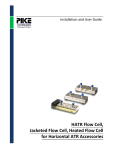
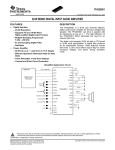
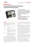
NIS54xxGEVB NIS54xx Evaluation Board User’s Manual eFuse test board with multiple subcircuits for evaluation of overvoltage protection, overcurrent protection, controlled slew rate, and thermal shutdown features EVAL BOARD USER’S MANUAL Introduction Engineers developing a varied array of systems utilize sophisticated integrated eFuses to serve a variety of purposes. They may be found connected to 3.3, 5, and 12 V power rails and have many interesting features. The primary features of eFuses are: Overvoltage clamping Adjustable current limiting Enable/Fault control Thermal shutdown Controllable slew rate This evaluation board has many features which make it simple to observe the functionality and performance of the new NIS54xx line of eFuses: Figure 1: The NIS545xGEVB evaluation board © Semiconductor Components Industries, LLC, 2015 April, 2015 − Rev. 2 Multiple connectors available for all eFuse pins (VCC, GND, enable, ILIM, dv/dt) Input and output capacitors A pushbutton switch and a MOSFET connect the enable pin to GND or float it as needed Green and yellow LEDs to indicate whether the eFuse enable pin voltage is high (device enabled) or low (device disabled) Three current limit resistor options available directly on the board (10, 18, 50 Ω) Two load resistor options (5 and 10 Ω) on the board A pushbutton switch to short circuit the load, featuring an indicator LED which is on when the output voltage is high during normal operation An easy means of connecting an external copper heat sink for thermal evaluation Kelvin or direct sensing options via the jumper between pin 1 and 2 for the NIS54xx NIS54xxGEVB Figure 2: Schematic for the evaluation board. The user’s manual is divided into two sections. The first section is for the NIS5431 3.3 V series of devices. The second section covers the NIS545x 5 V series of devices. For these devices ensure that J1 is in the “54xx” position. Figure 3: Features of the evaluation board. http://onsemi.com NIS54xxGEVB NIS5431 Overvoltage Protection Connect the eFuse to a variable DC power supply. Place jumpers J2 (10 Ω), J1 (5431), J4, J8, and J13. Turn the power supply from 3.3 to 10 V to observe the overvoltage protection circuit in operation. The input voltage will rise, but the output voltage will be maintained at the Vclamp level of about 3.8 V. After conducting 1.1 A with a voltage drop of 6.2 V, the device will reach its thermal shutdown point and latch off. The green indicator LEDs will turn off and the yellow “fault” indicator LED will be on. An auto-retry eFuse (MT2 part number suffix) does not latch and automatically cycles the enable pin. For auto-retry eFuses the demo board’s green and yellow indicator enable pin indicator LEDs will flash as the enable pin cycles between states. Figure 4: In this test, the input voltage (blue trace) is brought to 10 V. The output voltage (red trace) is clamped at 3.8 V. After some time the device enters thermal shutdown. http://onsemi.com NIS54xxGEVB NIS5431 Reset from Thermal Shutdown Continue with jumpers J2 (10 Ω), J1 (5431), J4, J8, and J13. Once the eFuse reaches thermal shutdown the enable pin will fall to 1.4 V. Return the power supply to 3.3 V and press the blue button to reset the eFuse. An auto-retry eFuse (MT2 part number suffix) does not latch and automatically cycles the enable pin. For auto-retry eFuses the demo board’s green and yellow indicator enable pin indicator LEDs will flash as the enable pin cycles between states. Figure 5: This test shows how the enable pin is used to reset the device after a thermal shutdown event. After pressing the blue button the enable pin falls to 0 V and then comes to about 3.3 V after releasing the blue button. At that point the eFuse turns on. An auto-retry device will reset automatically from thermal shutdown and pressing the blue button is not necessary. http://onsemi.com NIS54xxGEVB NIS5431 Overcurrent Protection Continue with jumpers J2 (10 Ω), J1 (5431), J4, J8, and J13. With VCC set to 3.3 V, press the large green button to short circuit the output. A power supply capable of supplying more than 3 A is recommended. The mechanical switch will bounce, but the eFuse will have no issue responding to this disturbance. It will respond to the fault within 10 μs and the current will be limited to the short circuit current limit level. After some time the device will enter thermal shutdown due to the high current and voltage between VCC and source (output voltage) pins. An auto-retry eFuse (MT2 part number suffix) does not latch and automatically cycles the enable pin. For auto-retry eFuses the demo board’s green and yellow indicator enable pin indicator LEDs will flash as the enable pin cycles between states. Figure 6: This is a demonstration of the current limiting circuit. The eFuse responds quickly to the short circuit event and begins conducting at the short circuit current limit. http://onsemi.com NIS54xxGEVB NIS5431 Controlled slew rate Continue with jumpers J2 (10 Ω), J1 (5431), J4, J8, and J13. Perform this test with and without the J6 jumper in place to observe how the duration of the controlled slew rate changes. When J6 is in place, the slew rate will be longer because a capacitor is connected between the dv/dt pin and GND. With VCC set to 3.3 V, press and release the blue button to see the eFuse turn on with a controlled output voltage slew rate. Figure 7. This is a demonstration of the controlled slew rate circuit with J6 in place. Without J6 in place, the slew rate will be lower. http://onsemi.com NIS54xxGEVB NIS5431 Hot Plug Power On Use jumpers J2 (10 Ω), J1 (5431), J4, J6, J8, and J13. Manually take the 3.3 V power cable and plug it into the demo board. Observe that the eFuse turns on with no issue and the output voltage rises in a controlled fashion. Figure 8. This shows a standard hot plug test. The input cable is manually plugged into the board and the output voltage rises slowly to minimize inrush current. http://onsemi.com NIS54xxGEVB NIS5431 Hot Plug Power On into a Short Circuit Use jumpers J2 (10 Ω), J1 (5431), J4, J6, J8, and J13. Short circuit the output and manually take the 3.3 V power cable and plug it into the demo board. The eFuse briefly turns on and conducts at the short circuit current limit level. After some time the devices reaches the thermal shutdown level and latches off. An auto-retry eFuse (MT2 part number suffix) does not latch and automatically cycles the enable pin. For auto-retry eFuses the demo board’s green and yellow indicator enable pin indicator LEDs will flash as the enable pin cycles between states. Figure 9. This shows a hot plug test into a short circuit. The input cable is manually plugged into the board. The eFuse limits the current, enters thermal shutdown, and latches off. Auto-retry devices such as the NIS5450MT2 will not latch off. http://onsemi.com NIS54xxGEVB NIS545x Overvoltage Protection Connect the eFuse to a variable DC power supply. Place jumpers J2 (10 Ω), J1 (545x), J4, and J13. Turn the power supply from 5 to 10 V to observe the overvoltage protection circuit in operation. The input voltage will rise, but the output voltage will be maintained at the Vclamp level of about 6 V. After conducting 1.5 A with a voltage drop of 4 V, the eFuse will reach its thermal shutdown point and latch off. The green indicator LEDs will turn off and the yellow “fault” indicator LED will be on. An auto-retry eFuse (MT2 part number suffix) does not latch and automatically cycles the enable pin. For auto-retry eFuses the demo board’s green and yellow indicator enable pin indicator LEDs will flash as the enable pin cycles between states. Figure 10: In this test, the input voltage (blue trace) is brought to 10 V. The output voltage (red trace) is clamped at about 6 V. After some time the device enters thermal shutdown. http://onsemi.com NIS54xxGEVB NIS545x Reset from Thermal Shutdown Continue with jumpers J2 (10 Ω), J1 (545x), J4, and J13. Once the eFuse reaches thermal shutdown the enable pin falls to 1.4 V. Return the power supply to 5 V and press the blue button to reset the eFuse. An auto-retry eFuse (MT2 part number suffix) does not latch and automatically cycles the enable pin. For auto-retry eFuses the demo board’s green and yellow indicator enable pin indicator LEDs will flash as the enable pin cycles between states. Figure 11: This test shows how the enable pin is used to reset the device after a thermal shutdown event. After pressing the blue button the enable pin falls to 0 V and then comes to about 3.3 V after releasing the blue button. At that point the efuse turns on. An auto-retry device such as the NIS5450MT2 will reset automatically from thermal shutdown and pressing the blue button is not necessary. http://onsemi.com NIS54xxGEVB NIS545x Overcurrent Protection Continue with jumpers J2 (10 Ω), J1 (545x), J4, and J13. With VCC set to 5 V, press the large green button to short circuit the output. A power supply capable of supplying more than 3 A is recommended. The mechanical switch will bounce, but the eFuse will have no issue responding to this disturbance. It will respond to the fault within 10 μs and the current will be limited to the short circuit current limit level. After some time the device will enter thermal shutdown due to the high current and voltage between VCC and source (output voltage) pins. An auto-retry eFuse (MT2 part number suffix) does not latch and automatically cycles the enable pin. For auto-retry eFuses the demo board’s green and yellow indicator enable pin indicator LEDs will flash as the enable pin cycles between states. Figure 12: This is a demonstration of the current limiting circuit. The eFuse responds quickly to the short circuit event and begins conducting at the short circuit current limit. http://onsemi.com NIS54xxGEVB NIS545x Controlled slew rate Continue with jumpers J2 (10 Ω), J1 (545x), J4, and J13. Perform this test with and without the J6 jumper in place to observe how the duration of the controlled slew rate changes. When J6 is in place, the slew rate will be longer because a capacitor is connected between the dv/dt pin and GND. With VCC set to 5 V, press and release the blue button to see the eFuse turn on with a controlled output voltage slew rate. Figure 13. This is a demonstration of the controlled slew rate circuit with J6 in place. Without J6 in place, the slew rate will be lower. http://onsemi.com NIS54xxGEVB NIS545x Hot Plug Power On Use jumpers J2 (10 Ω), J1 (545x), J4, J6, and J13. Manually take the 5 V power cable and plug it into the demo board. Observe that the eFuse turns on with no issue and the output voltage rises in a controlled fashion. Figure 14. This shows a standard hot plug test. The input cable is manually plugged into the board and the output voltage rises slowly to minimize inrush current. http://onsemi.com NIS54xxGEVB NIS545x Hot Plug Power On into a Short Circuit Use jumpers J2 (10 Ω), J1 (545x), J4, J6, and J13. Short circuit the output and manually take the 5 V power cable and plug it into the demo board. The eFuse briefly turns on and conducts at the short circuit current limit level. After some time the eFuse reaches the thermal shutdown level and latches off. An auto-retry eFuse (MT2 part number suffix) does not latch and automatically cycles the enable pin. For auto-retry eFuses the demo board’s green and yellow indicator enable pin indicator LEDs will flash as the enable pin cycles between states. Figure 15. This shows a hot plug test into a short circuit. The input cable is manually plugged into the board. The eFuse limits the current, enters thermal shutdown, and latches off. Auto-retry devices such as the NIS5450MT2 will not latch off. http://onsemi.com