1
/*
NPS62-89-023
NAVAL POSTGRADUATE SCHOOL
Monterey, California
TECHNICAL REPORT
Image Enhancement Software for
Underwater Recovery Operations
- User's Manual
William
J.
Partridge
Charles
W.
Therrien
16 June 1989
Approved
Prepared
FedDocs
D 208.14/2
NPS-62-89-023
for public release; distribution unlimited.
for:
Naval Undersea Weapons Engineering Station
Keyport,
98345
WA
'"
^
I
U
S?atb school
93943-8008
r^UFORHlA
^^
Rear Admiral R. W. West, Jr.
Superintendent
s~k
feci Does
p 0STGRADUATE SCH00L
Monterey, California
Dr. Harrison Shull
Provost
t
Reproduction of all or part of this report is authorized.
<)f$
CO
"
'""
»
c^
This report was prepared in conjunction with research conducted for
Naval Undersea Weapons Engineering Station and funded by the Naval
Postgraduate School.
s;jri
tv class -'Cat, on o- "h
=^g;
<
KWOX LIBBABY
.-ny
REPORT DOCUMENTATION PAGE
,
"report SECURmV CLASS'F.CATiON
lb
RESTRICTIVE
.
CALIFORNIA 93943-BOC
MARKINGS
UNCLASSIFIED
C^ASS^CAT.ON AUTHORITY
2
SECURITY
2
OEC-ASSiFiCATiON.'
distribution /availability of report
3
DOWNGRADING SCHEDULE
Performing organization report number(S)
MONITORING ORGANIZATION REPORT
5
NUMBERS
NPS 62-89-023
NAME O c PERFORMING ORGANIZATION
6
6d OFFiCE
(if
Naval Postgraduate School
ADDRESS
6
(City,
ADDRESS
93943
State,
(City. State,
and
ZIP Code)
Keyport, WA 98345
OFFICE
Id
SYMBOL
PROCUREMENT INSTRUMENT IDENTIFICATION NUMBER
9
applicable)
(If
O&MN, Direct Funding
Postgraduate School
ADO-ESS
I
Naval Undersea Weapons Engineering Station
7d
NAME OF FUND'NG- SPONSORING
ORGANIZATION
ival
NAME OF MONITORING ORGANIZATION
7a
and ZiPCoae)
(Cry, State,
Monterey, CA
f
SYMBOL
applicable)
SOURCE O- FUNDING NUMBERS
PROJECT
TASK
ELEMENT NO
NO
NO
ana Zip Code)
10
WORK
PROGRAM
mterey, CA
93943
TITlE [include Security
UNIT
ACCESSION
NO
Class'tication)
Image Enhancement Software for Underwater Recovery Operations-User's manual
PERSONAL AUTHOR(S)
William J. Partridge, Charles W. Therrien
TYPE OF REPORT
3b T ME COVERED
-ROM 6/88
to 6/8Q
DATE OF REPORT
14
i
16 June
,
(Year,
Month, Day)
15
PAGE COUNT
m
1989
SUPPLEMEN T ARY !\;OTA~.ON
COSATi CODES
FIELD
GROUP
18
ABSTRACT (Continue on reverse
it
SUBJECT TERMS (Continue on reverse
if
necessary
and
identify by block
number)
video image enhancement, image processing, underwater
recovery, underwater viewing
S^B-GROUP
necessary and identify by block number)
This report describes software for performing image enhancement on live or recorded
video images.
The software was developed for operational use during underwater recovery
operations at the Naval Undersea Warfare Engineering Station.
The image processing is
performed on an IBM-PC/AT compatible computer equipped with hardware to digitize and
display video images.
The software provides the capability to provide contrast
enhancement and other similar functions in real time through hardware lookup tables,
to automatically perform histogram equalization, to capture one or more frames and
average them or apply one of several different processing algorithms to a captured
frame.
The report is in the form of a user manual for the software and includes guided
tutorial and reference sections.
A "Digital Image Processing Primer' in the appendix
serves to explain the principle concepts that are used in the image processing.
DISTRIBUTION/ AVAILABILITY OF ABSTRACT
JjUNCLASSlFIED'UNLlMrED
i.
D
21
SAME AS RPT
NAME OF RESPONSiBiF INDIVIDUAL
Charles
FORM
W~.
1473, 84
ABSTRACT SECURITY CLASSIFICATION
QTlC USERS
22b TELEPHONE (Include Area Code)
i.2c
OFFICE
SYMBOL
Therrien
mar
83 APR edition
All
may be used
until
exhausted
other editions are obsolete
SECURITY CLASSIFICATION OF THIS PAGE
ft
U.S.
Government
Printing Office
19BS— 606-24.
i
ABSTRACT
This report describes software for performing image enhancement on
video images.
The software was developed
ery operations at the
ing
enhancement and other
tables, to automatically
The image process-
compatible computer equipped with hardware to
similar functions in real time through
The report
tutorial
is
in the
and reference
hardware lookup
perform histogram equalization, to capture one or more frames
and average them or apply one of several
frame.
Station.
and display video images. The software provides the capability to provide con-
digitize
trast
IBM -PC; AT
or recorded
for operational use during underwater recov-
Naval Undersea Warfare Engineering
performed on an
is
live
different processing algorithms to a captured
form of a user manual
sections.
A
'Digital
for the software
and includes guided
Image Processing Primer'
serves to explain the principle concepts that are used in the
in the
image processing.
appendix
.
TABLE OF CONTENTS
B.
GENERAL
EQUIPMENT REQUIRED
C.
SIMPLE SETUP
A.
D.
1
1
1.
Getting the Board Ready
2.
Installing the
3.
Cable Installation
2
4.
Running the Diagnostics
2
LET'S
TRY
IT
1
Board
2
OUT
2
1.
Load
2.
Live Action
3
3.
Take
3
4.
Take Two Snapshots
3
5.
All Black
3
6.
All
7.
Put Your Snapshot in the Photo
8.
Open
9.
Simple Processing
the
a
Program
3
Snapshot
White
the
3
Album
to See
Album
Your Snapshot
4
4
4
Histogram Equalization
5
Before and After
5
12.
Modifying the Lookup Table
6
13.
Draw Your Own Lookup Table
6
14.
Storing and Retrieving
15.
Piggyback Lookup Tables
7
16.
Zoom
7
17.
Unzoom
8
IS.
Sharpen
8
19.
Low
8
20.
An Edge
21.
Image Averaging
10.
1
1
E.
1
Your Favorite Lookup Tables
Pass Filter
Detector
QUICK REFERENCE LIST
A for select mem A
1
.
7
8
8
8
9
9
4.
mem B
C for display mem A
D for display mem B
5.
E
for grab
9
6.
F
for
snap
9
for sclear(O)
9
8.
G
H
for sclear(255)
9
9.
1
2.
3.
7.
B
for select
to store
9
image
to read
9
image
10.
J
11.
K
to
12.
L
for analysis
9
change setup
a.
m= modlut
b.
n = mod2
c.
h= histogram
d.
e
e.
1
f.
9
=
=
9
9
9
10
lut
10
equalize
1
linlut
1
= invlut
i
g.
p = loglut
h.
a
=
1
1
abslut
1
i.
g=
grab
1
j.
f=
freeze
1
k.
s
=
stop
1
13.
M
to store
14.
N
to read
15.
O
to select output
16.
P to
17.
Q
for
zoom
12
8.
R
for
unzoom
12
1
lookup table
12
lookup table
select input
12
lookup table
12
lookup table
12
19.
S for sharpen
12
20.
T
for
12
21.
U
for edge detector
22.
V
for
23.
W for framegrabber off and
APPENDIX
A.
low pass
12
image average
12
exit
program
DIGITAL IMAGE PROCESSING PRIMER
in
12
13
A.
B.
C.
D.
GENERAL
13
THE DIGITAL IMAGE
THE HISTOGRAM
THE LOOKUP TABLE
13
13
14
INITIAL DISTRIBUTION LIST
17
IV
2
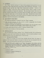
GENERAL
A.
The "Menu" software package
is
a
menu
driven
program which provides
real time
continuous video image processing using lookup table modification techniques.
provides limited non-real time single frame enhancement capability.
routines in
"Menu"
varies
provide
maximum
effectiveness in situations
also
Control of the
from manual (requiring operator input to make an
ment) to automatic or "hands-ofT operation.
It
adjust-
The processing routines were chosen
to
where the images' pixel values are limited
Typically this would include
to a relatively small region of the total gray scale range.
images of objects which have actual small variations
in
shading or those whose contrast
has been reduced by obscuration or dim lighting.
EQUIPMENT REQUIRED
B.
The following equipment
is
required to use the
"Menu" program:
IBM Personal Computer AT, XT, or PCl or 100% compatibles with Extended
Graphics Adaptor card and monitor.
•
Imaging Technology PCVISIONplus Frame Grabber card with standard cable.
older model PCVISION Frame Grabber will not work.)
•
(NOTE: The
SONY
Trinitron Model 1271Q).
•
Analog video monitor (such as
•
Video source (camera or video tape player).
SIMPLE SETUP
C.
The PCVISIONplus Frame Grabber User's Manual provides
required to place the
Frame Grabber
into operation.
Here
is
a
all
the information
much condensed
version
of that procedure with some helpful hints to ease the way.
1.
Getting the Board Ready
Figure 2-1 on page 2-2 of the Frame Grabber
cations on the board and Table 2-1 on page 2-3
factory.
tells
Manual shows
how
the jumper lo-
they are configured from the
There are three position functions to be concerned with:
Since an EGA card is needed to run "Menu" the memory base address must be
changed on the Frame Grabber board. Address D0000 is recommended since this
is the default value in the software.
To change to address D0000 simply insert a
jumper at location J 8. If other than D0000 is chosen it should be noted for entryeach time "Menu" is run.
•
1
Trademark of IBM.
2
Trademark of Imaging Technology
3
Trademark of
SONY
Inc.
•
•
a default register base address of 100. To change the FrameGrabber
board insert a jumper at location J 11. Again, if 100 is not used, the chosen value
will have to be entered each time "Menu" is run.
"Menu" has
If
is
an AT host is being used a jumper is required at location J20.
being used no jumper should be installed at J20.
Installing the
2.
If
an
XT
or
PC
Board
Pages 3-1 through 3-3 of the FrameGrabber Manual provide a detailed description for installing the board.
A summary
•
Turn
•
Remove
•
Place the board in any open slot where
•
Reinstall cover.
•
Plug in and turn on computer.
off
and unplug the computer and
is
as follows:
periphials.
the cover.
it fits
and
Cable Installation
3.
Page 3-5 of the Frame Grabber Manual shows
the
install screws.
bottom
how
to connect the cable. Here's
line:
•
Plug the rectangular female connector on the cable into the top connector
protruding from the board.
•
Connect the white labeled
•
Connect the green labeled
•
Do
BNC
connector to the video source output.
BNC connector to the
of the red, green, blue connections).
'line'
input (not the 'green' input
not connect the red- or blue-labeled cables.
Running the Diagnostics.
4.
Page 3-10 of the Frame Grabber Manual describes the procedure for running
the diagnostic software included with the
Frame Grabber. Since
tion has been changed as described above, the
command < configure >
entered followed by the register base address (100) and the
(D0000).
The diagnostics take
the factory configurawill
memory
several minutes to run so be patient.
As
have to be
base address
stated in the
manual, system memory or other devices mapped into the same memory space or
ter addresses will
D.
LETS TRY
This
is
cause some tests to
IT
regis-
fail.
OUT
an introduction to the "Menu" program.
It let's
you walk through some of
the features of the program; sort of a hands-on familiarization.
If
you
are not familiar
with some of the concepts described in this section, or with digital image processing in
general,
you should probably have a look
ment
an appendix.
as
Now turn
On
It
Primer which
at the
is
included in this docu-
explains the neccessary ideas in just a few pages.
VCR) and
on your source (camera or
video monitor to
let
them warm
up.
your computer go to the directory where you want to keep the program and copy
'menu.exe' there.
Load the Program
1.
To
>
ter
now
No < en-
word 'menu' followed by < enter >.
needed for any selection from here on out unless otherwise noted.
is
should
get started simply type the
be displayed on the computer monitor.
If
The menu
you are not using the memory
base address (D0000) and register base address (100) as described in paragraph
hit 'K' to
change setup and follow the instructions on your monitor.
Menu
selection 'E' provides continuous acquisition
Hit E' and you should see
real time video images.
you're using a tape
make
live
action from your camera or
you press the play button
sure
and display of the incoming
VCR
first).
Take a Snapshot
3.
Now let's
You
frame.
stored
above,
Live Action
2.
(if
C
now
freeze the action.
Hit
'F' for
snap. This acquires and displays a single
should see a stop action snapshot on your video monitor. The image
in
framegrabber
memory A,
the default
memory chosen when you
is
also
started
up.
Take Two Snapshots
4.
Now
The second snapshot
memory
7
is still
B.
there.
memory
hit 'D' for display
is
now
Try going back to
Note
that
we
B.
Take another snapshot with the
'F' key.
displayed on the monitor and stored in framegrabber
memory A
(the
are using the display
More on
keys to perform these operations.
C
key) to
memory
select
make
sure the
first
keys and not the select
memory
later
when we
snapshot
memory
start storing
images.
5.
All
Black
Let's erase
the
G' key
one of our snapshots. Display memory B (the 'D' key) and then
hit
memory B
to
for screenclear(O).
This clears the screen and framegrabber
black or intensity level zero.
6.
All
White
While
screen and
still
in
memory B
memory B
hit the 'H'
key for screenclear(255).
to white or intensity level 255.
intensitv levels while liahter shades
have higher intensitv
This erases the
Darker gray shades have lower
levels.
Put Your Snapshot
7.
in the
Saving an image to disk
bum. You should
A
still
A
in
director}' or
is
Type
a
name
disk.
(e.g. 'a:
is
safely
T
Open
Album
the
to
image was
file
mem
This selects
For our purposes we have selected the
Now
hit the
T key and you will be asked to
the image on the current disk
image') to store
give
it
in a different place.
Then
a label or simply type 'none' (note
it
The
disk drive selected should
tucked away in the "photo album"
really saved.
Then
name
The image should appear on
C
selected (the
make
the image
(i.e.
using 'A' or
'B'.
Now
hit
(followed by < enter >) to read the image from
the video monitor. If it does not, display the
memory
appear.
will
process real time video images using
let's
Hit the
ification techniques.
how your image
vertical represents
On
Try them!
blue line
is
effect
called analysis, but really
The graph you
('F')
and grab
try the invlut
on the image
unprocessed
live action.
live
Keys
'P'
see
it
table
just lets
you
on your computer monitor
pixel values
mod-
is
see
the
and the
computer monitor screen are the current options available
('G') options
(T) option and
work the same
see
the current lookup table and the green
have
You can
its
The horizontal coordinate represents input
the top of the
Now
-
some simple lookup
output values.
The snap
selection.
L' key
being changed.
is
current lookup table.
still
memory
select a
and the image
or 'D' key)
both frame memories as
First erase
Simple Processing
Now
we
memory A.
al-
See Your Snapshot
Type the image
key.
9.
The
If not, use the display
select
(e.g. 'image') to store
described in paragraph 5 or 6 above.
you
key to
required for each of these inputs).
Let's see if the
disk.
hit the 'A'
photo
in a
written to the disk).
8.
the
frame memory A.
comment. You may
for a
some noise and your snapshot
file is
on
to store
path and name
prompted
< enter >
that
in
Now
get one.
memory A
enter an image name.
you'll be
analogous to putting your snapshot
for data manipulations or storage.
image data
and
is
have an image
and snap routines to
memory
Photo Album
is
is
how
hit the 'L'
on the previous menu.
the lookup table changes (the
a reference linear lookup table
just like looking at the negatives
Now
as
for
line).
of a photograph, except that
key for linear lookup
table.
We
are back to
images.
(logarithmic) and 'A' (absolute value) also modify the lookup table.
experiment with these functions to see the
their corresponding
lookup table shape.
effect
on the
real time
image and
Histogram Equalization
10.
Now
for the
most powerful of our lookup
You now
for equalize.
are given
which portion of the image
probably use the default
will
On
rectangle.
'8'
two choices, default and
mode but
you
Now
hit
'Num
now
rectangle
let's try
will see the live
Most of
size
of the rectangle.
not interested,
it
If
would
Using the
update
and
first.
live
you have
'2', '4', '6',
move
and
the rectangle
and'9') are used to change the
on the area of
lessen the impact of the equalization routine
placed the rectangle where you
Now
'7',
Hit 'R' for
your image had a large white or black area in which you were
So you would frame the area of
terest.
'3',
you
images being displayed with a
Lock' on your keyboard.
The corner numbers (T,
the time
just for fun.
keys on the number pad (the ones with the arrows) you can
around on the screen.
Hit 'E'
This determines
rectangle.
be used to do the processing.
will
the video monitor
rectangle overlaid.
table modification routines.
w ant
T
it,
hit 'S' for stop.
The image
Hit the 'M' key.
After you have
interest with the rectangle.
Try manual
between manual or automatic update.
to choose
action continues using the
in-
will equalize, the
new lookup
table.
new lookup
table
is
plotted,
In this mode, as you notice the
contents of the image changing you can hit the 'U' key and equalization will occur again.
Let's
Now
parameters.
for time
will
go back
now and
hit 'D' for default
between updates
perform
a
new
and 'C
in seconds.
for
you
specify.
This
ations where the contents of the image are changing often and
to
remember
to update.
When you
have seen enough updates
is
9.
are
change
prompted
The computer
intended for
you don't want
situ-
to have
hit 'S' for stop.
Before and After
11.
Let's look at
some histograms and
the 'H' key for histogram.
Again, you
specify a portion of the image.
goes away
this
hit
see
w hats happening when we
r
may choose between
default or rectangle to
After the
When
time hit 'D' to display the linear lookup table histogram.
mation used to perform the equalization.
Now
'E'
The image on
hit 'E' to display the
enhanced and the "spread out" histogram
between 'D' and
you can
Hit
Now hit the 'L' key for computation
"COMPUTING HISTOGRAM" indicator
'M' for computation of modified histogram.
processed version.
equalize.
Hit 'D' for default.
of linear lookup table histogram.
away
You
continuous update.
Enter any number 2 through
equalization at the interval
C to
Hit
try the default rectangle parameters.
is
see graphically
how
This
is
the video monitor
modified histogram.
displayed.
the indicator goes
As you
the inforis
the un-
The video image
is
toggle back and forth
equalization lets us use the
full
range
of intensity levels and the corresponding enhancement of contrast on the image.
vinced?
Hit the
key and
'S'
Now
Hit the 'N' key.
Using the corner keys (T,
moving the top
move
else.
'3', '7',
bottom of the
or
'9') we'll
and
To shallow
curve.
you modify the
in the
computer. We'll talk about that
If
you were
are finished
to develop a "fais
a
way
to save
later.
'M' to perform another form of manual lookup table modification.
hit
We'll do this by drawing
Using the number pad with
lines.
pointer on the computer monitor by hitting the
one pixel
of these
Notice that
left.
When you
curve.
key
Draw Your Own Lookup Table
Now
in the
shown.
is
'9'
out the lookup table use the
T key to move the bottom to the
and the resulting lookup table
Lock' on.
change the slope of the lookup table by
lookup table which you think you might want to use again, there
13.
it
'Num
go again to the number pad with
to the live images changes as
hit 'S' to stop
it
we'll
the top to the right and the
enhancement
vorite"
something
Modifying the Lookup Table
12.
to
let's try
Con-
will
same
in the
it
same
'2'
direction as the
you want the
line to
where you want the
and your change
will
'8'
and
Lock' on
keys.
move
This will
the
move
of the arrows on the keys. The next key clockwise from each
in the direction
move
'2', '4', '6',
'Num
direction ten pixels
key only
begin
hit 'B' for
line to
end and
faster.)
begin
table.
The T' key moves the pointer
the pointer
is
at a location
Then move the pointer
end
line.
Now
hit 'D' to
You may draw
take effect on your image.
segments and build a whole new lookup
(e.g.
When
line.
hit 'E' for
.
To
where
to a location
draw the
line
other lines to connect
get rid of the clutter just hit
'S'
and
then reenter the routine by hitting 'M'.
Now
the
hit 'P' to
number pad keys
put a pointer on the
in the
same manner
puter monitor described above.
live
as
video image.
you
to find the intensity level of
table routine to change
to
draw
a really
all
an object
the modify routine.
Hit
'S'
the pointer on the com-
One
in the
possible use of this capability
image and use the draw lookup
pixels with that intensity to another level. Again, if
good all-purpose lookup
we'll describe later.
move
the pointer use
Notice on your computer monitor that the position of
the pointer and the intensity level are displayed.
would be
did to
To move
table,
to exit the video
you could save
it
you were
with a routine which
monitor pointer routine and
'S'
again to exit
some
routines and try
menu
go back to the main
Finally, let's
single
to see the
lookup table storage/selection
Type
frame (frozen) processing.
to exit the analysis
'S'
function.
Storing and Retrieving Your Favorite Lookup Tables
14.
Remember
Here's
or
how you can
that lookup table
save
mylut'), hit enter,
'a:
will
Hit the 'M' key. Type in a
for future use.
it
and the values are saved. To get
the lookup table values from disk.
your lookup table
you designed using the modify routine a while ago?
take
Again, type in the
hit the 'N'
name
key to read
followed by enter and
effect.
The framegrabber board has two
into frame
memory and one
as the image
have only used the output lookup
Hit the
ferent result.
analysis routine ('L')
as the last time
we
back
to the
equalized
,
main menu and
Now
modify both
we'll
Now exit the
You may now
and you
select
and
is
to this point
put
we
sets to achieve a dif-
Then go back
Everything
still
to the
looks the same
including the video image, but this time the
main menu. Hit the
back to normal,
Up
output to the monitor.
key to select the input lookup table.
'P'
(e.g. invlut, abslut, etc.)
get
is
and do a histogram equalization.
go back into analysis.
To
of lookup tables, one as the image
sets
table.
values went into the input lookup table.
age.
file
back
(e.g. 'mylut'
Piggyback Lookup Tables
15.
to get
it
name
computed
equalization and analysis routines
'O' key to select the output
lookup
table.
Then
use any of the lookup table modification routines
will get a
"piggybacked" lookup table effect on the im-
hit 'L' to linearize the
linearize the input
output lookup table.
lookup
table.
"Note that
Go
back to the
when you
use this
procedure, always put values derived by equalization into the input lookup table or the
on already modified
equalization will be based
16.
Zoom
Now
hit the 'R'
see the rectangle
we saw
key to
the rectangle with the
keys.
The
size
of
this
one
zoom
function.
'2', '4', '6',
and
'8'
you wish
to
Notice that some resolution
is
zoom
lost
in
on and
from the
Now
hit 'S'.
Move
Lock' on you can
the rectangle to the por-
The expanded image
original because
lens.
you can process the "zoomed" image using the
tines described below.
'Num
you can
one quarter of the screen, since we
opposed to changing the focal length of the camera
menu.
the video monitor
keys in the direction of the arrows on the
fixed at approximately
is
On
Using the number pad with
be expanding the image to four times the original.
tion of the image
as
start the
before.
move
will
data.
we
is
displayed.
are "zooming" digitally
Hit 'M' to get back to the
fixed
image processing rou-
Unzoom
17.
To
return to a normal image after using the
image processing
fixed
hit the 'R' key.
It is
zoom
essential that this be
"zoomed" image or the zoom parameters
finished with a
routine and performing any
done when you are
will interfere
with other rou-
tines.
Sharpen
18.
Snap an image by
Then
sharpen
hit 'S' to
hitting the 'F'
it.
If
key or by using the
you watch
closely
you can
zoom
routine (the 'R' key).
see the sharpening occurring
on the displayed image.
Low Pass
19.
Snap
or
This function
is
Filter
zoom
another image and then
T'
to call the
low pass
filter
routine.
designed to remove high frequency noise from a fixed image.
Again,
hit
looking closely you can see the change occurring.
An Edge
20.
One more
Edge
a Sobel
Detector
time, snap or
Filter.
Note the
zoom an
image.
This time hit the 'U' key to perform
interesting display of the image's edges
on the video
monitor.
Image Averaging
21.
Hit the
together.
(2
is
a
This
'V
key.
Then
number may be
good number
enter the
number of image frames you want
limited by the
to start with).
When
amount of
disk space
the average image
is
to average
you have
available
displayed you should
notice that objects which passed across the field of view during the operation have faded
away.
The more frames you average, the
averaging
less visible these objects will
become.
Image
very effective at eliminating transient noise, but requires a stable platform
is
for the source.
To
E.
exit the
program
hit the
"W
key.
QUICK REFERENCE LIST
This
list
presents the program's options in the order they appear with a brief de-
scription of their output.
A
1.
for select
mem A
Selects framegrabber
B
2.
for select
C
A
memory
D
4.
for display
memory B on
E
5.
disk.
memory B
for storing or reading
an image to/from
disk.
memory A
for acquisition of
image from camera and
dis-
for acquisition of
image from camera and
dis-
on the monitor.
mem B
Selects framegrabber
plays
an image to/from
mem A
for display
Selects framegrabber
plays
for storing or reading
mem B
Selects framegrabber
3.
A
memory
memory B
the monitor.
for grab
Continuously acquires image frames from source and displays on video monitor.
Uses framegrabber
F
6.
memory
designated by 'display
mem'
function.
for snap
Acquires a single frame from source and displays
framegrabber
G
7.
memory
designated by 'display
H
I
memory
to intensity level 0.
memory
to intensity level 255.
to store
image
Stores contents of selected
ing path if desired) and
10.
J to read
to
to disk.
Prompts input of filename
(includ-
image
of filename (including path
K
memory
comment.
Reads image from disk
11.
function.
for sclear(255)
Clears screen and
9.
on the video monitor. Uses
for sclear(O)
Clears screen and
8.
mem'
it
file
to selected
framegrabber memory.
Prompts input
if desired).
change setup
Allows change of software
memory
base address and register base address.
On
screen instructions and example inputs provided.
12.
L
for analysis
Displays lookup tables and histograms. Performs equalization and lookup table
modification routines.
a.
Options as follows:
m= modlut
Modifies lookup table by drawing
Move
lines.
Places pointer on video monitor.
pointer to desired start point and end point using
'Num
Lock' on and number pad
'2', '4',
keys
and '3'
and
'6',
for faster
and
'8'
down,
left,
movement down,
left,
for
(1)
b — beginline.
(2)
e= endline.
(3)
d= drawline.
(4)
p = pointer.
up,
Use keys T,
right respectively.
'7', '9',
up, and right respectively.
Marks beginning of line.
Marks end of line.
Draws
line
and enters new values into lookup
table.
Places pointer on video monitor. Gives pointer location
pixel intensity level of that location
move
and
on computer monitor.
Use same method to
pointer as for line drawing routine above.
(5)
b.
s= stop.
n = mod2
Exit lookup table modify routine.
lut
Changes slope of existing lookup
Lock' on use number pad keys
spectively.
Use 'T and
'9'
T
and
'3'
to
and implements
table
move bottom of
move top of curve
keys to
and
left
results.
curve
left
With 'Num
and
right re-
Hit
right respectively.
Y
to exit this routine.
c.
h
= histogram
Computes and
displays histograms for images processed with linear and
Snaps images before and
modified lookup tables.
and allows
after processing
for
com-
parison.
d= default. Selects
(approximately 90% of image).
(1)
tion
(2 j
r=
default portion of
image for histogram computa-
Displays rectangle superimposed on image on video
rectangle.
monitor. Change portion of image used for histogram computation by altering rectangle
size
and location. With 'Num Lock' on, use number pad keys
rectangle down,
decrease height.
left,
Use
right,
'7'
and up
and
'9'
respectively.
Use
T
and
'2', '4', '6',
'3'
and
'8'
to
move
keys to increase and
keys to increase and decrease width.
Hit
Y to
exit rec-
tangle routine.
(3)
LUT. Displays
(4)
modified
/= com
m— com
modhist.
message
d=dis
linhist.
e=dis modhist.
until done.
message
until done.
Displays histogram computed above using image
Unprocessed image shown on video monitor.
Displays histogram computed above using image
processed by modified lookup table. Processed image shown on video monitor.
(7 j
s=stop.
linear
Computes histogram of image processed by
"COMPUTING HISTOGRAM"
processed by linear lookup table.
(6 j
Computes histogram of image processed by
"COMPUTING HISTOGRAM"
LUT. Displays
(5)
linhist.
Exit histogram routine.
10
d.
e—
equalize
Performs histogram equalization with update on
(approximately
d= default.
90%
Selects default portion of
image to use for equalization
of image).
r=
(2)
rectangle.
Allows use of rectangle to specify portion of image to
be used as described in histogram rectangle routine above (paragraph
c=
(3)
specified intervals.
this
or automatically
Displays resulting lookup table after each update.
at specified intervals.
(1)
command
Selects automatic update of
continuous update.
Prompts
12. c. (2)).
Hit
for desired interval.
's'
lookup table
to exit equalization routine
at
from
mode.
m = manual update.
(4)
(a)
u = update—
(b)
c
Selects
lookup table update on command.
Performs new equalization and updates lookup
table.
= changeparam—
Returns
to
default/rectangle
portion
of
image options for changing parameters.
(c)
f= freezeframe—
(d)
g
(e)
s= stop—
= grab—
Acquires and displays a single frame (snap).
Continuous
acquisition
and
display
of
frames.
e.
1=
linlut
Sets
/.
p=
Sets
h.
lookup table to
linear values.
Results in unprocessed image.
i=invlut
Sets
g.
Exit equalization routine from this mode.
a
=
lookup table to inverse values. Produces a negative image.
loglut
lookup table to logarithmic values. Increases image brightness.
abslut
Inverses intensity levels greater than 127.
i.
Reduces image brightness.
g = grab
Continuous aquisition and display of image frames.
j.
f= freeze
Aquisition and display of a single frame (snap).
k.
s
=
stop
Exit analvsis routine.
11
image
13.
M to store lookup table
Stores contents of selected lookup table to disk.
(including path
14.
N
Prompts input of filename
if desired).
to read lookup table
Reads lookup table values from disk to lookup table they were stored from.
Prompts input of filename (including path
15.
O
if desired).
to select output lookup table
Selects the output
lookup table to perform modifications on and for display
When
the analysis routine.
used in conjunction with
input lookup table)
'P' (select
in
al-
lows for processing through two modified lookup tables.
16.
P
to select input lookup table
Selects the input
When
analysis routine.
for processing
17.
Q
lookup table
to
left,
"Num
right,
R
Lock" on use number pad keys
and up
respectively.
S
for
Hit
z'
to stop rectangle
T
'8'
filter.
May
be used on zoomed image.
U
for
filter
May
operation on a fixed image.
Reduces high frequency
be used on zoomed image.
edge detector
May
V
for
image average
of number of frames to average.
W
Displays detected
be used on zoomed image.
Averages specified number of image frames and displays
23.
rectangle
and fix/zoom image. Hit
Performs Sobel edge detector operation on a fixed image.
22.
move
for Ioav pass
noise. Blurs the image.
edges.
to
sharpen
Performs a low pass
21.
and
state.
Sharpens fixed image using a high pass
20.
'2', '4', '6',
unzoom
for
Returns image to normal
19.
Provides moveable rectangle to select area for
main menu.
'm' to return to
18.
tables.
zoom
Enlarges chosen area of image.
down,
in the
used in conjunction with 'O' (select output lookup table) allows
through two modified lookup
for
zoom. With
perform modifications on and for display
for
framegrabber
off
and exit program
Terminates program.
12
results.
Prompts input
APPENDIX
DIGITAL IMAGE PROCESSING PRIMER
A.
GENERAL
A.
This appendix provides the reader with some background on the basics of digital
image processing.
pixels
It
and how gray
makeup of
describes the
level
shading
is
a digital image, including the concept of
accomplished.
basic tool in the analysis of a digital image. Finally
is
It
it
also describes the histogram, a
introduces the lookup table, which
"Menu" program.
the primary image processing tool used in the
THE DIGITAL IMAGE
B.
Think about a black and white photograph. Suppose you were
it
which
512
=
Each square
262,144 tiny squares.
pixel to see
level 0.
If
The
512 squares across by 512 squares down.
is
what color
white
it is
it
If it
it is.
will
black
is
is
called a pixel.
will
it
up
It's
into pixels
pixel has
been assigned an intensity
the framegrabber
placed into frame
it is
somewhere
memory
Different
level 255.
and 255, with lower numbers
Once
for lighter grays.
intensity levels are then stored in order
divided into 512 x
look at an individual
be assigned the highest number, intensity
and higher numbers
and each
Now
is
on
be assigned the lowest number, intensity
shades of gray will be assigned intensity levels between
for darker grays
picture
to overlay a grid
the image has been broken
level,
in the
(either
A
it is
said to be digitized.
computer.
In the case of
or B) for processing and; or
passing on to the monitor.
C.
THE HISTOGRAM
Now let's look at our
level 0) are in
it.
Then
(intensity level 2),
we
are finished
we
digitized
we'll
how many
count the dark, dark grays (intensity
and so on,
will
image and count
all
the
way up
black pixels (intensity
level 1), the
to the whites (intensity level 255).
have analyzed the image with respect to gray
plot of this gray level content
is
dark grays
called a histogram.
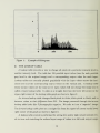
A
histogram
is
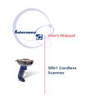
When
level content.
A
normally plotted as
a bar graph, with the intensity levels (0 to 255) plotted across the bottom, and the
number of pixels which have each
"Menu" program has
of an image.
intensity plotted as a vertical bar (see figure
a routine which allows
The histogram values
1).
The
you to compute and display the histogram
are also used in an important lookup table modifi-
cation technique, the histogram equalization.
13
Figure
D.
1.
Example
of
Histogram
THE LOOKUP TABLE
A lookup table provides a way
another intensity
level.
The
to
change
all
pixels of a particular intensity level to
table has 256 possible input values (one for each possible
gray level in the original image) and a corresponding output value for each input.
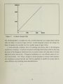
Lookup
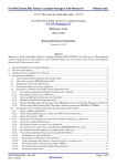
tables are normally plotted graphically with the input values across the hori-
zontal axis and the corresponding output values on the vertical axis.
whose output values
called a linear
upper
lookup
table.
right corner of the
An
same
It
as
it's
lookup table looks
input values will not change the image and
plots as a straight line
lookup table graph as shown
their difference
like a
from 255.
right corner of the
els to
from the lower
left
photographic negative.
graph as shown
lookup table stretch
is
We
is
corner to the
in figure 2.
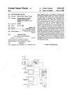
The image processed through
inverse lookup table plots as a straight line
A
lookup table
inverse lookup table changes black pixels to white, white pixels to black,
between values to
The
are the
A
refer to
it
from the upper
and
in
the inverse
as a "negative" image.
left
corner to the lower
in figure 3.
performed by setting low and/or high valued intensity
zero and stretching the reduced input range of values to a
14
full scale
lev-
output range.
Figure
The
2.
resulting
A
Linear Lookup Table
graph
table (see figure 4)
is
a straight line with a steeper slope
and the image
will
have overall enhanced contrast; the steeper the
slope, the greater the contrast, but for a smaller range
A
more powerful, nonlinear form of
equalization technique.
It
different
no
pixel counts
Histogram equalization
enhancement. The "Menu" program
many
is
the histogram
performs localized stretching of the lookup table by detecting
high pixel count areas across.
tion techniques
ofinput values.
stretching the lookup table
the areas of the histogram which have few or
trast
than our original linear lookup
is
is
and using them
a very efficient
to stretch
means of con-
based primarily on lookup table modifica-
and provides the user with the capability to modify the lookup table
ways including those described above.
15
in
OUTPUT
260
10B
Figure
3.
An
Inverse
Lookup Table
OUTPUT
280
100-
*
1
i
i
Figure
4.
A Lookup
I
200
100
Table Stretch
16
i
INPUT
INITIAL DISTRIBUTION LIST
No. Copies
1.
Defense Technical Information Center
2
Cameron
Station
22304-6145
Alexandria.
VA
2.
Library. Code 0142
Naval Postgraduate School
Monterey. CA 93943-5002
3.
Department Chairman. Code 62
Department of Electrical and Computer Engineering
Naval Postgraduate School
2
1
Monterey, California 93943
4.
Professor C.
W.
Therrien.
Code 62
3
Department of Electrical and Computer Engineering
Naval Postgraduate School
Monterey. California 93943
5.
Professor Roberto Cristi. Code 62
Department of Electrical and Computer Engineering
3
Naval Postgraduate School
Monterey. California 93943
6.
Professor
M. Fargues. Code 62
1
Department of Electrical and Computer Engineering
Naval Postgraduate School
Monterey. California 93943
7.
Professor Ralph Mippenstiel.
Department of Electrical and
Code 62
Computer Engineering
1
Naval Postgraduate School
Monterey, California 93943
8.
Professor Murali Tummala, Code 62
Department of Electrical and Computer Engineering
Naval Postgraduate School
1
Monterey. California 93943
9.
Mr. Richard Evans
NL'W'ES. Code 7021
Naval Undersea Weapons Engineering Station
Keyport, Washington 98345
17
2
10.
CDR
Hillier
NUWES, Code
80
Naval Undersea Weapons Engineering Station
Keyport. Washington 9S345
11.
Mr. Alan
L.
Lindstrom
NUWES, Code
70
Naval Undersea Weapons Engineering Station
Keyport, Washington 98345
12.
Professor O. B. Wilson
Department of Physics
Naval Postgraduate School
Monterey, California 93943
13.
MAJ William J. Partridge
Student Detachment
U.S. Army Command and General Staff College
Fort Leavenworth, Kansas 66027
14.
Research Administration
CODE:
012
Naval Postgraduate School
Monterey, CA
93943
DUDLEY KNOX LIBRARY
3 2768 00347355 4