1
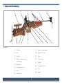
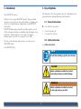
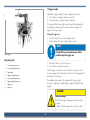
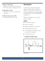
User Manual
1827 F ANSCHÜTZ Biathlon Series Models
Issue 06/2011
Contents
1 Components / Terminology................................. 4
10Safety catch........................................................... 14
2 Introduction............................................................. 5
10.1 Engaging the safety catch......................................14
10.2 Releasing the safety catch......................................14
3 Key to Symbols....................................................... 5
11Filling the magazine.......................................... 15
3.1
3.2
General instructions................................................5
Safety instructions...................................................5
12Spare magazine retainer / cartridge retainer............................................... 16
4 General handling of firearms.......................... 6
4.1
4.2
4.3
4.4
4.5
4.6
12.1 Spare magazine retainer.......................................16
12.2 Spare cartridge holder..........................................17
Important basics.....................................................6
Shooting................................................................7
Maintenance..........................................................8
Transport................................................................8
Storage..................................................................8
Hearing and eye protection.....................................8
13Removing / inserting the bolt.......................... 17
14Dismantling / assembling the bolt................ 19
15Cheek piece........................................................... 20
5 Legalities.................................................................. 8
15.1 Removing the cheek piece.....................................20
15.2 Adjusting the cheek piece......................................20
6 Intended use........................................................... 9
16Buttplate................................................................. 21
7 Liability..................................................................... 9
16.1 Removing the buttplate..........................................21
16.2 Adjusting the buttplate..........................................21
8 Assembly and attaching the barrelled action........................................... 10
17Trigger..................................................................... 21
9 Loading / unloading. .......................................... 11
18Dry firing device.................................................. 26
9.1
9.2
Loading...............................................................11
Unloading............................................................12
2
19Maintenance / cleaning..................................... 27
19.1
19.2
19.3
19.4
19.5
General...............................................................27
Cleaning the barrel...............................................28
Maintenance intervals...........................................29
Trigger maintenance.............................................29
Maintenance of the optical sights...........................29
20Optical sights........................................................ 30
20.1 Mounting.............................................................30
20.2 Elevation and windage adjustment.........................30
20.3 Zero adjustment....................................................30
21Troubleshooting................................................... 30
22Technical data...................................................... 30
23Disposal.................................................................. 31
24Miscellaneous....................................................... 31
25Shooting Performance. ..................................... 32
26Guarantee. ............................................................ 32
3
1 Components/Terminology
[1]
[2]
[3]
[4]
[5]
[6]
[7]
[16]
[15]
[14]
[13]
[12]
[11]
[10]
Fig.1 Overview
[1]
Cheek piece
[9]
Magazine (in magazine guide)
[2]
Bolt
[10]
Magazine release lever
[3]
Breech case
[11]
Trigger
[4]
Magazines in magazine retainer (spare magazines)
[12]
Forend raiser block
[5]
Barrelled action
[13]
Bolt handle
[6]
Front sight with snow cover
[14]
Rear sight with snow cover
[7]
Muzzle
[15]
Stock
[8]
Cartridge holder
[16]
Buttplate
4
[9]
[8]
2 Introduction
3 Key to Symbols
Dear ANSCHÜTZ Customer,
In this handbook, the following symbols are used to distinguish between
general information and particularly important information:
Thank you for choosing an ANSCHÜTZ product. Many spectacular
sporting successes have been achieved by marksmen, olympians and
shooters in world and European championships using ANSCHÜTZ
sporting rifles.
ANSCHÜTZ hunting and sporting rifles are highly reputed as a result
of their well-engineered design, workmanship and outstanding shooting
performance. Quality and precision are a part of our tradition, and have grown as a result of our experience since 1856.
3.1 General instructions
XX is the symbol for an instruction
99 shows the desired result
yy
is the symbol for a list item
3.2 Safety instructions
We wish you much pleasure and sporting success with your new ANSCHÜTZ product.
$$ identifies a safety instruction
Your ANSCHÜTZ team
Note!
An instruction indicating a specific course of action.
Caution!
Indicates a hazardous situation that can lead .
to minor physical injury or material damage.
Warning!
Indicates a hazardous situation that can lead .
to serious physical injury or death.
5
4 General handling of firearms
$$ A firearm must only ever be used for its designated purpose.
Firearms are dangerous objects requiring the utmost care in their storage and use. The following safety and warning instructions must be observed without exception!
$$ Firearms owners are responsible for ensuring that their firearm is at no time, $
and especially when absent, within reach of or accessible to children or other $
unauthorised persons.
$$ Firearms must not be handed over to unauthorised persons.
Note!
$$ Only original ANSCHÜTZ magazines may be used.
The firearms legislation of the relevant country .
must be respected and complied with.
$$ The specified capacity of the magazines must not be exceeded.
$$ Modifications to the rifle or the use of non-genuine ANSCHÜTZ magazines $
and accessories can lead to malfunctions.
$$ Serious or life-threatening injuries and damage can be caused by the use of incorrect $
ammunition, by contamination in the barrel or by incorrect cartridge components.
4.1 Important basics
$$ Weapons modified in a way that could affect safety must not be used. If a fault or $
malfunction is detected, the weapon must be unloaded and taken to an authorised $
gunsmith for repair.
Note!
The use of firearms while under the influence of
drugs, alcohol or medication is not permitted.
Vision, dexterity and judgement can all be adversely
affected.
A good physical and mental constitution is a .
prerequisite for using a firearm.
$$ In the event of external effects (e.g. corrosion, being dropped, etc.), the weapon must be
checked by an authorised gunsmith.
$$ A weapon must always be treated with the utmost care and be protected from accidental
damage.
6
4.2 Shooting
$$ Any firearm must be treated as if it were loaded.
$$ Never pick up a firearm by the trigger.
Warning!
$$ Shooting galleries must be adequately ventilated.
Danger to life and causing material damage!
$$ Any bullet trap in the shooting gallery must be completely safe and visible.
Aiming the rifle at people and objects.
hh When the rifle is not in use, keep the muzzle pointing in a safe direction.
hh The muzzle of a firearm must never be held in
a direction where it can can cause damage or
endanger life.
$$ No persons may stand in the vicinity of the target during a shoot.
$$ Firearms should not be used when visibility is poor.
$$ Do not shoot into the air, at hard or smooth surfaces, at water or at targets on the horizon.
$$ Do not shoot at targets if the shot could ricochet or be deflected in a dangerous manner.
$$ To prevent accidents or damage to your rifle, never discharge a shot with the muzzle held
under water or up against materials or objects.
$$ Only shoot using the calibre specified on the barrel of the rifle.
$$ Only new, clean, factory-charged ammunition of the calibre permitted for the rifle $
may be used.
$$ The ammunition must conform to the specifications of the C.I.P.
Warning!
$$ Only ever load the rifle immediately before use.
Malfunction when shooting!
$$ Use only genuine ANSCHÜTZ magazines.
Shot not discharged after trigger pulled.
hh Do not look down into the muzzle.
hh Keep the muzzle of the firearm pointing in a safe direction.
hh Unload the firearm.
hh Remove residues from the barrel.
7
4.6 Hearing and eye protection
$$ The specified capacity of the magazines must not be exceeded.
$$ Life-threatening injuries and material damage can be caused by the use of incorrect $
ammunition, contamination in the barrel or incorrect cartridge components.
Note!
$$ Only genuine ANSCHÜTZ parts may be used.
For your own safety, approved hearing and eye .
protection should be used when shooting!
Shooting without safety equipment can result in .
damage to your hearing and sight.
4.3 Maintenance
$$ Ensure that the rifle is unloaded before and after use, or during maintenance $
and cleaning.
4.4 Transport
5 Legalities
$$ Firearms may only be transported in an unloaded condition and in locked containers.
$$ Only transport firearms in a clean, dry condition.
Note!
$$ Always place the rifle in the transport case with the sight facing upwards $
(towards the handle). This protects the rear sight from impacts and also protects $
the rear sight setting screws as a result.
The applicable firearms legislation, regulations and
provisions for the relevant country, and also the
safety rules of the hunting and sporting organisations must be observed.
4.5 Storage
$$ Firearms that are not in use must be kept in a secure place under lock and key.
$$ Firearms must always be stored in an unloaded and uncocked condition.
$$ Ammunition must be kept in a separate place under lock and key.
8
6 Intended use
7 Liability
The 1827 Fortner small-bore match rifle is a biathlon rifle. It must only
be used on shooting ranges (for sporting disciplines) and may only be
used by persons who hold the appropriate firearms certificate.
ANSCHÜTZ will accept no liability or claims for compensation
for damage of any kind arising from:
yy
yy
yy
yy
yy
yy
yy
yy
Its use is subject exclusively to the "General Technical Regulations" for all
shooting sport disciplines of the INTERNATIONAL SHOOTING SPORT
FEDERATION (ISSF), Bavariaring 21, 80336 Munich, Germany, or the
regulations of the INTERNATIONAL BIATHLON UNION, Peregrinstrasse
14, A-5020 Salzburg, Austria, E-mail: [email protected]).
failure to comply with the instructions in this user's handbook,
improper treatment or repair,
use of non-genuine ANSCHÜTZ parts,
incorrect handling or care,
negligence,
removal of the sealing lacquer,
unauthorised tampering or
transport damage.
Note!
A firearm must only ever be used for its designated
purpose.
Caution!
Modifications to or tampering with the rifle or its
parts are forbidden and may possibly infringe the
guarantee conditions..
Alterations of this kind can have an adverse effect on
the safe use of the product and lead to accidents that
endanger life and limb. In such cases the guarantee
is automatically void.
$$ The rifle must be examined for any changes before use on each occasion.
9
8 Assembly and attaching the barrelled action
XX Screw in the two bedding screws [a] and tighten them alternately
and evenly in stages.
Note!
[3]
The stock and the barrelled action are packed .
separately for safety reasons and will have to .
be assembled.
[5]
[15]
XX Wipe off any excess oil from the surface of the barrelled action.
XX Remove the magazine [9] and the two bedding screws [a].
XX Lay the barrelled action [5] in the milled-out channel in the stock
[15] (see Fig. 2).
[a]
[a]
Fig.2 Attaching the barrelled action
Note!
Note!
The transverse slot on the underside of the receiver
[3] must be pushed on to the iron abutment inserted
transversely in the stock [15].
The receiver [3] must not rest on the abutment.
For correct tightening of the action screws [a], ANSCHÜTZ recommends the use of the Modell 4405
torque screwdriver (Item No.: 001176), which must
be set to 5 Nm..
A palpable and audible clicking indicates that the .
set value has been reached.
Note!
Settling of the stock wood can occur after the initial
assembly of the barrelled action [5]. ANSCHÜTZ
therefore recommends loosening the action screws
[a] after a time and tightening them again in .
accordance with Chapter 8.
$$ The attachment of the barrelled action must be checked each time before shooting to
ensure that it is secure.
10
9 Loading / unloading
XX Push the full magazine [9] into the magazine guide until the magazine release lever [10] engages audibly.
99 The rifle is now loaded.
9.1 Loading
XX Close the breech [2] (push in the direction of the arrow to the end stop).
$$ Only ever load the rifle immediately before use.
Note!
Before the rifle is used for the first time, the breech
and the inside of the barrel must be de-oiled with .
a lint-free cloth.
[2]
XX Fill the magazine [9] (see Chapter 11).
XX Open the breech [2] (pull back in the direction of the arrow to the end stop).
Note!
The firing pin is cocked by opening the breech.
Fig.4 Closing the breech
Note!
Closing the breech causes a cartridge to be fed .
from the magazine to the barrel and the trigger .
to be cocked.
[2]
Fig.3 Opening the breech
11
9.2 Unloading
Warning!
XX Open the breech [2] (pull back in the direction of the arrow to the end stop).
Danger to life!
Unintentional discharge as a result of a loaded, unsecured rifle.
hh Keep the muzzle of the firearm pointing in a safe direction.
hh Engage the safety catch after loading the rifle.
[2]
99 The rifle is fully loaded.
XX Engage the safety catch (see Chapter 10).
Warning!
Danger to life!
Fig.5 Opening the breech
Unintentional discharge as a result of inattentiveness
while engaging the safety catch or as a result of possible malfunctions after securing.
hh Even when the safety catch is engaged, the muzzle
of a firearm must never be pointed in a direction
where it can can cause damage or endanger life.
Note!
Any cartridge that is still in the chamber will be
ejected.
99 The rifle is fully loaded and the safety catch is engaged.
12
XX Close the breech [2] (push in the direction of the arrow to the end stop).
XX Push the magazine release lever [10] forwards (in the direction of
the arrow).
[2]
[10]
Fig.6 Unlocking the magazine
Fig.7 Closing the breech
99 The magazine [9] is unlocked and can be taken out.
XX Pull the trigger.
XX Withdraw the magazine [9] from the magazine recess by hand.
99 The rifle is unloaded and uncocked.
Caution!
Physical damage!
After it is unlocked, the magazine can fall out of the magazine on its own.
hh Place a hand under the magazine when unlocking it.
13
10Engaging / releasing the safety catch
Note!
[x]
The safety catch can only be engaged/released
when the rifle is cocked, i.e when the breech is open
(firing pin cocked) or after the loading procedure/
breech closed (firing pin and trigger cocked). .
The general "Engage/Release" procedure is .
described as follows.
Fig.10 Safety catch "Safe"
10.1 Engaging the safety catch
99 The rifle is cocked and the safety catch is engaged.
XX Open the breech [2].
XX Slide the safety catch [x] to the rear (in the direction of the arrow)
("S" is visible).
10.2 Releasing the safety catch
XX Close the breech [2] (push in the direction of the arrow to the end stop).
Note!
The safety catch must engage exactly and audibly
and must not sit between the end stops.
Note!
The safety catch must engage exactly and audibly
and must not sit between the end stops.
14
11Filling the magazine
XX Push the magazine release lever [10] forwards (in the direction of
the arrow).
[2]
Caution!
Material damage!
After it is unlocked, the magazine can fall out of the magazine on its own.
hh Place a hand under the magazine when unlocking it.
Fig.8 Closing the breech
XX Take the magazine [9] out of the magazine guide (in the direction
of the arrow).
XX Slide the safety catch [x] forwards (in the direction of the arrow) ("F" is visible).
[x]
[10]
Fig.11 Removing the magazine
Fig.9 Safety catch "Ready to Fire"
99 The rifle is cocked and the safety catch is released.
15
[9]
12Spare magazine retainer/cartridge retainer
XX Push the cartridge, base first between cut-outs on the sides, into the magazine [9].
12.1 Spare magazine retainer
Warning!
Danger to life!
The ANSCHÜTZ 1827 Fortner can accommodate up to 4 spare magazines in the spare magazine retainer [4].
XX To fill or empty the spare magazine retainer [4], simply push the
magazines [b] into the recesses up to the end stop or pull them out
(see arrows).
Incorrect calibre in the magazine.
hh Only use the calibre specified on the barrel of the rifle.
[b]
[4]
Fig.13 Spare magazine retainer
Fig.12 Magazine filled
XX The gripping force of the spare magazine retainer can be adjusted
by turning the magazine retainer screws [c].
$$ Only genuine ANSCHÜTZ magazines may be used.
$$ The specified capacity of the magazines must not be exceeded.
$$ Only cartridges of the calibre specified on the barrel of the rifle may be used.
$$ Only new, clean, factory-charged ammunition of the calibre permitted for the rifle $
may be used.
$$ The ammunition must conform to the specifications of the C.I.P.
XX Push the full magazine [9] into the magazine guide until the magazine release lever [10] engages audibly.
[c]
Fig.14 Adjusting the magazine gripping force
16
13Removing/inserting the bolt
12.2 Spare cartridge holder
XX Remove the cheek piece (see Chapter 15).
The ANSCHÜTZ 1827 Fortner can hold up to 6 spare cartridges in the
spare cartridge holder [8].
XX To fill the spare cartridge holder [8], push the cartridges head first
into the individual chambers.
XX Pull the breech [2] back (in the direction of the arrow, to the end stop).
[2]
[8]
Fig.16 Opening the breech
XX Pull the thumb rest [d] back (in the direction of the arrow) a little
and turn it clockwise until the notch in the thumb rest [d] is aligned
with the notch in the breech wedge [e].
Fig.15 Spare cartridge holder
[d]
Fig.17 Removing the bolt
17
[e]
XX Extract the breech wedge [e] (in the direction of the arrow).
XX Extract the bolt [2] (in the direction of the arrow).
[e]
[2]
Fig.18 Exracting the breech wedge
Fig.20 Extracting the bolt
XX Unscrew the end cap [f] in an anticlockwise direction.
XX The installation of the bolt [2] is carried out in reverse order.
XX Pull the bolt handle [g] back (in the direction of the arrow) and hold it under tension.
[f]
[g]
Fig.19 Unscrewing the end cap
18
14Dismantling / assembling the bolt
Note!
Dismantling of the bolt action should only be carried
out by an authorised specialist.
XX Remove the bolt (see Chapter 13).
(See Fig. 21 for the following designations)
XX Unscrew the connecting nut [5] until the front and rear sections can be separated.
XX Remove the spring support [6] and the firing pin spring [7].
Fig.21 Dismantled bolt
XX Press the bolt with locking pin [11] out in an upwards direction.
To reassemble, carry out these steps in reverse.
The following must be observed when doing this:
XX When screwing in the thumb rest [22] (approx. 4 turns), take care
that the nut plate [20] is sitting at right angles to the set screw.
XX Pull the cocking handle [15] to the end stop.
XX Pull the bolt clamping sleeve [19] out of the locking receiver (a perceptible resistance must be overcome to do this).
XX Before pushing the locking receiver and the bolt clamping sleeve
[19] together, fit the locking balls [12] into the locking receiver
from the inside (a little grease prevents the locking balls [12] from
falling out).
XX Press out the locking balls [12] to the inside.
XX Press the plunger [17] out of the bolt clamping sleeve [19].
XX Press the driving pin [13] upwards out of the bolt clamping sleeve [19].
XX When assembling the parts of the bolt, attach the connecting nut
[5] to the locking receiver with the teeth pointing away from the
direction of shooting and screw it together with the bolt body.
XX Withdraw the firing pin [18] to the rear.
XX Unscrew the thumb rest [22].
$$ When screwing the front and rear parts together, the two parts of the bolt must not be
rotated with respect to one another.
XX Extract the nut plate [20] and compression spring [21] for the thumb rest [22] to the side.
XX The connecting nut [5] has two opposite hand threads, both of which engage at the same time.
XX Tighten the connecting nut [5] by hand until the bolt body cannot be turned any more.
19
15Cheek piece
XX The point of the firing pin [18] must project from the action face of the bolt body.
XX Install the bolt (see Chapter 13).
15.1 Removing the cheek piece
XX Unfasten the clamping screw [x].
XX Remove the cheek piece [1] from the holder.
XX Fit in reverse order.
15.2 Adjusting the cheek piece
The cheek piece can be tilted to various positions. The knurled screws
[y] and the fixing screws [z] must be released to set to the various positions.
XX Release the clamping screw [x].
XX Release the appropriate adjusting screw for the desired tilt position.
XX Tilt the cheek piece [1] and retighten the corresponding adjustment
screw hand tight.
XX Retighten the clamping screw [x] hand tight.
[z]
[1]
[y]
[x]
Fig.22 Removing the cheek piece
20
16Buttplate
17Trigger
Warning!
16.1 Removing the buttplate
Danger to life!
XX Release the clamping screw [x].
Danger to life from loaded firearm.
hh Make sure that the rifle is unloaded when carrying
out alignment and adjustment procedures.
XX Remove the buttplate [16] from the holder.
XX Fit in reverse order.
16.2 Adjusting the buttplate
Caution!
XX Release clamping screws [x] and [z].
Material damage!
XX Turn the knurled screws [y] until the desired tilt and length are
achieved.
Damage to the trigger caused by the breech not being
open when the trigger is changed.
hh Open the breech when changing the trigger.
XX Move the buttplate [16] up or down until the desired height is set.
XX Retighten the clamping screws [x] and [z] hand tight.
$$ If just clamping screw [z] is released, only the height of the butt plate [16] will be able $
to be adjusted.
[16]
[y]
[z]
[y]
[x]
Fig.23 Buttplate
21
1 Trigger weight
[8]
Adjusting the trigger weight by means of adjusting screw [6]:
yy turn clockwise = trigger weight is increased (+)
yy turn anticlockwise = trigger weight is reduced (–)
The trigger and first stage weights are mechanically interdependent.
Any adjustment always results in a small concurrent change in the trigger or first stage weight.
[7]
Moving the trigger cam
yy lowest setting of the cam = least trigger weight
yy highest setting of the cam = highest trigger weight
[6]
[1] [2]
[3]
[4] [5]
Note!
A 2 mm Allen key and maybe tweezers will be
needed to adjust the trigger cam.
Fig.24 Trigger
Key (to Fig. 24)
1
First stage adjusting screw
2
Second stage adjusting screw
3
Trigger blade
4
Trigger stop adjusting screw
5
First stage pull adjusting screw
6
Trigger weight adjusting screw
7
Trigger cam
8
Firing pin
yy
yy
turn anticlockwise = loosen fixing screw
turn clockwise = tighten fixing screw
After the trigger cam has been moved it will be necessary to check the sear engagement (according to the subsection "Sear engagement")
and readjust it if necessary.
Fine adjustments are made to the trigger and first stage weights by means of adjusting screws [6] (trigger weight) and [5] (first stage
weight).
Caution!
Material damage!
Risk of fracturing the clamping screw with too high a torque.
hh Ensure that the trigger cam is correctly seated.
22
2 First stage weight (only with two-stage triggers)
Setting the optimum sear engagement:
Adjusting the first stage weight by means of adjusting screw [5]:
yy turn clockwise = first stage weight is increased (+)
yy turn anticlockwise = first stage weight is reduced (–)
$$ The rifle must be unloaded.
XX Cock the rifle and release the trigger (check whether the trigger
releases as desired).
The trigger and first stage weights are mechanically interdependent.
Any adjustment always results in a small concurrent change in the trigger or first stage weight.
If the sear engagement is too long:
There is a short travel from the second stage to the release of the trigger
(so-called "pull" or "tug").
XX After cocking and releasing the trigger, turn adjusting screw [2]
clockwise in steps (approx. 1/8 turn each time).
3 Sear engagement
The sear engagement denotes the travel from the second stage to the
release of the trigger.
XX Repeat the procedure until the second stage is no longer perceptible.
Warning!
XX Then turn back 1/5 turn anticlockwise.
Danger to life!
99 The optimum sear engagement is now set.
Unintentional discharge as a result of too short a sear
engagement and/or too low a trigger weight.
hh Do not set the sear engagement too short.
hh Do not set the trigger weight too low.
hh Do not subject loaded and unsecured rifles to impact and do not use force to close the breech.
If the sear engagement is too short:
There is no longer any second stage. The trigger releases indefinably
without a second stage.
XX After cocking, turn the adjusting screw [2] at least 1/4 turn
anticlockwise, release the trigger and check whether there is a second stage.
XX If not, repeat the procedure until there is a perceptible second
stage.
XX As soon as there is a perceptible second stage, proceed according
to the subsection "If the sear engagement is too long" to achieve
the optimum sear engagement.
Adjusting the sear engagement on a two-stage trigger by means of adjusting screw [2]:
yy turn clockwise = sear engagement is shortened
yy turn anticlockwise = sear engagement is lengthened
To set the sear engagement with a single-stage trigger using adjusting
screw [2], see Point 7.
23
4 First stage travel (only with two-stage triggers)
5 Trigger stop
First stage travel denotes the travel of the trigger blade from the zero
position to the second stage.
The trigger stop denotes the travel from the second stage to the end
stop for the trigger blade.
Setting the first stage travel by means of adjusting screw [1]:
yy turn clockwise = first stage travel is shortened
yy turn anticlockwise = first stage travel is lengthened
Setting the trigger stop by means of the trigger stop adjusting screw [4]:
yy turn clockwise = trigger stop is shortened
yy turn anticlockwise = trigger stop is lengthened
Warning!
Caution!
Danger to life!
Malfunction!
The first stage travel adjusting screw is set beyond the
second stage function.
hh Never turn the first stage travel adjusting screw
beyond the second stage function.
hh Never remove the first stage travel completely in
order to convert the two-stage trigger to a single
stage trigger.
Trigger stop adjusting screw has been turned beyond
the actuation point (trigger does not actuate).
hh Do not turn the trigger stop adjusting screw in beyond the actuation point.
6 Moving the trigger blade
Release clamping screw [3]. The trigger blade can both be moved
along the guide and also pivoted to the side.
24
8 Converting a single stage trigger to a two-stage trigger
yy Turn the trigger stop adjusting screw [4] approx. 2 1/2 turns
anticlockwise (set the max. trigger stop longer).
yy Release the safety catch and cock the rifle.
yy Turn adjusting screw [2] clockwise by approx. 2 1/2 turns.
99 The second stage is now perceptible.
7 Converting a two-stage trigger to a single stage trigger
Adjustments:
yy Turn the screw for the first stage travel [1] anticlockwise until the
maximum first stage length has been set.
yy Cock
yy Turn adjusting screw [2] (second stage) antickockwise until the trigger releases.
yy From this setting, turn adjusting screw [2] approx. 1/4 turn
clockwise.
99 The trigger is now adjusted for single stage; there is no longer any first stage travel.
$$ To set the optimum sear engagement, the procedure in Chapter 3 ("Setting the optimum
sear engagement") must be followed.
XX If required, the trigger characteristics can be set to the desired values as follows: first stage travel per Point 4, trigger stop per
Point 5, trigger weight per Point 1 and first stage weight per Point 2.
Warning!
Danger to life from automatic firing!
9 Trigger malfunctions caused by misadjustment
Automatically firing shots and malfunctions caused
by minimally set trigger weight and too short a sear
engagement.
hh Do not set the trigger weight too low.
hh Do not set the sear engagement too short.
Proceed as follows in the event of malfunctions caused by a misadjusted trigger:
XX The trigger function must be checked after every change.
XX When the malfunction has been rectified, check the desired trigger
characteristic and adjust it again if necessary.
The trigger catches the firing pin but does not fire when pulled:
yy Check whether the safety catch is engaged.
yy Check that the trigger cam [7] is present and screwed on correctly.
yy The trigger stop adjusting screw [4] is screwed in a few turns too
far (turn screw [4] anticlockwise by a few turns until the firing pin
[8] releases once more when the trigger is pulled).
25
18Dry firing device
The trigger does not catch the firing pin:
yy Adjustiing screw [1] (first stage) is screwed in several turns too far.
yy Check that the tension spring is not damaged and is fitted correctly.
The length of the firing pin is factory-adjusted to ensure that the cartridge detonates reliably. Long periods of dry firing without a cartridge or a case in the chamber can cause damage to the firing pin or the rim of the chamber. For this reason, either a spent cartridge
case (replace approx. every 5 shots) or a damping disc (1927F-40)
should always be used.
The single stage trigger is set too tight:
yy Turn adjusting screw [2] clockwise in 1/4 turn steps until the firing
pin [8] is caught.
The catch link return spring is too weak or is defective:
yy The trigger must be returned to the factory for repair.
With this device, match training can be carried out at any time without the use of ammunition.
Installation
XX Remove the bolt [2] (see Chapter 13).
XX Unscrew the connecting nut [c].
XX Withdraw the bolt body [d] from the rear part of the bolt.
XX Fit the damping disc [b] on the firing pin [a].
XX Screw the bolt body [d] and the rear part of the bolt together
evenly by means of the connecting nut [c].
XX Cock the bolt [2] and commence use.
$$ The damping disc must be removed again before a competition.
[b]
[2]
[a]
Fig.25 Dry firing device
26
[c]
[d]
19Maintenance/cleaning
Note!
After each use of the rifle, apply a thin film of oil to
the steel parts and thoroughly clean the barrel.
When the rifle is transported from cold to warm
rooms, condensation can form on the metal parts
and inside the barrel. If this condensation is not
quickly dried off, it can possibly lead to surface rust.
19.1 General
Warning!
Danger to life!
Danger to life from loaded firearm.
hh Ensure that the rifle is unloaded before use or during maintenance and cleaning work.
Note!
The rifle case / soft case should be cleaned regularly
and any dust and fluff removed.
Caution!
Rifle cases and soft cases should have a smooth,
dust-repellent lining.
Injury and material damage!
Danger of injury or material damage as a result of not removing the oil from the barrel and chamber.
hh Each time before shooting, any oil or foreign objects
must be removed from the barrel and chamber.
When not in use, the rifle case / soft case should
always be left open to allow moisture to escape. .
Enclosing a desiccant can reduce the moisture .
content.
Note!
Note!
To reduce the risk of breaking the stock during .
transport, ANSCHÜTZ recommends separating the
barrelled action from the stock, especially during .
air travel.
The rifle should be protected from dust, sand, .
moisture, heat and damaging influences.
27
19.2 Cleaning the barrel
Caution!
If the barrel is only slightly dirty, use a plastic brush to clean it.
XX Lightly oil the plastic brush and push it through the barrel from the cartridge chamber end with a suitable cleaning rod.
Always look out for any changes or damage that
may occur to the rifle.
In the event of a change or damage, the rifle must
immediately be taken to an authorised gunsmith or
sent to ANSCHÜTZ for inspection.
Fig.26 Plastic brush
If the barrel is very dirty, use a bronze brush together with a suitable
barrel cleaner.
Note!
Pay attention to the user instructions for the cleaner!
Fig.27 Bronze brush
XX Pull a woollen swab through the barrel several times to dry it.
Note!
It is essential to re-oil the barrel after using ammonia-containing cleaning agents, to avoid the risk of
corrosion.
28
19.3 Maintenance intervals
19.4 Trigger maintenance
yy
Lubricate the pivot bearing once a year with a thin, low-temperature oil.
yy Dab a small quantity of oil between the bearing parts with a needle.
yy To avoid gumming, adhesion or soiling of the trigger parts, never wash out the inner parts of the trigger with a spray or oil.
$$ No dirt, solvent residues, grease or unsuitable oils must get into the trigger assembly $
during maintenance of the rifle. ANSCHÜTZ recommends cleaning the rifle on its side $
or with the stock pointing upwards, which will prevent any adverse effects on the $
trigger assembly.
Note!
Pay attention to the instructions supplied with the
cleaner.
Before shooting
yy Carefully remove any oil from the rifle.
$$ The de-oiling of the rifle should be carried out at room temperature, as too many residues
can be left in the barrel if it is very cold.
After shooting
yy Pass a dry brush through the barrel (to remove powder residues).
yy Do not bring the rifle into warm rooms with the bolt locked and the snow cover closed (condensation).
19.5 Maintenance of the optical sights
Note!
The ANSCHÜTZ rear sight is a precision unit and
consequently requires the utmost care when .
handling..
Intensive care and maintenance guarantee perfect
function.
After the competition
yy Allow the rifle to warm up to room temperature with the breech and the snow cover opened.
yy Carefully remove condensate from the outside parts.
yy Dismantle the bolt action (see Chapter 14) and likewise remove the condensate from the individual parts.
yy Oil the rifle (including the stock) with a suitable gun oil.
yy Clean the barrel with a plastic brush and gun oil.
The rear sight must be protected from dust and dirt.
Spindles must not be oiled or greased.
If very dirty
yy Clean the barrel with a bronze brush and a suitable barrel cleaner.
yy Wipe the rifle (including the stock) with an oily rag.
Yearly
yy Take the rifle to a dealer/gunsmith for inspection.
29
20Optical sights
21Troubleshooting
Note!
Warning!
Operating and maintenance instructions can be found
in the individual manufacturer's documentation.
In the event of malfunctions (e.g. shots not discharged, etc.) the rifle must be unloaded, secured and
taken without delay to a specialist dealer/gunsmith
or sent to ANSCHÜTZ.
20.1 Mounting
The rear sight is slid on to the 11 mm wide V-block rails and locked in
a suitable position using the 2 clamping screws (just tighten hand-tight).
20.2 Elevation and windage adjustment
The elevation and windage adjusting screws have click stops. The position of the aiming point is moved from click to click.
yy Elevation when shooting high = turn rotary knob in "H" direction
yy Elevation when shooting low = turn rotary knob in "T" direction
yy Windage when shooting to the right = turn rotary knob in "R" direction
yy Windage when shooting to the left = turn rotary knob in "L" direction
22Technical data
20.3 Zero adjustment
After the sights have been zeroed, the two adjusting screws can be set
to the "0" position.
XX Release the set screws in the rotary knob.
XX Position the rotary knobs to "0" on the scale.
XX Tighten the set screws in the rotary knob hand-tight.
$$ The ANSCHÜTZ rear sight is aligned with zero clearance at the factory and does not require
further adjustment. For this reason only the elevation and windage screws may be operated.
$$ Do not turn the knobs beyond the stops at the end of the adjustment travel $
(the pre-tensioned threaded drive can be damaged).
30
Weight
3.7 – 4.0 kg (depending on version)
Overall length
96 – 104 cm
Barrel length
55 cm
Rifling
55 cm
Barrelled action length
73 cm
Version
Repeater with straight-pull bolt action
23Disposal
24Miscellaneous
Disposal of the rifle must be carried out and certified by a specialist
dealer or gunsmith.
Additional information is available on the Internet at www.anschuetz-sport.com.
ANSCHÜTZ provides news concerning this and other products in the ANSCHÜTZ Newsletter, which you can sign up to for free on the Internet.
The original group for your rifle at 50 m is affixed to the CD case.
www.anschuetz-sport.com
31
25 Shooting Performance
26 Guarantee
The shooting precision of a rifle depends on several factors. One very important factor in this respect is the ammunition. Not every barrel shoots
with the same efficiency. Considerable performance differences are apparent with each ammunition type. The sights are just as important. As such, only ANSCHÜTZ sights should be used and the ammunition matched to your rifle. Even ammunition from the same manufacturer and the same batch
can, from one production run to another, and from one rifle to another,
result in varying shooting performance and hitting accuracy. When the most suitable ammunition and sights have been selected, we can guarantee the excellent shooting performance
of our weapons. See warranty card.
<<< WARRANT Y >>>
1. Material: This product has been released for sale after the product itself, its materials and individual components have been
subjected to strict inspection, or the rifle has demonstrated its durability and function during test shooting. J.G. ANSCHÜTZ
GmbH & Co. KG offers a full guarantee covering material and manufacturing faults (excluding broken stocks and springs)
for a period of two years, provided that the fault can be shown to have been present at the time of handover of the product.
No warranty claims will be accepted by J.G. ANSCHÜTZ GmbH & Co. KG for faults that are the result of improper use or
unauthorised repairs. The item will either be repaired or replaced at our discretion. Claims for compensation - put forward
for any legal reason whatsoever – are excluded.
2. Shooting Performance: The purchaser undertakes to inform J.G. ANSCHÜTZ GmbH & Co. KG in writing of any
faults detected in shooting performance within one month of purchase with the submission of their own shooting record.
J.G. ANSCHÜTZ GmbH & Co. KG reserves the right to transfer the rifle to an independent agency for inspection (DEVA
or a national ballistics office). Should such an agency confirm excellent shooting performance, J.G. ANSCHÜTZ GmbH
& Co. KG is entitled to charge the purchaser the costs of the rifle inspection. The accepted warranties do not apply to rifle
damage resulting from mechanical effects and improper use or care by the purchaser. The warranty is excluded if the rifle
has been repaired or modified by unauthorised persons. Likewise, the warranty is cancelled when using reloaded ammunition
or ammunition which is not CIP approved.
In the event of a warranty/damage claim please enclose this card,
completed and signed by your dealer, with the product.
J.G. ANSCHÜTZ GmbH & Co. KG · Jagd- und Sportwaffenfabrik
Postfach 1128 · D-89001 Ulm/Germany · www.anschuetz-sport.com
SERIAL-NO.:
DATE:
THIS ITEM WAS BOUGHT FROM: (Stamp and signature of dealer)
32