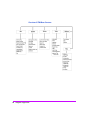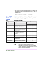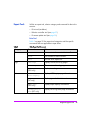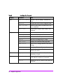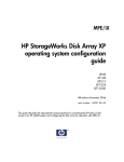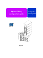
1
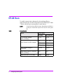
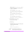
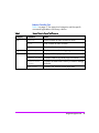
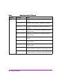
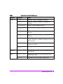
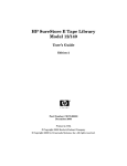
hp tape library configuration guide August 2001 configuration and diagnostic 2 hp tape library configuration guide contents Configuration 3 Configuring the Host System3 Windows NT4 Sun Solaris 5 HP-UX Hosts 6 Installing the Pass-Through Driver7 HSC or PCI Pass-Through Driver Installation8 Creating a Device File for the Robotics Controller8 Verifying the Installation10 MPE/iX Hosts11 Verifying the Connection 15 Diagnostics 17 Diagnostic support tools17 HP Library & Tape Tools18 Support Tools Manager (STM)19 Performing Operations21 Using the STM Tools21 Reviewing Logs 22 Types of STM Tools for Tape Libraries24 Expert Tools 25 Sysdiag 31 SCSITAC Sections32 SCSIDLT Sections 32 1 2 Configuration 1 Configuring the Host System Once the library is connected to a host, the Windows NT, Sun Solaris, HP-UX, and MPE/iX operating systems must be configured to recognize it. The procedures are different, depending on the host system. Configuring the Host System 3 Windows NT For Windows NT operating systems, perform the following operating system configurations: • Install the appropriate host bus adapter(s) • Install the corresponding drivers for the interface card(s) • Install the backup software To verify the installation, look for the library and drive after powering up the host. • Go into Settings -> Control Panel -> SCSI Adapter • You can also check your installation on Windows NT with HP diagnostic utilities available from www.hp.com/go/support. See the Downloads and Drivers section for your library model. Run a test backup to ensure that all components are properly configured. 4 Configuring the Host System Sun Solaris For Sun Solaris operating systems, perform the following operating system configurations: • Install the appropriate host bus adapter(s) • Install the corresponding drivers for the interface card(s) • Install the backup software To verify the installation, look for the library and drive after powering up the host. 1. Close all open applications and exit the Common Desktop Environment (CDE). 2. Type “init 0” at any prompt. This will shut down all processes, and take you to the OpenBoot PROM. 3. Type “reset”. 4. At the OK prompt, type “probe-scsi-all”. Run a test backup to ensure that all components are properly configured. Configuring the Host System 5 HP-UX Hosts To enable communication between the host and tape library, appropriate drivers must be configured into the HP-UX kernel. Table 1 shows which drivers are necessary for each device. NOTE Table 1 Some drivers have different names, depending on whether or not they are listed in the output of an ioscan or in the system file. Drivers Needed Device In ioscan In system file c720 c720 fcp fcT1_fcp fcT1 fcT1 fcT1_cntl fcT1_cntl Fibre Channel Bridge or Multiplexer fcpmux fcpmux Tape Library Robotics Controller (HSC or PCI Bus) sctl sctl Tape Driver (HSC or PCI Bus) stape stape SCSI Host Bus Adapter (HSC or PCI Bus) Fibre Channel Host Bus Adapter 6 Driver Name Configuring the Host System If these drivers are already installed into the kernel, upon system boot they will automatically be associated with the hardware that they control. However, if drivers are missing, they must be installed. For more information on installing Fibre Channel drivers, refer to the HP Fibre Channel Mass Storage Adapter Service and User Manual (A3636-90002). A pass-through driver is used to manage the robotics controller. Since this driver is not dedicated for this particular device, it must be manually installed. The following sections describe this process: • Installing the pass-through driver (below) • Creating a device file for the robotics controller (page 8) • Verifying the installation (page 10) Installing the Pass-Through Driver Class I bc 0 bc 1 ba Obtain information about the peripherals attached to the system: ioscan -f The screen should look similar to the following: H/W Path Driver S/W State H/W Type Description root CLAIMED BUS_NEXUS 8 bc CLAIMED BUS_NEXUS Pseudo Bus Converter 0 8/0 GSCtoPCI CLAIMED BUS_NEXUS PCI Bus Bridge GSCtoPCI ext_bus 1 8/0/2/0 c720 CLAIMED INTERFACE Ultra Wide SCSI target 3 8/0/2/0.0 tgt CLAIMED DEVICE autoch 2 8/0/2/0.0.0 schgr CLAIMED DEVICE target 4 8/0/2/0.1 tgt CLAIMED DEVICE tape 2 8/0/2/0.1.0 stape CLAIMED DEVICE target 5 8/0/2/0.2 tgt CLAIMED DEVICE tape 4 8/0/2/0.2.0 stape CLAIMED DEVICE HP C7200-8000 QUANTUM DLT8000 QUANTUM DLT8000 Configuring the Host System 7 NOTE HSC or PCI Pass-Through Driver Installation HP C7200-8000 is used only as an example. The actual ioscan output will reflect the product number of the library you are configuring. The following procedure assumes the use of a SAM terminal mode. In X-windows (GUI) mode, use the mouse button to select an option. 1. Run SAM. 2. Select Kernel Config, and press Return. 3. Select Drivers, and press Return. 4. Select sctl. NOTE If Current State is “In,” proceed to Creating a Device File for the Robotics Controller. Otherwise, continue with the next step. 5. From the Menu Bar, select Actions. Select Add Drivers to Kernel, and press Return. 6. From the Menu Bar, select Actions. Select Create New Kernel, and press Return. 7. At the Are you sure prompt, respond Yes. Press Return. 8. After the status messages, select OK. Press Return. The system reboots. Creating a Device File for the Robotics Controller 1. Use the mknod command to create a device file to access the robotics controller. The command syntax is: /user/sbin/mknod /dev/scsi/<devfilename> c <majornum> <minornum> • <devfilename> is the user-defined name of the device file. • <majornum> is the character major number from the lsdev command. • <minornum> is the minor number in the format 0xIITL00; where II is the two-digit card instance number in hexadecimal; T is the target SCSI ID number; L is the LUN number, and 00 is reserved. 8 Configuring the Host System 2. Determine the value for <majornum> by executing the following command for robotics attached to an HSC or PCI adapter: lsdev -d sctl The output resembles the following: HSC or PCI Character Block Driver Class 203 -1 sctl ctl Determine the value for <minornum> using the ioscan command. The applicable lines in the ioscan output are those that refer to the controller (contains the product name in the Description field) and to the adapter (contains the ext_bus in the Class field). For the HSC or PCI adapter, the ioscan output for the schgr driver can differ in two ways, though either indicates successful device file creation. • If the schgr driver is configured on the system, this driver appears to be associated with the library. The output would resemble the following: Class I H/W Path Driver S/W State H/W Type Description autoch 0 10/4/4.6.0 schgr CLAIMED DEVICE HP C7200-8000 • If the schgr driver is not configured on the system, no driver appears to be associated with the library. The ioscan output line resembles: Class I H/W Path unknown -1 10/4/4.6.0 Driver S/W State H/W Type Description UNCLAIMED DEVICE HP C7200-8000 Configuring the Host System 9 Verifying the Installation Confirm that the communications path to the robotics controller is functional: 1. Compile the SCSI I/O test program: cc /usr/contrib/src/scsi_io.c. -o/usr/contrib/ bin/scsi_io 2. Run the SCSI I/O test program, using the device file created during installation. For example, if the device file name is /dev/ rmt/HPA1234, the command would be: /usr/contrib/bin/scsi_io /dev/scsi/HPA1234 If the robotics is correctly configured, the following appears: the thing claims to be: HP C7200-8000 NOTE 10 Configuring the Host System HP C7200-8000 is used only as an example. The actual ioscan output will reflect the product number and firmware revision of the library you are configuring. MPE/iX Hosts Requirements Libraries require additional Legato NetWorker Server software that runs on either an HP Intelligent Server or an NT Server. The HP 3000 must be a Legato Networker Storage Node. Configuring the Host The example below illustrates the steps needed to configure the library on MPE/iX. NOTE This example illustrates the driver binding, but is not optimized for performance since it shows the entire library on a single differential bus. The library ID of A4669A is used only as an example. The actual RUN MAPPER output reflects the product number of your library. 1. Power on the library and host. Run ODE at the ISL prompt: ISL>ODE 2. Identify the device path through RUN MAPPER: ODE> RUN MAPPER ***STARTING EXECUTION OF MAPPER**** Processor Identification: ... I/O Configuration: Type HW SW Revisions Path Component Name ID Mod Mod Hdwr Firm ... /4/4 HP-PB Fast Wide SCSI . . . /4/4.0.0 A4669A . . . Configuring the Host System 11 /4/4.1.0 /4/4.2.0 /4/4.3.0 /4/4.4.0 DLT8000 DLT8000 DLT8000 DLT8000 . . . . . . . . . . . . 3. Boot the system. At the MPE prompt, run sysgen and start the io section: sysgen SYSGEN version E . . . sysgen> io ** IO configurator commands ** 4. If not already configured, configure the differential card and the pseudo/target level of the SCSI path: io> io> io> io> io> io> apath apath apath apath apath apath 10/4/4 id=HP28696A 10/4/4.0 id=pseudo 10/4/4.1 id=pseudo 10/4/4.2 id=pseudo 10/4/4.3 id=pseudo 10/4/4.4 id=pseudo 5. Configure the robotics controller and the drives (the pass-thru driver): io> adev 30 id=HPA4669A path=10/4/4.0.0 io> adev 31 id=DLT8000 path=10/4/4.1.0 mode=autoreply io> adev 32 id=DLT8000 path=10/4/4.2.0 mode=autoreply io> adev 33 id=DLT8000 path=10/4/4.3.0 mode=autoreply io> adev 34 id=DLT8000 path=10/4/4.4.0 mode=autoreply 6. Verify the bindings between PATH, LDEV number, ID, PMGR (device drivers), and LMGR attributes for each device configured. 12 Configuring the Host System a. Verify the binding for the device adapter (the fw/differential dam): io> lpath 10/4/4.0.0 PATH: 10/4/4 LDEV: ID: HP28696A TYPE: DA PMGR: FWSCSI_DAM PMGRPRI: 6 LMGR: MAXIOS: 0 Repeat this step for lpath 10/4/4.1, 4.2, 4.3, and 4.4. b. Verify the binding for the targets (the transparent dm): io> lpath 10/4/4.0 PATH: 10/4/4.0 LDEV: ID: PSEUDO TYPE: DA PMGR: TRANSPARENT_MGR PMGRPRI: 6 LMGR: MAXIOS: 0 Repeat this step for lpath 10/4/4.1, 4.2, 4.3, and 4.4. c. Verify the binding for the robotics controller (the pass-thru driver): io> lpath 10/4/4.0.0 PATH: 10/4/4.0.0 LDEV: 30 ID: HPA4669A TYPE: MOSAR_AC PMGR: MO_SCSI_PTHRU_DM PMGRPRI: 10 LMGR: LOGICAL_DEVICE_MANAGER MAXIOS: 0 Repeat this step for lpath 10/4/4.1, 4.2, 4.3, and 4.4. d. Verify the binding for the tape drives (the differential tape dm): io> lpath 10/4/4.1.0 PATH: 10/4/4.1.0 LDEV: 31 ID: DLT8000 TYPE: TAPE PMGR: SCSI_TAPE2_DM PMGRPRI: 10 LMGR: LOGICAL_DEVICE_MANAGER MAXIOS: Configuring the Host System 13 Repeat this step for lpath 10/4/4.1, 4.2, 4.3, and 4.4. e. To configure the Storage Node on the NetWorker server, verify the ldev specifications: io> Idev 30/34 LDEV: 30 DEVNAME: OUTDEV: 0 MODE: ID: HPA4669A RSIZE: 128 DEVTYPE: MOSAR_AC PATH: 10/4/4.0.0 MPETYPE: 24 MPESUBTYPE: 4 CLASS: LDEV: 31 DEVNAME: OUTDEV: 0 MODE: ID: DLT8000 RSIZE: 128 DEVTYPE: TAPE PATH: 10/4/4.1.0 MPETYPE: 24 MPESUBTYPE: 8 CLASS: TAPE ... LDEV: 34 DEVNAME: OUTDEV: 0 MODE: ID: DLT8000 RSIZE: 128 DEVTYPE: TAPE PATH: 10/4/4.4.0 MPETYPE: 24 MPESUBTYPE: 8 CLASS: TAPE 7. Save the configuration changes as follows: a. Hold the configuration changes: io> hold b. Exit the io section: io> exit c. If you have followed the local convention for backing up the configuration file, keep the changes: sysgen> keep keeping to group CONFIG.SYS Purge old configuration (yes/no)?y CAUTION 14 Configuring the Host System Check with the system administrator to ensure you can keep the changes to the configuration file. d. Exit sysgen and reboot according to local convention: sysgen> exit Verifying the Connection Additional information regarding the configuration and verification of libraries is provided in the Legato NetWorker Installation Guide (MPE/iX version) for the Networker Storage Node product. Configuring the Host System 15 16 Configuring the Host System Diagnostics 2 Diagnostic support tools The following external support tools are available for the library: • HP Library & Tape Tools • Support Tools Manager • Sysdiag Diagnostic support tools 17 HP Library & Tape Tools With HP Library & Tape Tools installed on your host computer, you can do the following: • Identify all SCSI and Fibre Channel devices connected to your system • View detailed configuration, identification, inventory, and drive information for the library • Easily update library and drive firmware • Run advanced diagnostic tests, including connectivity, read/write, media validation, and testing library functionality • View library and drive error logs • Generate a detailed support file that can be emailed or faxed to your support representative for analysis The HP Library & Tape Tools diagnostic provides an intuitive graphical user interface with integrated context-sensitive help. It can be downloaded free of charge from http://www.hp.com/support/ TapeTools. 18 Diagnostic support tools Support Tools Manager (STM) STM is the primary HP-UX support tool. Though this document provides general information about STM, more information is available through the following website: • http://docs.hp.com/ Select Systems Hardware, Diagnostics & Monitoring. Select Online Diagnostics (STM). There are three user interfaces, all in /usr/sbin/stm/ui/bin/: • xstm: The X Windows interface • mstm: The menu interface • cstm: The command line interface Diagnostic support tools 19 Overview of STM Menu Structure 20 Diagnostic support tools Performing Operations There are three basic operations in STM: 1. To select a device or devices: • In xstm, click on the device icon. • In mstm, move the cursor over the device, and press <SPACE>. 2. To run a tool: Tools -> <tool> -> Run 3. To view logs after the tool completes: Tools -> <tool> -> <log> Using the STM Tools • The Information tool creates an information log that contains firmware revisions and other useful device data. After the tool has created the log, you must then display it. Tools -> Information -> Run • The Verifier tool ensures the device is accessible by the operating system. Tools -> Verify -> Run • The Exerciser tool stresses the device. Tools -> Exercise -> Run • The Diagnostic tool attempts to isolate a hardware problem to a Field Replaceable Unit (FRU). Tools -> Diagnose -> Run • The Expert tool allows the user to interactively perform operations on the device. Tools -> Expert Tool -> Run Diagnostic support tools 21 • The Firmware Update tool allows the user to interactively download new firmware to the device. Tools -> Firmware Update -> Run • The Utilities tool is not tied to one device and includes: — LogtoolTools -> Utility -> Run... -> logtool — Copyutil is used to copy disk data to another disk to replace a bad disk. Tools -> Utility -> Run... -> copyutil • The Current Device Status tool provides general information about a device and what tools are available for it. Select the device(s). Device -> Current Device Status Reviewing Logs STM saves detailed information in several logs: • The Tool Activity Log contains testing details and errors for a specific tool on a device. Review this log when a tool does not complete successfully. • Select device(s). Tools -> <tool> -> Activity Log • The Tool Failure Log contains hardware failure information. Review this log if a tool does not complete successfully. • Select device(s). Tools -> <tool> -> Failure Log • The Information Log contains information gathered by information tools. Review this log after running an information tool. 22 Diagnostic support tools • Select device(s). Tools -> Information -> Information Log • The System Activity Log contains error information that is logged by the diagmond daemon. Review this log if problems occur when initiating tools, viewing log files, connecting to a UUT, etc. System -> System Activity Log NOTE If the UI cannot connect to the UUT, use File -> Administration -> Local -> UUT Logs -> System Activity Log. • The Map Log contains information and errors logged while scanning the system hardware. Review this log if the hardware map seems incorrect. System -> Map Log NOTE If the UI cannot connect to the UUT, use File -> Administration -> Local UUT Logs -> Map Log. • The UI Activity Log contains errors logged by the UI. Review this log when errors occur that prevent the UI from functioning correctly. File -> UI Activity Log • The Diagnostic Daemon Log contains information logged by diagnostic daemons, such as memlogd and diaglogd. Review these logs if system or memory error logging does not seem to be functioning properly. System -> Daemons -> Daemon Activity Log... • The Syslog contains information and errors logged by a variety of HP-UX programs. Review this log if diagmond does not start up. File -> Administration -> Local UUT Logs -> syslog Diagnostic support tools 23 • The OS Error Log contains information logged by I/O drivers and other operating system components. Review this log to check for hardware errors. Tools -> Utility -> Run... -> logtool Types of STM Tools for Tape Libraries Table 4 Table 4 on page 24 shows which types of STM tools are supported on the robotic and tape drive components of the library. Not all commands are supported on all libraries. Supported Tool Characteristics Tool Type Description Supported For Drives Robotics X Information tools Provides quick access to information about a device X Verifiers Provides a quick verification that a device is properly connected and functional X Exercisers Stresses the hardware and assists in reproducing intermittent problems X Diagnostics Tests a device, and isolates a failure to the most likely FRU X X Expert tools Interactive tool that assists in troubleshooting X X Firmware update tools Interactive tool that updates the firmware X X NOTE 24 Diagnostic support tools Within STM, the robotics component of a library is represented with an icon or text identifier of SCSI Media Changer. The tape drive is represented with an icon or text identifier indicating the type of drive. Expert Tools Within an expert tool, select a category and command for the tool to execute: • Drive tool (see below) • Robotics controller tool (see page 27) • Firmware update tool (see page 30) Drive Tool Table 5 on page 25 lists expert tool categories and the specific commands that are applicable to tape drives. Table 5 Drive Expert Tool Command Category Command Effect File Save As Save contents of menu window to a file. Print Print contents of menu window. Exit Exits the drive expert tool. View Logs Displays various drive log pages. Clear Logs Clears various drive log pages. Pull Trace Logs (DDS only) Displays trace logs. Describe or SCSI Inquiry Displays SCSI Inquiry page information. Drive info (DLT only) Displays general drive information Tape Info (DDS only) Displays tape capacity information. System/Device Info (DLT only) Displays drive log sense page information Logs Info Diagnostic support tools 25 Table 5 Drive Expert Tool Command Category Command Effect Tests Test Unit Ready Performs “Test Unit Ready” command on drive. Selftest Executes the drive’s built-in diagnostic tests. Tape Validate Reads a suspect tape until data ends or an error is detected. Write Test Writes data to a tape, reads it back, and compares. Tape Copy Performs a tape-to-tape copy. Load Tape Performs a load sequence. Unload Tape Performs an unload sequence. Rewind Rewinds to the beginning of a tape. Mode Sense Displays user selected mode page data. Mode Select Allows user to change selected mode select settings. Media Removal Prevents or allows media removal. Data capture Runs the “tape_capture -D -m” command and displays the results. Options Display Format Displays data as either raw hex, decoded format text, or both. Help General Help Brings up the dialog box with various help topics about the expert tool command. Version Displays the version number of the expert tool command. Utility 26 Diagnostic support tools Robotics Controller Tool Table 6 on page 27 lists expert tool categories and the specific commands applicable to the library robotics. Table 6 Robotic Controller Expert Tool Command Category Command Effect File Save As Saves contents of menu window to a file. Print Print contents of menu window. Exit Exits the robotics expert tool. Logs View Logs Displays various robotics log pages. Info Describe Displays SCSI inquiry page information. Support Ticket Displays robotics log sense page information. Read Elememt Status Displays the status and inventory of robotics storage elements. Mode Sense Displays user selected mode page data. Diagnostic support tools 27 Table 6 Robotic Controller Expert Tool Command Category Command Effect Tests Selftest Performs power-on self test of robotics and reports results. Test Unit Ready Performs “test unit ready” command on robotics. Wellness Performs a wellness test of robotics and reports results. Exercise Mech Performs an “exercise mech” diagnostic test and reports results. Empty Drives Performs an “empty drives” diagnostic test and reports results. Fill Picker Performs a “fill picker” diagnostic test and reports results. Empty Picker Performs an “empty picker” diagnostic test and reports results. Vertical Encoder Performs a “vertical encoder” diagnostic test and reports results. Random Moves I (May not be supported, depending on library model.) Performs “random moves I” diagnostic test. Random Moves II (May not be supported, depending on library model). Performs “random moves II” diagnostic test. 28 Diagnostic support tools Table 6 Robotic Controller Expert Tool Command Category Command Effect Utility Rezero Performs “rezero” command on robotics. Position to Element Performs “position to element” command on robotics. Move Medium Moves 1 tape cartridge in library. Exchange Medium Moves 2 tape cartridges in library. Init Element Status Performs “initialize element status” command on robotics. Set Drive Status Changes on-line drive repair status of tape drives in library. Recalibrate (May not be supported, depending on library model.) Performs a “recalibrate” diagnostic test and reports results. Data Capture Runs the “tape_capture -D -m” command and displays the results. Set Serial Number Changes the electronic serial number of robotics. Options Display Format Displays data as either raw hex, decoded format text, or both. Help General Help Brings up a dialog box with various help topics about expert tool. Version Displays the version number of expert tool. Diagnostic support tools 29 Firmware Update Tool When started, the firmware update tool will examine the firmware revision of the current SCSI device, and then search the directory /var/tmp for firmware files that are compatible with the device. The internal headers of any firmware files present in this directory will be checked. If compatible files are found, it will select the most current version and pop up a dialog box asking if you want to update firmware immediately. If you select [Start Update], the tool will update the device firmware and display text messages indicating the status in the firmware update menu window. If no files are found (or no compatible files are found), it will display an error message stating that no compatible files were found, followed by a dialog box prompting the user to change the directory path where the tool searches for firmware files. If you have enabled the licensed firmware update tool, you can start it by selecting [Utility], followed by [Advanced Menu] from the firmware update menu bar. A list of several compatible firmware files will be displayed in the dialog box that pops up. You can select from a list of files, and then select [Start Update] to begin the firmware update process. NOTE 30 Diagnostic support tools After updating firmware, allow time for the device to initialize and test itself. Power cycling the device before this process has completed may result in product failure and the inability to perform further updates. Sysdiag NOTE Version 5.5 and 6.0 are supported for the libraries, but use the STM tool for version 6.5 (see Support Tools Manager (STM) on page 19). Sysdiag is the MPE/iX support tool, and provides a consistent user interface for support of tape libraries, as well as many other types of peripheral devices. Sysdiag is a licensed-use tool, so a user must first know and enter a diagnostics password. Enter a password by typing in the following command at the MPE/iX prompt: :suplicen Use of sysdiag also assumes knowledge of the ldevs at which the components to be supported are located. To start sysdiag, type in the following command at the MPE/iX prompt: :sysdiag This command will bring up the Diagnostic User Interface (DUI) prompt. Two diagnostics are available to support DLT libraries: • SCSITAC (SCSI Tape Autochanger) for support of library robotics • SCSIDLT for support of DLT tape drives SCSITAC and SCSIDLT are divided into parts called “sections.” To use either of these diagnostics, enter the diagnostic name, ldev where the device is located, and section to be run at the UI prompt. For example: DUI> scsitac ldev=6 sc=4 Diagnostic support tools 31 SCSITAC Sections SCSITAC contains three sections: • Section 1: Verification Trouble Tree • Section 2: Hardware Trouble Tree • Section 4: Interactive Sections 1 and 2 perform tests on the library, report results, and return to the DUI prompt. Section 4 provides users with a SCSITAC prompt, which accepts the following commands (Table 7). Table 7 SCSIDLT Sections SCSITAC Interactive Commands Command Function devreset Performs a SCSI device reset. download Downloads firmware. The user may place the download file anywhere on the host system. The download command will prompt the user to enter the fully qualified filename. exit Exits the interactive section. inquiry Performs a SCSI inquiry. help Displays this list of commands. tur Performs a SCSI Test Unit Ready. SCSIDLT contains four sections: • Section 1: Verification Trouble Tree • Section 2: Hardware Trouble Tree • Section 3: Destructive Hardware Trouble Tree • Section 4: Interactive Sections 1, 2, and 3 perform tests on the library, report results, and return to the DUI prompt. 32 Diagnostic support tools Section 4 provides the user with a SCSIDLT prompt, which will accept the following commands (Table 8 on page 33). Table 8 SCSIDLT Interactive Commands Command Function blocklimit Displays the maximum and minimum record lengths. cartridge Identifies tape type of loaded cartridge. clearlogs Clears error logs. compression Enables or disables compression. devreset Performs a SCSI device reset. download Downloads firmware. The user may place the download file anywhere on the host system. The download command will prompt the user to enter the fully qualified filename. exit Exits the interactive section. inquiry Performs a SCSI inquiry. help Displays this list of commands. logs Displays log pages. motioncheck Performs basic tape movement functions. prevallow Provides capability to prevent or allow tape removal. rewind Rewinds tape to BOT. suspend Suspends the current diagnostic process. tur Performs a SCSI Test Unit Ready. workout Performs a Write/Read test with data compression. Diagnostic support tools 33 34 Diagnostic support tools