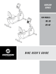
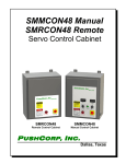
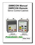
1
0610 High Torque Servo Motor Series Manual P USH C ORP, I NC. Dallas, Texas January, 2007 ! CAUTION ! Do NOT apply air pressure to release the Collet while the servo motor is rotating. The servo motor spindle must be FULLY STOPPED before actuating the Collet. Do NOT overheat the servo motor. Supply the motor cooling water to maintain a temperature below 176 F (80 C). Do NOT start or stop the servo motor instantaneously. Doing so will damage the motor and power amplifier. All PushCorp, Inc. electrical cables are rated for high twist and flex robotic applications with a minimum cable bending radius specification of 125mm (5 in). Cable damage resulting from failure to abide by this specification will not be covered under warranty. P USH C ORP, I NC. 0610 Servo Motor Series Manual Table of Contents 1.0 LIMITED WARRANTY...........................................................................................1 2.0 GENERAL OVERVIEW..........................................................................................3 3.0 INSTALLATION & OPERATION............................................................................4 3.1 Mounting the 0610........................................................................................................................... 4 3.1.1 Mounting to an AFD1100/80......................................................................................................... 4 3.1.2 Mounting Directly to a Robot........................................................................................................ 7 3.2 Media and Tool Presentation........................................................................................................... 7 3.3 Tool and Media Specification.......................................................................................................... 8 3.3.1 STC0610 & SM0610 Tool Shaft Specification..............................................................................8 3.3.2 STC0610-BT40 Toolholder Specification...................................................................................10 3.4 SM0610 Collet Operation.............................................................................................................. 12 3.4.1 SM0610 Collet Assembly and Removal.....................................................................................12 3.5 Pneumatic Connection.................................................................................................................. 13 3.6 Electrical Connections................................................................................................................... 15 3.7 Motor Cooling................................................................................................................................ 16 3.8 Monitoring Motor Temperature...................................................................................................... 16 3.9 Motor Acceleration/Deceleration................................................................................................... 18 4.0 TECHNICAL SPECIFICATIONS..........................................................................19 P USH C ORP, I NC. 0610 Servo Motor Series Manual 1 1.0 Limited Warranty Duration: One year from date of delivery to the original purchaser. Who gives this warranty (warrantor): PushCorp, Inc. Telephone: (972) 840-0208 Corporate Address: P. O. Box 181915 Dallas, Texas 75218 Shipping Address: 3001 W. Kingsley Rd. Garland, Texas 75041 Who receives this warranty (purchaser): The original purchaser (other than for purposes of resale) of the PushCorp, Inc. product What products are covered by this warranty: Any PushCorp, Inc. industrial manufactured by the Warrantor. equipment or accessory supplied or What is covered under this warranty: Defects in material and/or workmanship which occur within the duration of the warranty period. What is NOT covered in this warranty: A. IMPLIED WARRANTIES, INCLUDING THOSE OF MERCHANT-ABILITY AND FITNESS FOR A PARTICULAR PURPOSE ARE LIMITED TO ONE YEAR FROM THE DATE OF ORIGINAL PURCHASE. Some states do not allow limitations on how long an implied warranty lasts, so the above limitations may not apply to you. B. ANY INCIDENTAL, INDIRECT, OR CONSEQUENTIAL LOSS, DAMAGE or EXPENSE THAT MAY RESULT FROM ANY DEFECT, FAILURE, MALFUNCTION OF THE PUSHCORP, INC. PRODUCT. Some states do not allow the exclusion or limitation of incidental or consequential damages so the above limitation or exclusion may not apply to you. C. Any failure that results from an accident, purchaser's abuse, neglect, unauthorized repair or failure to operate the products in accordance with the instructions provided in the owner's manual(s) supplied with the product. Responsibilities of the Warrantor under this warranty: Repair or replace, at Warrantor's option, products or components which have failed within the duration of the warranty period. Copyright PushCorp, Inc. 2014. All rights reserved. P USH C ORP, I NC. 0610 Servo Motor Series Manual 2 Responsibilities of the purchaser under this warranty: A. Deliver or ship the PushCorp, Inc. product or component to PushCorp, Inc. Service Center, Dallas, TX. Freight and insurance costs, if any, must be borne by the purchaser. B. Use reasonable care in the operation and maintenance of the product as described in the owner's manual(s). When warrantor will perform repair or replacement under this warranty: Repair or replacement will be scheduled and serviced according to the normal work flow at the service center, and depending on the availability of replacement parts. Purchasers requiring quicker repair may receive such with payment of a PushCorp, Inc. predetermined expediting fee. This Limited Warranty gives you specific legal rights and you may also have other rights which vary from state to state. Copyright PushCorp, Inc. 2014. All rights reserved. P USH C ORP, I NC. 0610 Servo Motor Series Manual 3 2.0 General Overview The PushCorp 0610 Servo Motor is capiable of continuously producing 10 horsepower, and spinning up to 6000 rpm. The 0610 series includes three versions; an SM0610 manual collet, an automatic version with a collapsing collet (STC0610) and another automatic version which clamps a BT40 toolholder (STC0610-BT40). The 0610 series utilizes identical motor windings, and power amplifiers. Differing only in a few physical dimensions and how they secure the media. Each of these motors provide a convenient and effective means to spin and/or change any number of different media types to support a fully automated workcell. The SM0610 has a manually tightened collet that is a cost-effective alternative to the automatic version. The SM0610 uses the same motor winding and housing as the STC0610, but without the automatic clamping mechanism. The manual Collet is a standard ER-40 series collet designed to clamp a 1 inch (25.4 mm) diameter Tool Shaft. The user may choose different sized collets in the ER-40 series, ranging from 1/8 - 1 inch (2 - 30 mm). The STC0610 Series has two automatic tool changing versions, each acutating pneumatically to clamp the shaft or toolholder. They are comprised of four primary components: a high-torque Servo Motor, a pneumatic actuator, high force Bellville springs, and a component to clamp a Tool Shaft/Toolholder. The STC version uses a drawbar to pull the Collet/Gripper in. High force Bellville springs located at the back of the Servo Motor Housing tension the drawbar. Energizing the large pneumatic actuator, located in the Clamping Housing, opens the Collet/Gripper. During pressurization the cylinder contacts the Bellville springs and compresses them to drive the Collet/Gripper out, releasing the Tool Shaft/Toolholder. There is no mechanism to forcibly eject the Tool Shaft/Toolholder from the Collet, so gravity or a capturing mechanism must be used. The STC0610 version uses a PushCorp propriatary collapsing Collet to lock around a Tool Shaft. The STC0610-BT40 uses a 40 taper to grip a standard BT40 toolholder. This design locks the toolholder in the 40 tapered shaft and resists large pull out forces. Neither shaft has locking keys, so motor indexing for tool change is not required. The STC0610 motors are fail-safe, in that no air pressure is required to clamp the Tool Shaft/Toolholder. Therefore the Tool Shaft/Toolholder will remain held in the Collet/Gripper even when the air pressure is un-expectantly lost. Likewise, applying air pressure to a single input port via a simple manual or electrically operated valve opens the Collet/Gripper and releases the Tool Shaft/Toolholder. Finally, clever mechanical design always isolates the motor bearings from the drawbar tension. This greatly improves reliability by allowing the motor bearings to never be subject to any clamping forces. Each member of the 0610 Series uses sealed bearings to insure a long life. The 0610 bearings have additional contamination protection from a PushCorp proprietary contact shaft seal. This special seal eliminates the need for constant purge air. During operation the 0610 generates considerable heat due to the high torque and compact size of the motor. Water-cooling is required to keep the unit within the internal temperature operating range. Excessive operating temperatures will significantly reduce the life of the motor. The motor should never be allowed to exceed a temperature of 176 F (80 C). Continuously operating the unit above 176 Copyright PushCorp, Inc. 2014. All rights reserved. P USH C ORP, I NC. 0610 Servo Motor Series Manual 4 F (80 C) will cause the rotor to de-magnetize and the bearings to fail. High temperatures will also cause the O-rings that seal the cooling water channels to fail, possibly filling the motor with water. PushCorp has provided flow through water cooling on the motor to allow high duty cycles without overheating. Simple reliable construction combined with high torque and precision speed controlled servo technology make the PushCorp 0610 Servo Motors a rugged, stateof-the-art tool capable of providing flexible, cost-effective operations. 3.0 Installation & Operation 3.1 Mounting the 0610 3.1.1 Mounting to an AFD1100/80 The 0610 Series motors are designed to attach directly to the Carriage of any PushCorp AFD1100/80 or AFD1200/90 Force Device. There are three standard attachment options. For the Parallel-Axis configuration, shown in Figure 1, the 0610 attaches to the AFD Carriage with two brackets and four (4), M8x1.25x25mm, Socket Head Cap Screws. The 0610 is positioned on the Carriage with the Foot Bracket while the Front Bracket is attached to the forward mounting holes. The Clamping Screw on the Front Bracket should be loose to allow sliding movement along the motor. Attach the Foot Bracket to the Clamping Housing (Mounting Plate for the SM0610) using two (2), M8x1.25 Socket Head Cap Screws. When the desired position is achieved secure the brackets to the Carriage, and tighten the Clamping Screw. The M8x1.25, Socket Head Cap Screws, must be the proper length and tightened to the torque specified in Section 4.0. Copyright PushCorp, Inc. 2014. All rights reserved. P USH C ORP, I NC. 0610 Servo Motor Series Manual 5 By rotating the 0610 90 degrees to the Carriage, a Cross-Axis configuration can be achieved as shown in Figure 2. The unit is attached using the same fasteners and methodology as the Parallel-Axis configuration. To attach the 0610 to an AFD in a Perpendicular-Axis configuration, position the Clamping Housing/Mounting Plate over the Carriage as shown in Figure 3. Then secure the unit using four (4), M8x1.25 Socket Head Cap Screws. Tighten the fasteners to the torque specified in Section 4.0. CAUTION: Make sure that the M8x1.25 fasteners do not exceed a depth of 0.52” (13.3 mm) into the AFD Carriage Helicoils or damage will occur. C LAMPING SCREW (M8x1.25x25mm SOC KET HEAD C AP SCREW) C LAMPING HOUSING STC 0610 FRONT BRAC KET FOOT BRAC KET (2) M8x1.25 SOCKET HEAD C AP SC REWS AFD80 or AFD1100 (4) M8x1.25x25mm SOCKET HEAD C AP SC REWS Figure 1. 0610 Parallel-Axis Configuration Copyright PushCorp, Inc. 2014. All rights reserved. P USH C ORP, I NC. 0610 Servo Motor Series Manual 6 CLAMPING HOUSING C LAMPING SCREW (M8x1.25x25mm SOCKET HEAD C AP SCREW) STC 0610 FRONT BRACKET FOOT BRACKET (2) M8x1.25 SOCKET HEAD C AP SCREWS (4) M8x1.25x25mm SOCKET HEAD C AP SCREWS AFD80 or AFD1100 Figure 2. 0610 Cross-Axis Configuration AFD80 OR AFD1100 C LAMPING HOUSING STC 0610 (4) M8x1.25 SOCKET HEAD C AP SCREWS Figure 3. 0610 Perpendicular-Axis Configuration Copyright PushCorp, Inc. 2014. All rights reserved. P USH C ORP, I NC. 0610 Servo Motor Series Manual 7 3.1.2 Mounting Directly to a Robot For some processes compliance and force control are not required. The 0610 can be mounted directly to the robot and the system can be operated in position mode. This robotic system is equivalent to a 5-axis machining center with a very large work volume and lower positional accuracy. Certain product types and processes are well suited for a Robotic Machining Center (RMC). The 0610 Series can be attached to the robot mounting flange using an intermediate mounting plate. For direct mounting it is recommended that a breakaway clutch is installed. The breakaway clutch will help protect the motor in the event of a robot crash. Loads on the motor shaft of over 2500 lb (11200 N) radially and 1260 lb (5600 N) axially will damage the bearings. ROBOT BREAKAWAY C LUTC H OR ROBOT MOUNTING FLANGE MOUNTING PLATE FASTENERS (AS REQ'D) STC 0610 MOUNTING PLATE (4) M8x1.25 SOC KET HEAD C AP SC REWS Figure 4. STC0610 Direct Mounting To mount the 0610 Series, first attach the Intermediate Mounting Plate to the Robot Mounting Flange or to the Breakaway Clutch, per the manufacturer’s specifications. Once the Mounting Plate is secured, place the 0610 Series against the Intermediate Mounting Plate and install (4) four, M8x1.25 Socket Head Cap Screws. (See Figure 4.) Tighten the fasteners to the torque specified in Section 4.0. 3.2 Media and Tool Presentation Media and tool presentation refers to how various disks, drill bits, router bits, etc. are presented so that a robot may maneuver the STC0610 into position to grasp the Tool Shaft/Toolholder reliably. It is ultimately the user’s responsibility to provide a means to present the media and/or tooling in an effective and repeatable way for a given application. Copyright PushCorp, Inc. 2014. All rights reserved. P USH C ORP, I NC. 0610 Servo Motor Series Manual 8 TOOL SHAFT TAPERED HOLDER TOOL C RADLE DRUM C ARTRIDG E C HAMFER BIT DRILL BIT Figure 5. Sample media and tooling presentation scheme As shown above, in Figure 5, many types of media and tools may be accurately located in a Tool Cradle. A robot can then be taught approach paths and docking locations to reliably bring the STC0610 down over the Tool Shafts and grasp them. The STC0610 Collet allows 0.015 in. (0.38 mm) diametral clearance around the Tool Shaft when open. The Tool Shaft must have a taper that mates to a Tapered Holder mounted in the Tool Cradle. The Tapered Holder requires a slot to allow the Tool Shaft to pass through. 3.3 Tool and Media Specification 3.3.1 STC0610 & SM0610 Tool Shaft Specification The STC0610 and SM0610 are designed to grasp a 1 inch (25.4 mm) diameter steel shaft. Figure 8 shows the Tool Shaft dimensions required for the STC0610 and SM0610 to operate properly. Notice that the end of the Tool Shaft can be tailored to any needed configuration to attach to various disk back-up pads, drill bits, router bits, grinding stones, etc. To prevent interference between the Tool Shaft and the STC0610 Collet an 11° taper must be included. Tool Shafts should be manufactured from carbon or stainless steel with a hardness less than Rc40. The surface finish on the Tool Shaft Clamping Surface should be Ra 16 – 32. To accurately locate the Tool Shaft axially the front flat surface of the Collet can be used. This means that the Tool Shaft Clamping Surface and taper must be shorter than the Collet depth. When using the Collet face for positioning some form of compliance must be used on the Tool Cradle to prevent wedging the Collet in too tightly, or damaging the motor bearings. Copyright PushCorp, Inc. 2014. All rights reserved. P USH C ORP, I NC. 0610 Servo Motor Series Manual 9 2.400 [60.96] 1.732 [44.00] C OLLAPSING C OLLET STC0610 MOTOR SHAFT Figure 6. STC0610 Collet Drawing 2.437 [61.90] ER C OLLET SM0610 MOTOR SHAFT C OLLET NUT Figure 7. SM0610 Collet Drawing Copyright PushCorp, Inc. 2014. All rights reserved. P USH C ORP, I NC. 0610 Servo Motor Series Manual 10 2.300 [58.4] 1.600 [40.6] Ø1.000 ±.001 [Ø25.4] 11° END TO SUIT C USTOMER'S MEDIA R0.025 [R0.6] MAX. MAC HINED FLATS FOR TIG HTENING MEDIA THREAD TO MATC H MEDIA C LAMPING SURFAC E TAPER TO MATC H TAPERED HOLDER EXAMPLE OF C USTOMER SHAFT Figure 8. STC0610 & SM0610 Tool Shaft Drawing 3.3.2 STC0610-BT40 Toolholder Specification The STC0610-BT40 is designed to grip a BT40 toolholder without using the shaft locking keys. The motor relies on the frction in the taper to secure the Toolholder. No shaft locking keys means that the shaft does not needd to be indexed to a specific position to perform a tool change. The BT40 toolholder is a standard machine tool style and may be purchased from several sources including, MSC (www.msc.com), and J & L Industrial Supply (www.jlindustrial.com). The Customer can also make their own BT40 toolholder to handle special media (See Figure 9 for toolholder dimensions). The toolholder must be equipped with a Parlec (www.parlec.com) retention knob, part number 4020TRK, or equivalent. Figure 10 shows the Parlec retention knob with the required dimensions. Copyright PushCorp, Inc. 2014. All rights reserved. P USH C ORP, I NC. 0610 Servo Motor Series Manual 2.575 [65.41] 11 1.062 [27.01] 0.079 [2.01] M16x2 8.2989° 8.2971° Ø1.750 [44.45] Ø0.669 [16.99] 0.354 [8.99] 0.827 [21.01] C USTOMER C AN DESIG N END TO SUIT THEIR APPLIC ATIO N Figure 9. BT40 Toolholder Dimensions 2.126 1.141 0.905 Ø0.549 Ø0.746 75° M16x2 Figure 10. BT40 Retention Knob Copyright PushCorp, Inc. 2014. All rights reserved. P USH C ORP, I NC. 0610 Servo Motor Series Manual 12 3.4 SM0610 Collet Operation The Collet for the SM0610 is tightened and loosened manually. The Motor Shaft must be held using the Motor Shaft Flats, while the Collet Nut is turned, see Figure 14. Turning the Collet Nut forces the Collet into the Motor Shaft causing it to clamp around the Tool Shaft. Rotating the Collet Nut clockwise will tighten the Collet. To loosen the Collet, rotate the Collet Nut counter-clockwise. If the Collet is to be removed, continue rotating the Collet Nut counter-clockwise and the Collet Nut and Collet will come off together. The Collet is an ER Series (DIN 6499 Form B) Size 40. The recommended tightening torque for the Collet Nut is 128 lb.-ft. (175 N·m). CAUTION: Tightening toques greater than 160 lb.-ft. (220 N·m) will permanently deform the collet cavity of the toolholder. NOTE: A collet wrench RegoFix P/N 7111.40000, or equivalent, should be used to tighten the Collet Nut. 3.4.1 SM0610 Collet Assembly and Removal To assemble the Collet insert the Collet Groove into the Eccentric Ring of the Collet Nut at the mark on the bottom of the Collet Nut. Push the Collet in while rotating the Collet up, until it clicks in. See Figure 11. To remove the Collet, first unscrew the Collet Nut from the Motor Shaft. After the Collet Nut is unscrewed, press on the face of the Collet while simultaneously pushing sideways on the back of the Collet until it disengages from the Collet Nut. See Figure 11. COLLET GROOVE COLLET NUT ECCENTRIC RING MARK ON BOTTOM COLLET ASSEMBLY COLLET REMOVAL Figure 11. SM Collet Assembly and Removal Copyright PushCorp, Inc. 2014. All rights reserved. P USH C ORP, I NC. 0610 Servo Motor Series Manual 13 Improper assembly or removal of the Collet can permanently destroy the concentricity of the Collet and may result in a damaged Collet Nut. NOTE: Only attach Collet Nuts with correctly assembled Collets, to the Motor Shaft! Never place the Collet into the Motor Shaft without first assembling the Collet into the Collet Nut. NOTE: Never clamp oversized, or undersized, Tool Shafts! E.g., never use a 11-12mm Collet to clamp a 12.2mm Tool Shaft. Always use the corresponding Collet for the Tool Shaft being used. NOTE: Insert the Tool Shaft the full length of the Collet for best results, if possible. However, never insert the Tool Shaft less than 2/3 of the Collet bore length. Improper tool insertion can permanently deform the Collet and will result in excessive run-out. 3.5 Pneumatic Connection All STC versions of the 0610 require a dry, non-lubricated, filtered air supply, with a minimum pressure of 90 psi (6.2 bar) and a maximum pressure of 100 psi (6.9 bar). Failure to provide supply air to these specifications can degrade performance and will void any warranty repairs concerning pneumatic components. If the supply air pressure is too low then the unit will be unable to fully release the Tool Shaft/Toolholder. Exceeding the maximum air pressure could result in permanent damage to the STC. The pneumatic supply system should be configured as shown in Figure 12. A manual or electrically operated valve may be used to energize the STC for Tool Shaft/Toolholder release, but the valve must exhaust ALL line pressure when unenergized. An electrically operated pneumatic valve is normally used in an automated workcell. PushCorp highly recommends the installation of a Pressure Switch in the Supply Line to the STC. This switch should not allow the unit to start if there is any pressure in the Supply Line. Pressure in the line will cause internal components to come into contact. This will either cause the motor not to spin, or cause very high internal forces, eventually friction welding components together. 1/ 4" (6mm) UNC LAMP SUPPLY LINE AIR REGULATOR / PRESSURE G AUG E 90 psi (6.2 bar) MIN. 100 psi (6.9 bar) MAX. DRY, NON-LUBRIC ATED AIR SUPPLY SHUT-OFF VALVE 5µm FILTER PRESSURE SWITC H MANUAL OR ELEC TRIC ALLY OPERATED VALVE Figure 12. Pneumatic Connections Copyright PushCorp, Inc. 2014. All rights reserved. P USH C ORP, I NC. 0610 Servo Motor Series Manual 14 The STC0610 and STC0610-BT40 are provided with ¼ inch and 6 mm diameter tubing push-lock fittings for installation in the R 1/8 (Metric) Collet Unclamp Port located on the top of the Clamping Housing (See Figure 14). Remove the shipping plug and install the desired size push-lock fitting. If another type of fitting is desired, unscrew the existing fitting and replace it with any fitting having an R 1/8 (Metric) thread. Be sure to use a thread seal product and do not over tighten the fitting. The Unclamp Supply Line to the device should be 1/4 inch or 6 mm diameter flexible polyurethane tubing. The tubing should be routed to the device such that there are no kinks and that there is plenty of slack to allow for manipulator motion. Before inserting the tubing into the STC air fitting, open the Shut-Off Valve to blow out any contaminates which may be in the Unclamp Supply Line. The tubing can now be pushed into the self-locking fitting located on the Clamping Housing as shown in Figure 14. Charge the Unclamp Supply Line with compressed air and verify that there are no air leaks and that there is a minimum of 90 PSI (6.2 bar) at the STC. If a minimum air pressure cannot be achieved, then an auxiliary air compressor or booster pump must be installed. NOTE: PushCorp highly recommends the use of flexible polyurethane tubing as opposed to nylon tubing. This is because nylon tubing tends to crimp shut when it is bent. To remove the Unclamp Supply Line for service, make sure the air pressure is discharged, then while pushing inward on the fitting's plastic ring, simultaneously pull the tubing out. Cover or plug the self-locking fitting any time the Unclamp Supply Line is not connected. This will keep contaminants from entering. Copyright PushCorp, Inc. 2014. All rights reserved. P USH C ORP, I NC. 0610 Servo Motor Series Manual 15 3.6 Electrical Connections The 0610 servo motor has two electrical connections, the Motor Power and Motor Feedback (See Figure 14). If PushCorp supplies the cables and amplifier the tool should be easily connected to the amplifier. If the customer wishes to use their own cables and/or amplifier the pin-outs for the Motor Power and Motor Feedback connectors are shown below in Figure 13. The Collet release mechanism of the STC0610 relies solely on air pressure to operate; it requires no electrical connections. A M B N P L C K U R D V J T S E H F G B A C D FEEDBAC K C ONNEC TOR POWER C ONNEC TOR FEEDBAC K PIN-OUTS PIN SIGNAL A HALL + SUPPLY B HALL - SUPPLY C HALL C D HALL B HALL A E F THERMISTOR T THERMISTOR V SHIELD POWER PIN-OUTS PIN SIGNAL A MOTOR A B MOTOR B C MOTOR C D GROUND/SHIELD Figure 13. Electrical Connector Pin-outs CAUTION: Do not run the Motor Power Cable in close proximity to any feedback or control cables because of possible electrical noise problems. Copyright PushCorp, Inc. 2014. All rights reserved. P USH C ORP, I NC. 0610 Servo Motor Series Manual 16 3.7 Motor Cooling The 0610 Series has a compact, high torque, 10.0 Hp (7.5 kW) Servo Motor which requires water cooling. The motor is designed to operate below a temperature of 176 F (80 C). The optimal motor temperature range is 122 – 140 °F (50 – 60 °C). The 0610 contains cooling channels in the Motor Housing surrounding the motor stator. These channels allow efficient removal of the heat. The coolant enters and exits the Motor Housing through two Motor Cooling Ports as shown in Figure 14. Either of these Motor Cooling Ports can be used as an input, the other would then become an output A closed-loop water cooling system must be used and requires a separate cooling unit that circulates water through the Motor Housing to remove the heat. All of the coolant is recirculated in the system, and no continuous supply or discharge is required. A mixture of pure distilled water and a corrosion inhibitor is required such as DowTherm SR-1, or equivalent. Typical cooling units are comprised of a pump, water to air heat exchanger, and fan. These units are commercially available from several manufacturers (eg Miller Coolmate 3, www.millerwelds.com). The cooling unit should be sized based on the motor power output of 10 Hp (7.5 kW) with an overall motor efficiency of 90% and the motor load conditions. Again it is recommended to constantly monitor the motor temperature during operation to ensure that it does not overheat. NOTE: The life of the 0610 motor is directly related to the operational temperature, so proper cooling is critical. The 0610 Series is supplied with two 5/16” and 8 mm diameter tube push-lock fittings for installation in the Motor Cooling Ports. Remove the shipping plugs and install the desired size push-lock fittings. If another type of fitting is needed, replace the existing fitting with a fitting having an R 1/8 (Metric) thread. Be sure to use a thread seal product and do not over tighten the fitting. 3.8 Monitoring Motor Temperature As previously stated, the 0610 Series is designed to operate below a temperature of 176 °F (80 °C) and within an optimal range of 122-140 °F (50-60 °C). In many situations it is desirable to monitor the internal motor temperature to ensure that the maximum temperature rating is not exceeded, and that the optimal temperature range is maintained. To facilitate this, the 0610 Series has a thermistor that is imbedded in the motor windings. The thermistor connection is provided on the Motor Feedback Connector as shown in Figure 13. The thermistor temperature signal is a logarithmic function of the output resistance. The graph shown in Figure 15 illustrates the internal motor temperature verses the thermistor output resistance. In the graph, a temperature of 176 F (80 C) corresponds to a resistance of 2000 ohms. If the thermistor indicates a resistance of less than 2000 ohms then the motor should be immediately shut down before thermal damage occurs. The motor also contains a thermal cutoff switch. If the temperature exceeds 212 F (100 C) the motor will stop running until it has cooled off. This feature should not be Copyright PushCorp, Inc. 2014. All rights reserved. P USH C ORP, I NC. 0610 Servo Motor Series Manual 17 used to control the motor temperature. The thermal cutoff is designed to operate only when all other precautions have failed. STC0610 Thermistor Temp vs Resistance Characteristics 160 140 120 100 De gr ee 80 s C 60 40 20 0 0.1 1 10 Resistance (KOhms) 100 Semitec Type 203GT Thermistor Figure 14. Thermistor Chart Copyright PushCorp, Inc. 2014. All rights reserved. P USH C ORP, I NC. 0610 Servo Motor Series Manual 18 The following equation can be used to calculate the motor temperature based on the measured thermistor resistance: T 2.656 10 3 1 273.15 2.317 10 ln(R ) 1.752 10 7 ln( R) 3 4 R is resistance in Kohms ln() is the natural logarithm function (Base e) T is temperature in C 3.9 Motor Acceleration/Deceleration Servo Motors have the ability to start and stop very quickly. As long as the motor does not overheat or the amplifier exceed the allowable current input, the motor will continue to operate. The problem is that the motor and amplifier can experience excessive current spikes with rapid acceleration and declaration. Media or tooling with a large mass or large diameter (i.e., high moment of inertia) only increases the current surge. The amount of time allowed to reach the desired speed or stop will directly effect the life of the motor. PushCorp recommends a smooth, linear velocity ramp with a minimum period of one second be used to accelerate to full speed or to decelerate to zero speed. The minimum one-second-acceleration period must be increased if larger, higher inertia tools are used to prevent servo amplifier faults and avoid long-term damage. Copyright PushCorp, Inc. 2014. All rights reserved. P USH C ORP, I NC. 0610 Servo Motor Series Manual 19 4.0 Technical Specifications MOTOR SPECIFICATIONS: Supply Bus Voltage: 300 - 340 VDC (208 – 240 VAC Rectified) Power: 10.0 hp (7.5 kW) Continuous Stall Torque: 10.7 lb.-ft. (14.5 N·m) Minimum Speed: 60 RPM Maximum Speed: 6000 RPM Speed Regulation: 5% (Reversible) Weight: SM0610 - 52 lb (24 kg) STC0610 – 72 lb (32.6 kg) STC0610-BT40 – 82 lb (37.2 kg) Operating Temperature: Optimal: 122 – 140 F (50 – 60 C) Maximum: 176 F (80 C) Thermal Cutoff: 212 F (100 C) Max. Coolant Pressure: 60 psi (4.1 Bar) COLLET SPECIFICATIONS: Holding Torque: SM0610 - 22 lb.-ft. (30 N·m) minimum STC0610 – 22 lb.-ft. (30 N·m) minimum STC0610-BT40 – N/A Tool Shaft Diameter/Toolholder: SM0610 - 1.0 inch (25.4mm) standard STC0610 - 1.000±.001 inch (25.4mm) STC0610-BT40 – BT40 toolholder Clamping Supply Air: Dry, Non-lubricated, 90 psi (6.2 bar) Min., 100 psi (6.9 bar) Max. Requires power amplifier and cables. For specific dimensions see www.pushcorp.com for detail drawings. Specifications subject to change without notice. Fastener Tightening Torque Specs Torque Fastener Size Minimum Depth in.-lbs. ft.-lbs. N·m in. mm M4 x .7 50 4.2 5.6 0.17 4.3 M5 x .8 85 7.1 9.6 0.21 5.3 M6 x 1 140 11.7 15.8 0.25 6.3 M8 x 1.25 348 29.0 39.3 0.33 8.4 M10 x 1.5 600 50.0 67.8 0.41 10.5 Copyright PushCorp, Inc. 2014. All rights reserved.