1
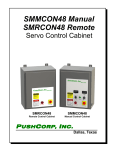
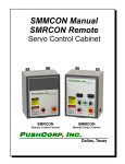
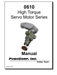
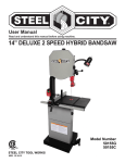
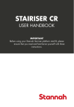
SBS81 Series Servo Belt Stand P USH C ORP, I NC. Dallas, Texas May, 2013 NEVER OPERATE THE SBS81 MANUALLY NEVER OPERATE THE SBS81 WITH PERSONEL IN THE WORKCELL DO NOT USE LUBRICATED AIR. This device requires a dry, non-lubricated 100 psi (6.9 bar) maximum air supply filtered to 5 µm and a 0.3 micron oil mist separator. Non-compliance with these requirements will void the manufacturer’s warranty. (See Section 3.4) All fasteners, mounting holes and pipe threads on this tool are METRIC. All PushCorp, Inc. electrical cables are rated for high twist and flex robotic applications with a minimum cable bending radius specification of 125mm (5 in). Cable damage resulting from failure to abide by this specification will not be covered under warranty. P USHC ORP, I NC. SBS81 Series Manual 1 Table of Contents 1.0 LIMITED WARRANTY...........................................................................................2 2.0 GENERAL OVERVIEW.........................................................................................4 3.0 INSTALLATION.....................................................................................................5 3.1 Mounting the SBS81........................................................................................................................ 5 3.2 Electrical Connections..................................................................................................................... 5 3.4 Pneumatic Connections................................................................................................................... 7 4.0 OPERATION..........................................................................................................9 4.1 Belt Media Installation and Removal................................................................................................9 4.2 Belt Media Tracking....................................................................................................................... 10 4.3 Achieving Desired Force................................................................................................................ 10 4.4 Achieving Desired Belt Media Speed............................................................................................. 10 4.5 Servo Motor Drive Belt Replacement............................................................................................. 11 4.6 Contact Wheel Replacement......................................................................................................... 11 4.7 Contact Wheel Position Feedback................................................................................................. 11 Copyright PushCorp, Inc. 2013. All rights reserved P USHC ORP, I NC. SBS81 Series Manual 2 1.0 Limited Warranty Duration: One year from date of delivery to the original purchaser. Who gives this warranty (warrantor): PushCorp, Inc. Telephone: (972) 840-0208 Corporate Address: P. O. Box 181915 Dallas, Texas 75218 Shipping Address: 3001 W. Kingsley Rd. Garland, Texas 75041 Who receives this warranty (purchaser): The original purchaser (other than for purposes of resale) of the PushCorp, Inc. product What products are covered by this warranty: Any PushCorp, Inc. Adjustable Force Device or Adjustable Force Device accessory supplied or manufactured by the Warrantor. What is covered under this warranty: Defects in material and/or workmanship which occur within the duration of the warranty period. What is NOT covered in this warranty: A. IMPLIED WARRANTIES, INCLUDING THOSE OF MERCHANT-ABILITY AND FITNESS FOR A PARTICULAR PURPOSE ARE LIMITED TO ONE YEAR FROM THE DATE OF ORIGINAL PURCHASE. Some states do not allow limitations on how long an implied warranty lasts, so the above limitations may not apply to you. B. ANY INCIDENTAL, INDIRECT, OR CONSEQUENTIAL LOSS, DAMAGE or EXPENSE THAT MAY RESULT FROM ANY DEFECT, FAILURE, MALFUNCTION OF THE PUSHCORP, INC. PRODUCT. Some states do not allow the exclusion or limitation of incidental or consequential damages so the above limitation or exclusion may not apply to you. C. Any failure that results from an accident, purchaser's abuse, neglect, unauthorized repair or failure to operate the products in accordance with the instructions provided in the owner's manual(s) supplied with the product. Responsibilities of the Warrantor under this warranty: Repair or replace, at Warrantor's option, products or components which have failed within the duration of the warranty period. Copyright PushCorp, Inc. 2013. All rights reserved P USHC ORP, I NC. SBS81 Series Manual 3 Responsibilities of the purchaser under this warranty: A. Deliver or ship the PushCorp, Inc. product or component to PushCorp, Inc. Service Center, Dallas, TX. Freight and insurance costs, if any, must be borne by the purchaser. B. Use reasonable care in the operation and maintenance of the product as described in the owner's manual(s). When warrantor will perform repair or replacement under this warranty: Repair or replacement will be scheduled and serviced according to the normal work flow at the service center, and depending on the availability of replacement parts. Purchasers requiring quicker repair may receive such with payment of a PushCorp, Inc. predetermined expediting fee. This Limited Warranty gives you specific legal rights and you may also have other rights which vary from state to state. Copyright PushCorp, Inc. 2013. All rights reserved P USHC ORP, I NC. SBS81 Series Manual 4 2.0 General Overview The PushCorp SBS81 Series Servo Belt Stand combines passive compliant force control and closed-loop servo motor speed control technology. The SBS81 has been designed from the ground up as a belt stand for robotic finishing with many new and unique features. Accurate force and speed control allows you to achieve unprecedented levels of quality and consistency. The SBS81 enables maximum flexibility for any partin-hand grinding, sanding, buffing or polishing application. Linear compliance with 1.6 inches (40 mm) of travel and excellent access allow a robot to easily manipulate parts over the Belt Media. An important feature of the SBS81 Belt Stand is the high torque servo motor and belt drive. The belt drive system provides a 2:1 increase in torque at the contact wheels for heavy material removal. The force control technology in the SBS81 is based on the PushCorp Passive AFD80 Series Force Devices. This technology has proven itself in thousands of hours of production robotic applications. A basic regulator supplied in the SBS81 Control Box allows the SBS81’s force to be varied from 2 to 100 lbs. (8 to 445 N). This regulator has a coarse adjustment and must be manually set to the desired force output. If the force must vary during the finishing process, then an electrically controlled proportional regulator is required. Very accurate force output requires a precision regulator that operates in a narrow pressure range. The SBS81 has a number of notable features that contributes to ease-of-use, and greater throughput. The Belt Media can be tracked remotely outside the work cell for convenience and user safety. When the Belt Media needs replacing the operator manually releases the tension using a lever mounted right on the unit. A belt tension sensor is provided to notify the user that the Belt Media has not been tensioned. A belt break sensor is also provided to notify the user if the Belt Media should break. These sensors can be used by the customer to program faults to prevent the system from starting should the Belt Media not be tensioned, or to move the robot away, and stop the system should a belt break. These features protect the user and equipment, while also reducing downtime. In most any finishing process, consistency is of paramount importance. For this reason the SBS81 is powered by a high torque servo motor with adjustable speed control that can be varied at any time during the finishing process. The SBS81 has a 5.7 horsepower (4.28 kW) motor that supplies 14.7 lb •ft (20 N•m) of torque and a maximum speed of 3000 RPM at the contact wheels. This provides a range of Belt Media surface speeds from 100 to 11000 SFPM (Surface Feet Per Minute). The SBS81 requires 14 inch (356 mm) diameter Contact Wheels with a width of 2”, 3”, or 4”. The unit is setup to use standard 132 inch long Belt Media. For multi-media finishing applications, the rubber contact wheel can be replaced with Scotchbrite , or cloth wheels. This flexibility allows the SBS81 to perform a wide variety of finishing applications. Copyright PushCorp, Inc. 2013. All rights reserved P USHC ORP, I NC. SBS81 Series Manual 5 3.0 Installation 3.1 Mounting the SBS81 The SBS81 Servo Belt Stand is secured by four (4) fasteners passing through mounting holes located in the Base Plate (See Figure 4). The Base Plate mounting hole locations are shown in Figure 1. The SBS81 must be securely mounted to keep the unit from moving during operation. The unit must be mounted level to achieve the desired force output at the Contact Wheels. A spirit level can be place on the top of the Belt Stand and shims can be inserted under the Base Plate as required. WARNING: Do NOT operate the unit without first mounting it securely. Figure 1. SBS81 Base Plate The SBS81 attaches with four (4) fasteners, 1/2 inch (12 mm) in diameter. fasteners are to be provided by the installer. These 3.2 Electrical Connections The SBS81 requires 208 - 480 VAC 3-Phase 50-60 Hz. power to operate. This should be supplied to the Power Connector on the Control Box. The electrical interface for servo motor control, AFD feedback, and Belt Media tracking is operated through the User Interface Connector. Figure 2 shows a typical manual interface schematic, which Copyright PushCorp, Inc. 2013. All rights reserved P USHC ORP, I NC. SBS81 Series Manual 6 the customer could implement. The unit is supplied with plugs for both the Power Connector and User Interface Connector Figure 2. SBS81 Typical User Interface Schematic The circuit diagram in Figure 2 shows the SBS81 wired for stand-alone panel operation. All circuitry on the SBS81 is designed for 24 VDC control voltages. The switch elements connected to Pins 13, 14, and 15 control the remote belt tracking feature of the unit. The right and left side are defined by viewing the unit from the front facing the Contact Wheels. The selector switch connected to Pin 13, determines which side will be controlled for the belt tracking operation. The push button switches on Pins 14 and 15 turn on the selected belt tracking actuator to track the belt outward and inward respectively. These customer panel mount push buttons may be replaced with relays if remote robot teach pendent operation is desired. The Belt Media/Contact Wheel speed is controlled via a 0 - 10 VDC analog signal applied to Pins 9 and 10. Providing a positive analog voltage will rotate the Contact Wheels in a downward direction when facing the unit from the front. The SBS81 is normally rotated in this direction to direct dust to the floor or into a user supplied dust collection system. The analog input is a true floating differential signal connected directly to the servo amplifier. The circuit shown in Figure 2 is an example of how the Contact Wheel speed may be controlled with a simple panel mount linear potentiometer. If remote robot teach pendent adjustment is desired, the potentiometer would be Copyright PushCorp, Inc. 2013. All rights reserved P USHC ORP, I NC. SBS81 Series Manual 7 replaced with a 0 - 10VDC analog signal from a robot or PLC analog output card connected directly to Pins 9 and 10. WARNING: The differential voltage applied to Pins 9 and 10 should not exceed 10 VDC or damage will occur to the servo amplifier. Terminal 7, shown in Figure 2 provides the servo amplifier enable signal. Connecting Terminal 7 to +24VDC enables the servo amplifier and applies voltage to the servo motor. Removing voltage from terminal 7 disables the amplifier. The “DRIVE OK” output on Terminal 11 should be continuously monitored by the Enduser control system. This signal should be “ON” during normal operation. An “OFF” condition indicates a drive fault. The cause of the fault will be indicated by a flashing code on the servo drive amplifier. OPERATION SHOULD CEASE UNTIL THE FAULT CONDITION IS CORRECTED. The Electrical Control box includes a built-in E-Stop push button switch that, when pressed, immediately removes all electrical power from the motor. If desired, the SBS81 can be connected to an external, dual-channel, E-Stop circuit by connecting to the STO1 and STO2 signal on Terminals 3, 4, 5, and 6 as shown. It is the responsibility of the System Integrator or End-user to follow all applicable electrical codes and OSHA safety standards when wiring the SBS81. This includes the proper and judicious use of fuses, contactors, cut-off switches, lockout switches, and Emergency Stop circuits. PushCorp, Inc. assumes no responsibility or liability for the electrical system design and implementation of the SBS81 in the End-user application. Refer to OSHA rules and regulations, as well as the CE Machinery (IEC 204-1), when designing systems that include motors and drives to ensure that the user is protected. PushCorp will provide answers to any questions regarding the servo drive system and will be responsible for any warranty issues. Copyright PushCorp, Inc. 2013. All rights reserved P USHC ORP, I NC. SBS81 Series Manual 8 3.3 Electrical Control Box The SBS81 Electrical Control Box is designed to be wall mounted outside the robot work area in a relatively clean environment. Figure 4 shows the mounting dimensions of the electrical enclosure. Figure 4. Electrical Control Box Mounting It is the responsibility of the installer to punch holes in the enclosure for conduit and/or cord grips as required for the electrical supply power wiring and low-voltage control signals. 3.4 Pneumatic Connections The SBS81 Belt Stand requires a dry, non-lubricated, 5 micron filtered, 80 to 100 psi (5 to 7 Bar) air supply with a 0.3 micron oil mist separator. Failure to provide supply air to these specifications can degrade performance and will void any warranty repairs concerning pneumatic components. Additionally, a minimum 80 psi (5 Bar) air pressure must be maintained for the device to operate within published specifications. Low air pressure will cause inferior force control performance and not allow the Belt Media to be properly tensioned. The pneumatic supply system should be configured as shown in Figure 3. Figure 3. Pneumatic configuration Copyright PushCorp, Inc. 2013. All rights reserved P USHC ORP, I NC. SBS81 Series Manual 9 WARNING: If water condensation is a problem in your air supply system, an air dryer device is highly recommended. Moisture inside the device will cause premature failure that will not be covered under warranty. The SBS81 Belt Stand maintains a positive air pressure to impede the infiltration of contaminate materials. It is important to provide a continuous compressed air supply to the device at all times if the work environment contains airborne contaminates. If the environment is clean during non-operational periods, the air supply to the device may be shut off. The SBS81 has one pneumatic input, an R 1/8 (Metric) port located on the SBS81 Control Box (Figure 3). This port supplies all the air needed to operated the Belt Stand. Before connecting the supply to the air fitting, open the supply valve to blow out any contaminates which may be in the line. Charge the supply line with compressed air and verify that there are no air leaks and that there is a minimum of 80 psi (5 Bar). If a minimum air pressure of 80 PSI cannot be achieved, then an auxiliary air compressor or booster pump must be installed. Copyright PushCorp, Inc. 2013. All rights reserved P USHC ORP, I NC. SBS81 Series Manual 10 4.0 Operation RIG HT TRAC KING WHEEL BELT TENSION RELEASE LEVERS BELT TENSION PRESSURE G AUG ES BELT TENSION PRESSURE ADJ USTMENT KNOBS BELT MEDIA LEFT TRAC KING WHEEL C ONTAC T WHEELS POWER C ONNEC TOR USER INTERFAC E C ONNEC TOR BASE PLATE Figure 4. SBS81 Belt Stand 4.1 Belt Media Installation and Removal The SBS81 uses 2”, 3”, or 4” wide by 132” long Belt Media. To install new Belt Media, verify the servo motor and robot are disabled, then position the Belt Media Tension Release Lever towards the Contact Wheels of the SBS81, which releases the tension on the Belt Media. Install new Belt Media over the Contact Wheel and the Tracking Wheel as shown in Figure 4. Then tension the Belt Media by positioning the Belt Tension Release Lever to its rearward position. To remove the Belt Media reverse the previous steps. Proper tension is required for each Belt Media width and type. The Belt Tension Pressure Adjustment Knobs are located at the rear of the machine, see Figure 4. The Belt Media tension should never be adjusted while the machine is operating. Belt Media Tension Pressure Gauges are located on the top of the machine to allow accurate setting of the pressure. The following chart is only a guideline for proper Belt Media tension pressures. The user is responsible for contacting the Belt Media manufacturer for the correct Belt Media tension. Belt Width 2” 3” 4” Belt Media Tension Pressure 0.4 MPa 0.5 MPa 0.6 MPa Belt Media Tension 57 lbs. (254 N) 71 lbs. (316 N) 85 lbs. (380 N) .1 MPa Belt Media Pressure Gauge = 14.2 lbs. (63.1 N) Belt Media Tension Copyright PushCorp, Inc. 2013. All rights reserved P USHC ORP, I NC. SBS81 Series Manual 11 4.2 Belt Media Tracking The SBS81 uses electromechanical linear actuators to automatically adjust and hold the tracking of the Belt Media on the Contact Wheels. The Belt Media cannot be tracked manually. The user moves the Tracking Wheel by automatically extending or retracting the Linear Actuator. Moving the Linear Actuator will cause the Belt Media to track from side to side on the Contact Wheel. The Belt Media can only be tracked while the Contact Wheels are rotating. The Contact Wheels should be rotated at approximately 500 rpm. Attempting to track the Belt Media at high rpm’s will cause the belt to move too quickly. The user must select which Tracking Wheel is to be adjusted. The Linear Actuators cannot be back-driven and will hold their position. 4.3 Achieving Desired Force The SBS81 uses a passive 80 Series AFD to supply a compliant force from 2 to 100 lbs. (8 to 445 N). The passive force device requires the user to provide regulated air pressure to achieve a desired force output at the Contact Wheels. Use the following equations to determine the pressure required to achieve the desired output force: Fa = (1.4 × Ps ) English units Fam = (89 × Ps ) Metric units Where: Fa = Net applied force (lbs.) at Contact Wheels Fam = Net applied force (N) at Contact Wheels Ps = Supply pressure (psi or bar) PushCorp has included a manual regulator in the SBS81 Control Box to allow for quick set-up. A manually adjustable pressure regulator may be sufficient, but if remote operation of the force output is needed, then an electrically controlled proportional air regulator will be required. The accuracy of the force output is directly related to the precision and quality of the pressure regulator. For the most precise force output a regulator that operates in a limited range (i.e., 0-15 psi) is required. 4.4 Achieving Desired Belt Media Speed The Belt Media speed and Output Shaft rpm is controlled via a +/- 10 VDC analog signal applied to Pins 4 and 5 of the User Interface Connector. The user must scale the command voltage to the servo motor amplifier from 0 to 10 Volts, which equates to a Belt Media speed of 0 to 11000 SFPM (Surface Feet Per Minute). The user is responsible for determining the maximum speed for their Belt Media. The SBS81 is factory limited to operate at a maximum Output Shaft rotational speed of 3000 rpm (11000 SFPM Belt Media speed). Figure 2 shows a simple circuit using a linear potentiometer to control Belt Media speed, however most installations will require a remote voltage command to vary the Belt Media speed and control the acceleration/deceleration of the unit. Copyright PushCorp, Inc. 2013. All rights reserved P USHC ORP, I NC. SBS81 Series Manual 12 4.5 Servo Motor Drive Belt Replacement The SBS81 uses a 2:1 reduction timing belt drive to transfer power from the Servo Motor to the Contact Wheels. This drive incorporates a high-strength Gates Poly Chain GT2 belt, PushCorp Part No. PAR01889-1. Should this Drive Belt ever require replacement, contact PushCorp for the proper procedure. 4.6 Contact Wheel Replacement Contact Wheels are not provided with the SBS81, as the user must determine the proper style and hardness for their specific application. The 14” diameter Contact Wheels are easily installed or replaced on the SBS81. They are available in different widths (2”, 3”, or 4”), durometers (hardness), and surface types (plain or serrated). Using different width Contact Wheels on the SBS81 does not require any modifications to the unit. Contact Wheels should be ordered directly from the manufacturer, Contact Rubber Corp., 8635 198th Avenue, Bristol, WI, 53104, Tel: 262-857-2361, Fax: 262857-9483. The SBS81 uses C-134 type Contact Wheels. There are four (4) M10x1.5 Flat Head Socket Screws on the Contact Wheel hub that must be removed to change the Contact Wheel. After removing the screws the hub will split allowing the Contact Wheel to be easily removed. Install a Contact Wheel on the hub and replace the removed hub and the four (4) screws. Tighten the screws to 30 ft.-lbs. (40 N·m). 4.7 Contact Wheel Position Feedback The SBS81 comes equipped with an internal potentiometer that provides a voltage signal based on the linear position of the Contact Wheels. The voltage signal is at a minimum value when the Contact Wheels are pushed back against the rubber stops, and a maximum value when the Contact Wheels are pulled forward against the rubber stops. The total linear compliant stroke is 1.6 in. (40 mm). The linear position signal must be calibrated for each installation. User calibration is easily accomplished using the following steps. 1. Turn off the supply air to the SBS81 2. Move the Contact Wheels to the full rearward (negative) position. 3. Read the voltage signal on Pin 12 of the User Interface Connector. Record this voltage for future reference. This will be referred to as V neg. 4. Move the Contact Wheels to the full forward (positive) position. 5. Read the voltage signal on Pin 12 of the User Interface Connector. Record this voltage for future reference. This will be referred to as V pos. Copyright PushCorp, Inc. 2013. All rights reserved P USHC ORP, I NC. SBS81 Series Manual 13 6. The position of the Contact Wheels can now be determined by measuring the current voltage (Vm) on Pin 12 of the User Interface Connector, and inserting the value into the following equation: Vm −Vneg ( English units ) p = 1.6 in. × V pos − V neg Vm − Vneg ( Metric units ) p = 40 mm × V pos − V neg Where, p = Contact Wheel Position (in., mm) Vm = Voltage measured on PIN 12 (V) Vneg = Calibrated voltage at fully negative Carriage position (V), ( 0 inch, 0 mm) Vpos= Calibrated voltage at fully positive Carriage position (V), ( 1.6 inch, 40 mm) 5.0 Technical Specifications Maximum Applied Force: 100 lbs. (445N) Contact Wheels: 2”-4” Widths, 14” Dia Abrasive Belt Media: 2”-4” Widths, 132” Length Weight: 450 lbs. (204 kg) Force Scale Factor: 1.4 lbs/psi (890 N/MPa) Compliant Stroke: 1.6 in. (40 mm) Supply air: Non-lubricated, Dry, 5µm Filtered, 100 psi (0.7 MPa) Max. Supply Voltage: 240 VAC, 3-Phase Max. Cont. Current: 30 Amps Max. Peak Current: 60 Amps (2 Seconds) Specifications subject to change without notice. Fastener Tightening Torque Specs Torque Fastener Size Minimum Depth in.-lbs. ft.-lbs. N·m in. mm M4 x .7 50 4.2 5.6 0.17 4.3 M5 x .8 85 7.1 9.6 0.21 5.3 M6 x 1 140 11.7 15.8 0.25 6.3 M8 x 1.25 348 29.0 39.3 0.33 8.4 M10 x 1.5 600 50.0 67.8 0.41 10.5 Copyright PushCorp, Inc. 2013. All rights reserved