1
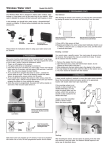
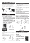
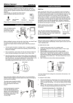
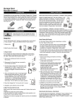
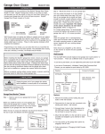
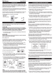
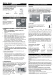
Temperature Sensor
Model TS-101A
1. INTRODUCTION
2. PROGRAMMING (CONT)
The Temperature Sensor is designed to monitor the temperature of a
specific area, whether that is the indoor temperature or outdoor
temperature. It works in conjunction with the AAA+TM Control Panel, as
well as other Skylink’s alarm system such as SC-001 or AD-433S etc.
When the actual temperature exceeds the preset limit, the control panel
will either alert you or alarm will be triggered.
Compatibility Jumper
Refer to the following table to setup the sensor to work with different
Skylink’s Security System or Emergency Dialer. To select, open the back
cover you will see a jumper connector for “J2” as shown below. Use a
paper clip to remove the jumper connector.
Models
In this package, you should find the temperature sensor, 2 lithium batteries,
an external measuring probe for measuring outdoor temperature and
mounting accessories.
2 pcs
Temperature
3.5 x 20 screws
Sensor
(Batteries inside)
Jumper J2 setting
AM-001, ML-001,
AD-105
Keep the connector in
default post
External
measuring
probe
SC-001, AA-433,
AD-433S, MS-2001,
ED-100
External
dry contact cable
Reposition
connector to 2 posts
Please follow the instructions below to set up the temperature sensor.
You have now programmed the temperature sensor and you can
mount the sensor to the desired location.
2. PROGRAMMING
There are several things you need to program:
1) Clock
2) Upper temperature limit
3) Lower temperature limit
4) Set the temperature unit (Fahrenheit / Celsius)
5) Compatibility jumper (J2)
3. LEARN SENSOR TO AAA+TM CONTROL PANEL
Clock
The current time will be displayed when the “HOUR” or “MIN” button is
pressed.
To set the hour:
1. Press and hold the “HOUR” button.
2. While holding on to the “HOUR” button, press “UP” or “DOWN” to
select the hour.
3. Release all buttons after setting the hour.
In order for the sensor to communicate with the control panel properly,
the sensor must be programmed to the control panel. Follow the brief
instructions below or refer to the detail instructions from the AAA+TM
User’s Instructions to program the sensor to the control panel. Before
proceeding, please remove the battery isolator from the sensor.
Step
Keys
[PROG]
[MPIN]
2
[3]
Select learn
sensor
programming
3
[0] to [9]
Select sensor
location
4
Activate the Activate sensor Once the sensor
sensor by
is activated, the
pressing the
signal will be transred “Panic”
mitted to the Conbutton on the
trol Panel which
temperature
will be stored.
sensor.
Lower Temperature Limit
When the actual temperature is below the lower temperature limit, the
temperature sensor will send a signal to the control panel.
To set the lower temperature limit:
1. Press and hold the “LO” button.
2. While holding on to the “LO” button, press “UP” or “DOWN” to select
the lower temperature limit.
3. Release all buttons after setting the lower temperature limit.
Set the temperature unit (Fahrenheit / Celsius)
The temperature sensor can operate and
display temperature in Fahrenheit or
Celsius. To select the desire unit, open
the back cover you will see a jumper
connector for “C/F” as shown below.
To select Fahrenheit, place a jumper on
this “C/F” connector. To select Celsius,
remove the jumper from this connector.
Refer to the diagram below to
select the sensor
location, which
includes the zone
and sensor
number.
Note
3 beeps for valid
password. 1 long
beep for invalid
password.
After [3] is entered,
some zone LEDs will
flash once, or twice,
some will be off. The
zone LEDs represent
whether that zone is
already occupied by
another sensor.
**See Table A below.
After you have
selected the zone,
that zone LED will
be on.
You will hear [Zone X
Sensor Y Accepted],
where X and Y are
the zone and sensor
numbers you have
selected.
This row :
Buttons for
Sensor 1
Zone LED :
Flash once
Remove
back cover
This row :
Buttons for
Sensor 2
Zone LED :
Flash twice
SENSOR 1
Fahrenheit
Description
1
To set the minute:
1. Press and hold the “MIN” button.
2. While holding on to the “MIN” button, press “UP” or “DOWN” to
select the minute.
3. Release all buttons after setting the minute.
Upper Temperature Limit
When the actual temperature is above the upper temperature limit, the
temperature sensor will send a signal to the control panel.
To set the upper temperature limit:
1. Press and hold the “HI” button.
2. While holding on to the “HI” button, press “UP” or “DOWN” to select
the upper temperature limit.
3. Release all buttons after setting the upper temperature limit.
Function
Enter Program- Enter master
password to
ming mode
programming
mode
Celsius
Note: The temperature sensor can monitor the temperature within this
range: 157°F (69°C) to -3°F(-19°C).
SENSOR 2
Zone 1
Button [1]
Button [6]
Zone 2
Button [2]
Button [7]
Zone 3
Button [3]
Button [8]
Zone 4
Button [4]
Button [9]
Zone 5
Button [5]
Button [0]
Note:
Each location is allowed to learn one
sensor only. Learning a sensor to a
location will clear the memory of the
sensor previously learnt.
3. LEARN SENSOR TO AAA+TM CONTROL PANEL (CONT)
7. SENSOR FAILURE OR LOW BATTERY (CONT)
-
(Only available for AAA+TM)
DESCRIPTION
Sensor Low Battery
Off
Zone is not occupied by any sensor
Flashes once
This zone is occupied by sensor 1.
Two CR-2032 lithium batteries are used to operate the temperature sensor.
When the sensor is in low battery condition, the low battery LED indicator
will flash. Temperature sensor will also send a wireless low battery signal
to the AAA+TM Control Panel.
ZONE LED
Flashes twice
This zone is occupied by sensor 2.
Flashes once, then twice
This zone is occupied by sensors 1 and 2.
** Table A: Zone LED status for learning sensors.
4. LEARN SENSOR TO SC-001, AA-433 AND AD-433S
To program the temperature sensor to other Skylink’s receivers, such as
SC-001, AA-433, AD-433S etc, please follow the instructions below:
1) Activate the programming mode of your Skylink’s receiver (refer to the
owner’s instructions of your Skylink’s receiver)
2) To transmit the signal from the temperature sensor, press the red button
on the temperature sensor. The red button is for programming
purpose only.
3) Follow the rest of the instructions from the Skylink’s receiver to complete
the programming procedure.
5. INSTALLATION
The temperature sensor should be mounted onto the wall by 2 screws.
Follow the procedures below:
1. Use a template to mark the location for the 2 screws correctly.
2. Tighten the screws onto the wall half way.
3. Hang the temperature sensor onto the 2 screws.
Note: The temperature sensor is not designed to be used outdoor, it must be
installed indoor. To monitor outdoor temperature, an external measuring
probe can be used, while the temperature sensor is installed indoor.
6. OPERATION
The temperature sensor must be enabled in order to monitor the temperature
and communicate with the control panel. You may enable the upper temperature limit only, or lower temperature limit only, or both.
To enable the upper or lower temperature limit, simply press “HI” or “LO”. If the
display shows “HI”, that means the upper temperature limit is enabled. If the
display shows “LO”, that means the lower temperature limit is enabled. If the
display shows both “HI” and “LO”, that means both upper and lower temperature limits are enabled. To disable the temperature limits, simply press the
same button again, until the “HI” or “LO” doesn’t show up on the display.
External Temperature
If you would like to monitor the external temperature (i.e. outdoor temperature), you may use the external measuring probe. Plug in the external
testing probe as show on the back of the sensor. Ensure to select the
“EXT” on the front panel. If no external measuring probe is plugged in,
but “EXT” is selected, the display will not show any temperature.
External Dry Contact (Normal Open)
You may connect the temperature sensor to other
devices by the N/O dry contact. Simply plug in the
cable into the socket on the back of the sensor as
shown. Connect the other end of the cable to the
device that you would like to connect to. When the
temperature is above or below the preset limits,
the contact will be closed momentary therefore
activating the connected device.
When you see the low battery indication, replace
the batteries following the procedures below:
1) Remove the screw on the back of the
temperature sensor as shown.
2) Rotate the battery compartment, the
batteries can be removed.
3) Place the new batteries into the
compartment, pay attention on the
polarity, as indicated on the diagram.
4) Tighten the screw.
8. FCC
This device complies with Part 15 of the FCC Rules. Operation is subject to the
following two conditions: (1) This device may not cause harmful interference, and
(2) This device must accept any interference received, including interference that
may cause undesired operation.
WARNING:
Changes or modifications to this unit not expressly approved by the party
responsible for compliance could void the user’s authority to operate the equipment.
NOTE:
This equipment has been tested and found to comply with the limits for a Class B
digital device, pursuant to Part 15 of the FCC Rules. These limits are designed to
provide reasonable protection against harmful interference in a residential installation.
This equipment generates, uses and can radiate radio frequency energy and, if not
installed and used in accordance with the instructions, may cause harmful interference to radio communications.
However, there is no guarantee that interference will not occur in a particular
installation. If this equipment dose cause harmful interference to radio or television
reception, which can be determined by turning the equipment off and on, the user is
encouraged to try to correct the interference by one or more of the following measures:
- Reorient or relocate the receiving antenna.
- Increase the separation between the equipment and receiver.
- Connect the equipment into an outlet on a circuit different from that to which the
receiver is connected.
- Consult the dealer or an experienced radio/TV technician for help.
9. CE
Declaration of Conformity
This equipment conforms to the essential requirement of the Directive (1999/5/EC)
of the European Parliament and of the Council.
10. WARRANTY
External Dry Contact
If, within one year from date of purchase, this product should become defective
(except battery), due to faulty workmanship or materials, it will be repaired or
replaced, without charge. Proof of purchase and a Return Authorization are required.
External
Temperature
The maximum ratings of the N/O relay contact is 2A / 24V DC, therefore do
not connect an external device which exceeds this rating. The relay contact
is not designed for AC connection, DO NOT CONNECT AC DEVICE TO THIS
N/O CONTACT.
11. CUSTOMER SERVICE
If you would like to order Skylink’s products or have difficulty getting them to
work or download latest information and user manual, please :
1. visit our FAQ section at www.skylinkhome.com, or
2. email us at [email protected], or
3. call our toll free at 1-800-304-1187 from Monday to Friday, 9 am to 5 pm EST.
Fax (800) 286-1320
7. SENSOR FAILURE OR LOW BATTERY
Sensor Failure
-
(Only avaliable for AAA+TM)
The control panel constantly monitors its sensors, if the control panel fails
to communicate with any sensors, it will notify the user by:
1. The zone LED of the failed sensor will be on steadily;
2. Voice announcement “zone X sensor Y failure” will be played.
When sensor failure occurs, try the following:
1. Check if the sensor is located at where it should be, and whether there
is any physical damage to the sensor.
2. If the failed sensor is not physically damaged, try to activate the sensor
and see if the control panel reacts to such activation.
3. If not, try to remove the sensor from its location, and bring it closer to
control panel and activate the sensor. It is possible that the sensor is
installed too far from the control panel and it cannot establish a steady
communication with the control panel. If this is the case, please install
the sensor closer to the control panel.
CUSTOMER SERVICE
17 Sheard Avenue, Brampton, Ontario, Canada L6Y 1J3
Email:[email protected]
http://www.skylinkhome.com
P/N. 101Z468-002
US Patent. 6243000B1
©2008 SKYLINK GROUP