1
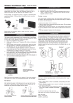
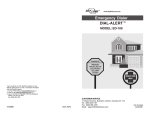
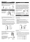
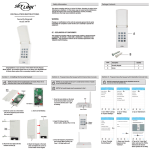
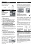
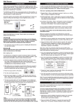
Introduction
The Audio Sensor (AS-433) is designed to detect
sound frequency from the siren of your existing
security system. Once the siren goes off, the Audio
Sensor will be activated and therefore triggers the
emergency dialer (AD-433S) by sending radio frequency (RF) signal or through hardwire connection. The Audio Sensor is designed to recognize
only the siren from your existing security system,
therefore it will not pick up any background noise
if the sensor is installed properly.
The sensor can also work in conjunction with all of
the Skylink receivers that incorporate the Rolling
Code Technology (Security Control Panel SC001, Emergency Dialer AD-1010, Audio Alarm
AA-433, and Silent Alarm SW-433).
Installing the Audio Sensor
Set up the Audio Sensor
1. Place the Audio Sensor as close as possible to the siren or alarm
unit of your existing security system. This distance between the
sensor and the siren should be less than 6 inches.
Note: Selecting the place to locate the AS-433 is very critical, since
this will affect the operation and performance of the sensor. You
should avoid placing the Audio Sensor near any unwanted sound
sources (such as TV, stereo) to eliminate false trigger by background noise.
1. Plug in the AC adapter and ins ert the wire to the “DC 9V” jack. If
there is no electrical outlet nearby the audio sensor, you may use the
9V alkaline battery as the main power source. If both power suppliers
are connected, the 9V adapter will be the main power, 9V alkaline
battery will become the backup power supply.
2. Turn on the unit to test mode (by sliding the ON/OFF/TEST switch
to “TEST”). The red light indicator will flash once you turn on the unit.
3. Allow 15 seconds for the sensor to warm up.
4. Rotate the “Volume” to “LO”.
5. If the light indicator on the AS-433 turns on as the siren is sounding,
that means it can detect the sound from the siren and the installat ion
of the AS-433 is now completed.
6. If the red light indicator does not turn on, which means the sensor
cannot hear the siren. So you need to increase the volume setting
by slightly rotating the “Volume” switch.
7. Activate the siren again and see if the audio sensor can hear the
siren. If the red light indicator does not turn on, repeat step 6 until
the red light indicator turns on.
2. Plug in the DC adapter cord to the DC jack on the Audio Sensor,
and plug in the other end to an electrical outlet. If there is no electrical outlet nearby, the Audio Sensor can be operated by 9V battery
as well. Please refer to External Jack - External power supply for
more detail information.
3. Apply the Velcro to the back of the sensor as well as the wall.
4. Locate the Audio Sensor AS-433 and make sure it is secure.
Caution: Please make sure the Audio Sensor can only be triggered
by the real alarm siren. Some of the alarm systems will emit other
sounds under different situations such as entry delay deeps (this is
to warn the user the alarm has been triggered, user has to enter the
password within a short period of time otherwise the alarm will go
off). Please make sure the Audio Sensor can only detect the intented
alarm sound pattern. Since the intented alarm is usually a lot louder
than other sound patterns. If the AS-433 c an detect other sound patterns from the alarm systems, please adjust the "Volume" so that it
can only detect the intented alarm.
Program the Audio Sensor to the Security Control
Panel (SC-001)
PANIC BUTTON
Set up the Audio Sensor
VOLUME
LO / HI
DELAY
LO / HI
MIC
8. You should test the sensor several times in order to ensure it can
hear the siren.
Caution: You should keep the “Volume” setting as low as possible
in order to eliminate false trigger by any background noise.
DC 9V
TEST / ON
EXT. JACK
1. Set the ON/OFF/TEST switch on the side of the Audio Sensor to “ON
and
allow 15 seconds for the unit to warm up.
2. Enter the current MPIN (Master Personal Identification Number) on the
SC001.
3. Press [B].
4. Press the number key to identify which zone to add the Alarm Sensor to, zone
[1, 2, 3, 4]. It is not recommended to program this sensor to zone 1 or 2
because these zones are intended for Delay Mode.
5. The zone light(s) will flash for eight seconds.
*
6. While the zone light(s) are flashing, press [ ]. Now both the green and
red lights flash for 30 seconds.
7. While the zone lights are flashing, activate the Audio Sensor by pressing
the Panic button on the AS-433. You will hear a long beep from the SC001, the zone light will stop flashing and the Audio Sensor will now communicate to that zone.
1. Set the ON/OFF/TEST switch on the side
of the Audio Sensor to “ON” and allow 15
seconds for the unit to warm up.
2. Press [L], [5] on the keypad of the dialer
when in clock mode, the display will show
“L5 IdcodE”.
3. Activate the Audio Sensor by pressing
the Panic button on the AS-433.
When the red light indicator turns on, that
means it is transmitting the signal to the
dialer. Once the dialer has learned the signal, the display will return to clock mode.
Program the Audio Sensor
to the Audio Alarm (AA-433)
1. Set the switch on the side of the
Audio Sensor to “ON”. Wait 15
seconds to warm up.
2. With only the “ON” light lit on
the Audio Alarm, press and hold
the learn button located on the
bottom of the Audio Alarm.
3. While pressing down on the
learn button, activate the Audio
Sensor by pressing the Panic
button on the AS-433.
4. If a connection has been made,
the Audio Alarm will stop beeping
and make a continuous tone
until the black learn button
on the Audio Alarm is released.
Battery Maintenance
When the voltage of the 9V battery drops to a certain level, the audio
sen-sor will notify you by flashing the red light indicator every 8
seconds. This indicates the 9V battery needs to be replaced. Note:
When the 9V adapter
is connected to the AS-433, the low battery indication will be disabled.
Normal Operation
External Jack
Once you have installed your audio sensor properly,
you should not change the setting since it will affect
the operation of the sensor, and therefore may cause
false alarm or malfunction. In order to activate the
audio sensor, it has to detect the siren or similar
sound source for a fixed amount of time, either 4
seconds or 8 seconds. This timing can be set by
adjusting the Delay Time setting. When the Delay
time is set to “LO”, the AS-433 has to detect the siren
for approx. 4 seconds in order for it to be triggered.
When the Delay time is set to “HI”, this timing will be
changed to 8 seconds. This will eliminate the chance
of false alarm. Once the audio sensor is activated,
it will send a signal to trigger the emergency dialer
(AD-433S). The dialer will then start dialing out all the
preset phone numbers and ask for help.
Warranty
If, within one year from
date
of purchase, this product
should become defective
(except battery), due to
faulty workmanship or
To replace the battery:
1. Turn off the audio sensor and disconnect the AC adapt er from the sen- materials, it will be repaired
or replaced, without charge.
sor (if the adapter is connected).
Proof of purchase is
Caution: If the N/C hardwire connection is made, disconnecting the
power or turning off the Audio Sensor will trigger the dialer. Therefore, required.
before replacing the battery, or turning off the power, please disable
the dialer.
2. Pry off the battery cover and remove the old
battery from the battery compartment.
3. Connect the new 9V alkaline battery to the connector wire and place the battery inside the
battery compartment.
4. Slide the battery cover back on.
5. Turn the Audio Sensor to “ON” mode.
FCC
The Remote Control is approved
by the FCC and it complies with
Part 15 of the FCC Rules. Its
operation is subject to the
following two conditions :
1. This device may not cause
harmful interference.
2. This device must accept
any interference that may
cause undesired operation.
WARNING:
Changes or modifications to
this unit not expressly approved
by the party responsible of
compliancecould void the user’s
authority to operate the
equipment.
Normally Closed (N/C) Relay Dry Contact
The audio sensor can work with the dialer through radio frequency (wireless) or Normally Closed Contact (wire connection). You may insert one
end of the wire (included) to the audio sensor and connect the other end
of the wire to the N/C contact of the emergency dialer (please refer to the
user manual of the dialer for more detail information). If the sensor is
activated, it will trigger the dialer through the wire connection.
Caution: Once the hardwire connection is established between the dialer
and the Audio Sensor, the Audio Sensor will be activated if the connection
is broken or if the Audio Sensor is turned off.
External power supply – DC 9V
The Audio Sensor can be powered by either 9V alkaline battery or external
AC power adapter. When the AC adapter is plugged in, the 9V alkaline
battery works as a back up battery. In case of a power failure, the audio
sensor can still operate normally. On the other hand, you can use the 9V
alkaline battery as the primary power source as well if 9V DC is not connected.
NOTE
If you would like to order Skylink’s
product or have difficulty getting
your Skylink’s product to work,
please :
1. visit our website FAQ at
www.skylinkhome.com , or
2. email us at
[email protected]
3. call our toll free at
1-800-304-1187 from Monday
to Friday, 9 am to 5 pm EST.
Fax +800 286-1320
Skylink will not be held
liable or responsible for
any misuse or application
of this product other than
for its intended use.
CUSTOMER SERVICE
17 Sheard Avenue, Brampton,
Ontario, Canada L6Y 1J3
Email:[email protected]
http://www.skylinkhome.com
P/N. 101A342 Rev.0
US Patent 6243000B1
©2004 SKYLINK GROUP
®
® are registered trademarks of their
respective corporations
Program the Audio Sensor to
the Emergency Dialer (AD-433S)
AUDIO SENSOR
USER'S INSTRUCTIONS
(Model AS-433)