1
United States Patent [19]
[11] Patent Number:
Sheahan et al.
[45]
[54]
LOCAL CONTROL APPARATUS FOR
4,088,983
CENTRAL STATION ALARM SYSTEM
2,133,723
[75] Inventors: Robert F. Sheahan, Staten Island,
13:3
1g;
[21] App 1' No': 473’794
Primary Examz'ner—-Donnie L. Crosland
Mar, 10, 1983
Attorney, Agent, or Firm—-Robert R. Jackson; Charles B.
Smith
Related U.S. Application Data
[57]
Division Of Sef- NO- 409,181, Aug‘ 18, 19823
ABSTRAC1‘
In a central station alarm system the alarm sensors asso
ciated with a particular subscriber’s premises are moni
"""""""""""""""""""
'
'
4:206:44‘) 6/1980
Company, Jersey City, NJ.
[62]
Jul. 10, 1984
5/1978 Crandall ............................ .. 340/505
rig/$5153
[73] Assignee: American District Telegraph
Filed;
Date of Patent:
4:l61:721 7/1979
N.Y.; David S. Terrett, Lincroft, NJ.
' [22]
4,459,582
69
tored by a local control unit associated with those prem
340/5151 340/5183 340/527:
ises and controllable by the subscriber. The local con
340’/528_ 3407333‘ 3407825 O6_ 3’40/825 1f
’
trol unit automatically reminds the subscriber when he
[58] F. Id fsearch
340/8‘25 at 179/5'R’
34O/5'39’ 502411
18348517 51
527 528’ 531 532’
change his expected closing time. The local control unit
536_538’ 635’ 636’ 693’ 660L663’ 541’ 577’ 584’
587 58’8 82’5 05’ 825’06 333 ’825 3’l 82’5 32’
may also perform various other functions such as auto
matically cutting off power to low priority alarm sen
’
’
’
' ’ 825‘1 ’825 1’3_ 17'9/5 R
' _
[56]
'
’
sors during a prolonged power failure, automatically
’
cancelling any audible alarm indication silence com
References Cited
mands when there are no alarms to silence, and auto
matically forming a bridge connection between the
U.S. PATENT DOCUMENTS
remote ends of two communication circuits when there
3,408,642 10/1968 Palladino ........................... .. 340/543
3,544,987 12/1970
McMann ..... ..
3,881,171
4/1975 Moorrnan ..
3,978,478
8/1976
Schm1tz
is a break in either circuit.
.. 340/539
.. 340/542
. r. . . . . . .
. . . . ..
4,048,620 9/1977 Crandall
4,048,621
is supposed to close the premises and turn on the sys
tem. The local control unit allows the subscriber to
9 Claims, 8 Drawing Figures
340/506
340/825.45
_
_
Micro?che Appendix Included
9/1977 Conklin ........................ .. 340/825.45
(2 Micro?che, 182 Pages)
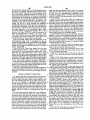
/02'
8
l4
f6
'
W
W
m"
mu; cawmoz. umr
7/2j
/”6)
/”6
CENTRAL __¥ S_ comma/x4102
STAT/0N
mg
L ED
o/sPuy
SEVEN
55:52:,
7/6
114,
MODULE
xzyamgl saw/a6?
,w/
“Min.
“I086
29
63
/5
a
w ‘___
U.S. Patent
Jul. 10, 1984
Sheet 1 of8
WQ
@Q
4,459,582
US. Patent
Jul. 10, 1984
Sheet 2 of 8
4,459,582
SmoWulQ.‘Mv Uo
MS
RNr
‘.@MN3
HMTQNwmw“It
%mHim{mm
/‘WNW. .
NE
ws
5%
M
,lom.
_M@Q
wmég18%
t“4
3,
19assan\2*N»f 3
US“ Patent
Jul. 10, 1984
Sheet 3 of8
9AM
\?wwm
SQM ,
wmm,NNm.
Nmm,WWW,.
?lmUwih.“
4,459,582
US. Pamm
Jul. 10, 1984
Sheet 4 of8
49459?m
U.S. Patent
Jul. 10, 1984
Sheet 5 of8
4,459,582
+at
.in,bFu.
U.S. Patent
Jul. 10, 1984
Sheet 6 01H;v
4,459,582
U.S. Patent
Jul. 10, 1984
Sheet 8 of 8
4,459,582
4,459,582
1
2
It is therefore an object of this invention to provide a
local control unit which eliminates the need for the
subscriber to call the central station whenever he
LOCAL CONTROL APPARATUS FOR CENTRAL
STATION ALARM SYSTEM
wishes to change his‘closing time.
CROSS-REFERENCE TO RELATED
APPLICATION
5
This is a division of application Ser. No. 409,181 ?led
Aug. 18, 1982.
.
alarm sensors, it is desirable to conserve battery power
to operate the ?re‘alarm sensors as long as possible
REFERENCE TO MICROFICHE APPENDIX
A micro?che appendix, comprising 2 micro?che hav
'during an AC power failure.
It is therefore another object of this invention to
ing a total number of l82'frames, is a part of this speci?
cation.
‘Local control unit apparatus frequently includes a
battery ‘to supply power in the event that the primary
alternating current (“AC”) power supply fails or is
interrupted. If the system has both security and ?re
'
provide a local control unit which automatically oper
.
ates to cut off power to non-?re alarm sensors during a
BACKGROUND OF THE INVENTION
This invention relates to central station alarm sys
tems, and more particularly'to local control apparatus
prolonged AC power failure or when remaining battery
power is low in order to conserve battery power for the
longest possible continued operation of the ?re alarm
sensors.
which monitors a plurality of alarm sensors and trans
‘Local control unit apparatus also desirably includes
mits selected alarm signals to a central station.
20 means for allowing an authorized operator of the local
The trend in central station alarm systems is toward
control unit to silence audible security and ?re alarm
the use of more powerful and versatile local control
indications. However, the danger exists when this capa
units. The local control unit in suchsystems is typically
bility is provided that, ‘once activated, the silencing
located on the subscriber’s premises and is connected to
mechanism will be inadvertently left activated too long
various alarm sensors (e.g., smokev detectors,‘ heat sen
and prevent audible indications of a new security or ?re
sors, motion sensors, entry detectors on doors and win
alarm indication.
dows, water ?ow detectors, etc.) distributed through
out the protected premises. The local control unit moni
tors signals from the alarm‘ sensors and transmits appro
priate alarm signals to a remotely located central'sta- ‘
tion. Operators at the central station interpret the alarm
signals received at the central station and dispatch ser
vices (e. g., police, ?re, or maintenance services an‘dtl‘ie
like) to the subscriber’s premises on the basis of the
received alarm signals.
‘
'
i “
"
More sophisticated local control'units are desirable
for many reasons. A more sophisticated local control
unit allows more functions to be controlled ‘locally,
‘
‘
i
It is therefore yet another object of this invention to
provide a local control unit which automatically over
rides the silence mechanism when any new alarm condi
tion is detected and which automatically deactivates the
silence mechanism entirely when all alarm conditions
have been corrected.
Alarm systems having av plurality of distributed alarm
monitoring devices typically include two or more com
35
munication circuits extending from the control cir
Icuitry. ‘The alarm monitoring devices are distributed
along these communication circuits. If a break occurs in
.a communication circuit, it becomes impossible to re
thereby reducing the amount ‘of information “which
ceive alarms from the alarm monitoring devices beyond
must be transmitted to the central station. This increases 140 the break.
'
'
‘
the ef?ciency and lowers the operating cost of the cen
It is therefore still another object of this invention to
tral station because the central station operators have
provide a distributed alarm system in which an alternate
less information to deal with; A more sophisticated
local control unit also enhances the level of protection
afforded by the system because it provides better moni
circuit can be established when needed for communica
tion with alarm monitoring devices beyond a break in a
45
communication circuit.
toring of the alarm sensors and is better able to distin
SUMMARY OF THE INVENTION
guish true alarm conditions from false alarm'ycon‘ditions.
This greatly reduces the transmission of false alarms to
These and other‘objects of the invention are accom
the central station. A more sophisticated local control
plished in accordance with the invention by providing a
unit also allows the subscriber to have much greater 50 local control unit associated with the protected prem
control over his installation without needing to interact
ises, the local ‘control: unit comprising ?rst means for
with the central station personnel. Other advantages of
detecting opening of the protected premises by an au—
advanced local control units for central station alarm
thorized operator, second means for detecting closing
systems are well known to those skilled in the art.
of the protected premises by an authorized operator,
One of the operating dif?culties in many central sta
third means responsive to the ?rst and second means for
tion alarm systems has been that subscribers frequently
transmitting “an ‘alarm signal to a central station if the
wish to change the time at the end of the day at which
they intend to close their premises. In many systems the
subscriber must telephone the central station to report a
change in closing time so that the central station opera v60
‘second means does not detect closing of the protected
premises within a ?rst predetermined time interval after
the ?rst ‘means detects opening of the protected prem
tors will know how to interpret signals received before
and after that time. This restricts the subscriber and
creates a large volume of telephone traf?c forthe cen
tral station. In addition, should the subscriber fail to
contact the central station, operators at the central sta
tion must spend a large amount of time to contact the
ises, fourth means responsive to the second and third
means for producing a ?rst output indication detectable
by the authorized operator a second predetermined time
interval before'the end of the ?rst time interval if the
second means has not yet detected closing of the pro
tected premises, and ?fth means responsive to the third
subscriber to obtain the new schedule or inform the
means for allowing the authorized operator to option
ally extend the ?rst time interval prior to transmission
subscriber that he failed to secure the premises.
of the alarm signal by the‘ third means.
4,459,582
3
The local control unit of this invention may also
include a battery for supplying power to the apparatus
in the event of failure of the primary alternating current
power supply, means for monitoring the alternating
current power to detect failure of that power supply,
and means for automatically turning off power to the
non-?re alarm sensors connected to the local control
unit when the alternating current has been off for a
4
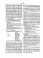
conventional alarm sensor or similar apparatus (not
shown). The PIDs are all connected to local control
unit 102 by one or two cables 108a, 108b, which may, if
desired, form a single closed loop. The particular em
bodiment discussed herein can accommodate as many as
64 PIDs, although this number is in no way critical to
the invention.
Certain PID numbers are restricted to being of partic
predetermined length of time in order to conserve re
ular types as follows:
maining battery power for continued operation of the
TABLE A
?re alarm sensors and of the system in the event of a ?re '
emergency.’ -
‘
t
PID No.
.
Another feature which may be provided in the local
0-10
ll-l2
control unit of this invention includes an alarm silence
latch settable by the operator of the local control unit
for suppressing an audible alarmv warning when the
latch is set, and means for automatically resetting the
Required Type
Commandable output PIDs
Bridge PIDs
13
14
Not used
Remote BA2 keys with
15
Bell PID v
Ordinary alarm PIDS
16-63
alarm silence latch if none of the alarm sensors con
nected to the local control unit is indicating an alarm
condition.
20
.
The alarmsystem of this invention may also include
bridge means for selectively connecting together the
remote ends of two communication circuitsextending
Commandable output PIDs are _ PIDs which send no
data to control unit102 but which can receive data from
the control unit to control a device associated with the
PID, e.g., to turn on or turn off a pump associated with
the PID. Bridge PIDs are PIDs which can be used to I
from the local control unit so that if a break occurs in
selectively connect cables 108a, 108b together to form a
either communication circuit, communication can be 25 closed loop (see discussion of FIG. 7 below). The re
re-established with alarm monitoring devices beyond
mote BA2 keyswitch PID is a control unit remote from
the break via the othercommunication circuit-and the
local control unit 102 for allowing part of the burglar
alarm system (i.e., the so-called BA2 part of the burglar
bridge connection between the ends of the two circuits.
Further features of the invention, its nature and vari
ous advantages will be more apparent from the accom
panying drawing and the following detailed description
of the invention.
alarm system) to be turned on or off from the remote
location of the BA2 keyswitch PID. The BA2 system is
typically associated with a secured area such as a safe or
* strong room within the premises protected by the re-_,
mainder of the burglar alarm system (i.e., the so-called
BAl part of the burglar alarm system). The bell PID is
the PID which controls the ringing of an alarm bell
associated with the protected premises.
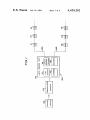
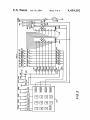
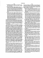
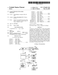
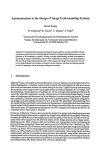
In FIG. 1, reference numbers 8, 14, 15, 16, 29, and 63
BRIEF DESCRIPTION OF THE DRAWING
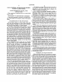
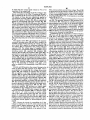
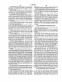
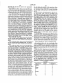
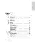
FIG. 1 is a block diagram of a typical central station
system including the local control unit of this invention.
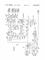
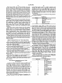
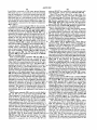
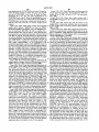
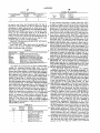
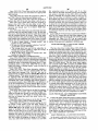
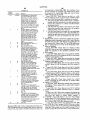
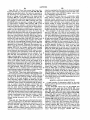
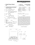
FIG. 2 is a schematic diagram of a portion of the local
control unit of this invention.‘
I ‘
are associated with the representative PIDs shown.
These reference numbers correspond to the PID num
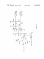
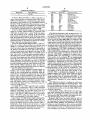
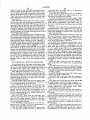
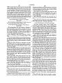
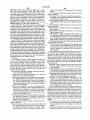
FIG. 3 is a schematic diagram of another portion of
the local control unit of this invention.
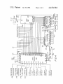
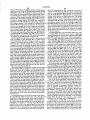
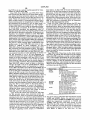
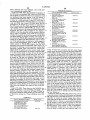
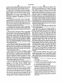
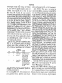
FIG. 4 is a schematic block diagram of yet another
bers discussed above. Thus PID 8 is a commandable
output PID, PID 14 is a remote BA2 keyswitch PID,
PID 15 is a bell PID, and PIDs 16, 29, and 63 are typical
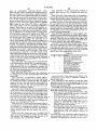
FIG. 5 is a schematic diagram of still another portion
alarm PIDs. The order and arrangement of the PIDs
of the local control unit of this invention.
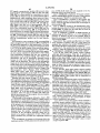
FIG. 6 is a block diagram of a typicalpoint interface 45 along cables 1080, 108b is entirely arbitrary. The con
struction of a typical PID is shown in FIG. 6 and de
device (“PID”) for use with the'local control unit of
scribed in detail below.
this invention.
'
‘There are sixteen types of ordinary alarm PIDs iden
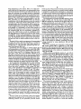
FIG. 7 is a block diagram of a typical installation of
tified
in a programmable read-only memory (“PROM”)
bridge PIDs in accordance with this invention.
associated with control unit 102 as follows:
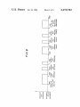
FIG. 8 is a diagram illustrating the operation of the
audio sounder which is part of the local control unit of
TABLE B
this invention.
PROM Data
Alarm PID Type
portion of the local control‘unit of this invention.
DETAILED DESCRIPTION OF THE
'
‘
INVENTION
55
As shown in FIG. 1, the local control unit 102 of this
invention is typically used in a central station alarm
system 100 including a plurality of point interface de
vices (“PIDs”) monitored and/or controlled bycontrol
unit 102, and a communicator module 104 connected to 60
control unit 102 for allowing the control unit to com
municate with a remotely located central station 106.
Typically, the PIDs and elements 102 and 104 are lo
cated _on the premises protected by the system, while
central station 106 is located a substantial distance away 65
from the protected premises.
The PIDs are typically distributed throughout the
protected premises, and each PID is connected to a
Jvau:-0
BAl movable instant
BA! movable delayed
HA1 ?xed redundant
BAl movable instant
redundant
BAl movable delayed
redundant
BA2 movable instant
BA2 movable delayed
BA2 ?xed redundant
BA2 movable instant
redundant
BA2 movable delayed
redundant
Holdup
Supervisory
Fire
4,459,582
.
5
6
TABLE B-continued
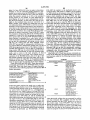
TABLE C
PROM Data
F
Alarm PID Type
No PID
5
LED No.
LED Color
Indicated Condition
DSl
D82
Green
Yellow
Protection on
Common trouble
' DS3
Yellow
Communication. failure
A BAl or BA2 ?xed PID is a PID connected to a
D54
Yellow
AC power failure
sensor which monitors a protection point which ispnor-
D55
Red
Fi‘e aiaim
mally never opened (e.g., a window foil, a glass break-
ES;
:23
age sensor, a wire screen, etc.). A ?xed PID is active at 10
D53 .
Red
point comriunication
all times. While the associated BA protection is on, an
alarm from a ?xed PID is recognized as an alarm. But
D59
Yeii°w
trouble
Piii‘" bypass
while the associated
BA
protection is off, an alarm from
_
_
32:?
‘green
ed
a ?xed PID 1s recognlzed only as a “day trouble”.
A BAl or BA2 movable instant PID is a PID con- 15
nected to a sensor which monitors a protection point
D812
D513
Red
Red
m
Point relay
li'olnt tamper
Point trouble
Point alarm
Whieh may be Opened (ea, a deer) While the asseeiLED D51 is illuminated when the BAl system is on.
ated BA Protection is 011’ Opening of the Protection
(The BA2 system must be on before the BAl system can
point causes an instantaneous alarm. While theassocibe turned on_) LED D32 is illuminated when control
ated BA Protection is Off, the protection point can be 20 unit 102 detects any of several problems such as failure
opened without causing any alarm. BA movable instant
of one or both of cables 1080, 108b or a trouble in a ?re
protection points are monitored at all times for trouble,
alarm PID. LED D53 is illuminated to indicate that
tamper, and point communications failure.
communicator module 104 is having trouble communi
A BAl or BA2 movable delayed PID is a PID con»
eating with central station 106 (steady illumination) or
nected to a sensor which monitors a protectionv point 25 to indicate that control unit 102 is having trouble com
similar to a movable instant protection point (e.g., a
municating with communicator module 104 (intermit
door) but which, when the associated BA protection is
tent illumination). LED D84 is illuminated to indicate
on, ‘allows a so-called entry time delay before opening
that the alternating current (“AC”) power has failed.
of the protection point is recognized as an alarm. A BA
LEDS DS5—DS7 are illuminated to respectively indi
movable delayed protection point is normally assoei- 30 eate that a ?re; security, or supervisory alarm has been
ated with a door to the protected premises which is
detected. LED‘ D5818 illuminated to indicate that a
physically near control unit 102 so that the subscriber
Pariimliar PID is not responding to control unit 102
can enter the premises and turn off the BA protection
(The .mimbef of the Psriiheht PID is simultaneously
during the entry time delay interval without causingan
displayed by seven segment display 114-) LED D59 is
alarm similarly, the subscriber can mm on the BA 35 illuminated to indicate that a particular PID has been
protection and leave the protected premises through the
bypassed (i-e-‘i tshipo‘i'aiiiy 011i out of the system all the
movable delayed protection point during an exit time
request of the subscriber‘). (The number of the pertlnent
delay interval without causing an alarm. In other re-
PID is simiiiiaiieoiisiy iiisPiayeii by seveii ssgiiieiii dis‘
spects, movable delayed protection points are-identical
Piay_ 114') LED D510 is‘iiiiiiiiiiiafd i0 infiicaie that a
to movable instant protection poinw
‘
40 partleular PID is in the relay on condition (i.e., that
BAl and BA2 ?xed redundant, movable instant retile K, latch’ iiiscusseii below in connection with the C
dundant, and movable delayed redundant PIDs are
line.signals’ 15 SF‘ 1." that PID)‘ (T.he number of the
similar to the corresponding non-redundant PIDs discussed above, except that an alarm from one‘ of these
pertinent
.15. simuiliglieouiljy ldisglgygd by .lslevep
segnéenidlsp ay. 1114'). d. DS hs 1_ 1. {Ire £53m?‘
devices is not, by itself, recognized as an alarm by the 45 mic to respective. y “.1 lcate at .a pamcu at
is
system Thus an alarm from one of these so-called'rebeing -tampered with’ is experiencing troilble’ or his
dundarit PIDs requires a con?rming alarm from another
dtetected an alarm? (The number of the pertinent PID 1S
PID. Redundant PIDs are therefore typically associiimiianeiiiisiy displayed by seven Segment display
aied Wiiii sensors which are characterizsd by _a rela' 50 LED DS14 (not shown) is included in cold water
iiveiy high ffiise aianii rate (6%" “iimwmc motion de'
ground detector 374 (FIG. 4), described below. This
tectors or W1nd°“’_f°11)-
_
_
' LED is illuminated to indicate a ground fault (i.e., that
A holdup PID is a PID associated Wiiii a hoidiip
the normal connection to earth or cold water ground
aiami sensoi- A supervisory PID is a PID associated
has been broken or that one of cables 108a, 108b is short
with a supervisory sensor (i.e., almost any type of non- 55 circuited to ground)
burglary, hoii'hoidiipr and non'?i'e sensor such as a
sensor for monitoring temperature or pressure in a preCess) A ?re PID is 3. PID connected to a ?re aiaim
Seven segment display 114 includes two seven-seg—
rnent light emitting diode display devices 114e, 114a
(FIG. 5), each capable of representing a decimal digit.
sensor. “No PID” means that there is no PID in the
Thus devices 1144, 114b together can display any two
system Corresponding to a/ Particular address
60 digit decimal number such as a P‘ID number.
Local control unit 102 includes light emitting diode
(“LED”) display 112, Seven Segment display 114, key- i
board 116, and audio sounder 118. These elements of
control unit 102 are shown in greater detail in FIG. 5.
Individually, these elements are all devices of types 65which are well known to those skilled in the art. LED
Keyboard 116 (shown in greater detail in ‘FIG. 5)
includes 16 buttons for entering decimal digits 0-9 and
for requesting the following functions: ON, HOURS,
BYPASS, TEST; RESET, and SILENCE. The digits
buttons are used principally to allow service personnel
and the subscriber’s personnel (any of whom are some
display 112 includes light emitting diodes numbered as
follows and indicating the following conditions:
enter multidigit code numbers (“passcodes”) for identi
times referred to herein as “authorized operators”) to
4,459,582
7
8
fying themselves to the system. Entry of a valid pass
forms no part of the present invention; (2) the particular
code while the BAl protection is on automatically turns
protocol employed cannot be revealed without making
the BA1 protection off. Entry of__a valid passcode at any
it possible for unauthorized individuals to compromise
time also activates the non-digit buttons on keyboard
or defeat security systems to be installed by the assignee
116 for a predetermined time period, during which time
of this invention; and (3) those skilled in the art can
period the authorized operator can operate those non
readily implement any one of a large number of equiva
digit buttons to command the system to perform various
lent protocols which can be employed.
functions. The ON button is used principally to turn the
The construction of control unit 102 is shown in more
BA1 protection on. The HOURS button is used (in
detail in FIGS. 2-5. The four lines of cables 108a and
combination with the digit buttons) to enter the number 0 108b are respectively connected to the upper and lower
of hours by which the normal closing time is to be
groups of terminals S, C, D, and G in FIG. 2. The two
extended before the BAl protection will be turned on.
D terminals are connected to a source of +A volts (e. g.,
The BYPASS button is principally used (in combination
a conventional direct current (“DC”) power supply
with the digit buttons) to enter the number of a PID to
circuit connected to the commercial AC power ne
be bypassed, i.e., temporarily cut out of the system so
towrk with a rechargeable backup battery for supplying
auxiliary power during failure of the commercial AC
power). Fuses 130a, 130b protect the D line circuit from
that the BA protection can be turned on even though
the bypassed PID may be erroneously signalling an
alarm. The TEST button is used (in combination with
excessive current ?ow (e. g., due to a short circuit of one
the digit buttons) to request any of several test modes.
or both of the D lines to ground). Surge suppressor 132
The RESET button is used principally to reset control 20 (i.e., a commercially available, high speed, Zener-diode
unit 102, e. g., to clear the alarm memories in the control
like device) is connected between the D line circuits
unit. The SILENCE button is used to shut off sounder
and local ground 136 to protect the D line circuit from
118 and any bells or similar audible devices in the sys
tem.
.
,
Sounder 118 is an audio tone generator for generating 25
an audio tone used to alert the subscriber to a variety of
respectively.
conditions (e.g.,-that the entry time delay interval is
The two G terminals are connected to local ground
136. Local ground 136 is connected to true earth
running, that a valid subscriber passcode has been en
I tered via keyboard 116, etc.).
ground or cold water ground 138 via parallel connected
surge‘suppressor 140 and capacitor 142. In this way any
transients induced in the system are conducted to cold
Considering now the manner in which control unit
102 communicates with the PIDs, each cable 108a, 108b
comprises four wires, known respectively as the S, C,
D, and G lines (see FIG. 2). Because these lines each
water ground‘ 138.
Within control unit 102 the source of +A» volts is
have four wires, they are sometimes referred to as
QUADs. In general, the S line is ‘used to select desired
PIDs and to receive data from the selected PIDs, the C
line is used to transmit so-c'alled relay and power com
mands to the PIDs, the D line transmits DC power from
control unit 102 to the PIDs, and the G line provides a
ground connection at controlunit ll02lfor the PIDs.
In the particular embodiment shown in the drawing,
S line signalling is accomplished by applying to the S
line pulses having voltage V1 and V2, respectively
above andibelow a quiescent "S line voltage VS. Simi
larly, C line signalling is accomplished by applying to
the C line pulses having voltage V1 and V2, respec
high voltage transients (e.g., due to lightning). The S
andv C line circuits are similarly protected from high
voltage transients by surge suppressors 144 and 146,
connected across diode 150 and capacitor 152 to a con
‘ ventional voltage regulator 154 for providing a stable
source of +5 volts for powering the digital logic ele
ments described in detail below. The output signal of
diode 150 is also used as a source of reference voltage
40
+V which is substantially equal to +A volts minus the
small voltage drop due to diode 150. Also within con
trol unit 102 the source of +A volts is connected via
diode 160 to circuits for generating three other voltages
V1, V2, and VS=VC. These voltages are related to one
45 another as follows: V1 >VS =VC>V2.
The circuit for generating VS and VC includes oper
ational ampli?er 170 connected between voltage divid
tively above and below a quiescent C line voltage VC.
ing resistors 172 and 174 which are augmented by ca
pacitors 176 and 178. Operational ampli?er 170 acts as a
Some of the S line pulses are used to address desired
PIDs. Other S line pulses are used to monitor the re
sponse of the addressed PIDs. Among the PID response
data on the S line are the following three data items: (1)
unity gain amplifier for assuring that the output of the
K and P latches mentioned above are to turn on or off
sides of Zener diode 164 retain a constant differentiai
a lamp or other device connected to the PID, or to turn
on or off a device connected to the PID which uses
despite possible ?uctuations in the voltage of the'power
powerv supplied by control unit 102 to conserve auxil
battery voltage during a prolonged AC power failure).
circuit remains at VS and VC regardless of the load on
the output. Capacitor 158 provides a connection to
whether or not the sensor connected to the PID has
ground which acts as a radio frequency (“RF”) bypass
detected an alarm condition; (2) whether or not the PID
filter for the VS, VC, V1, and V2 circuits.
has detected a trouble (e.g., a short circuit) in the associ
The circuits for generating V1 and V2 are similar to
55
ated alarm sensor; and (3) whether or not the PID has
the circuit for generating VS and VC. Series connected
detected tampering with the PID. Some of the C line
resistor 162, Zener diode 164, and resistor 166 (with
pulses are used to set so-called relay (“K”) and power
capacitor 168 in parallel with the Zener diode) form a
(“P”) latches in the addressed PIDs, while other C line
voltage dividing network. The voltages on opposite
pulses are used to reset those latches. Typical uses of the
supply source of + A volts (e.g., due to a drop in backup
Operational amplifier 180 is connected to one side of
iary battery power during a prolonged AC power fail
‘
ure.
.
Further details of the particular S and C line signal
ling protocol employed are not disclosed here for the
, following reasons: (1) the particular protocol chosen
65
Zener diode 164 to produce voltage V1, and operational
ampli?er 182 is connected to the outer side of Zener
diode 164 to produce voltage V2. In each case the oper
ational ampli?er is connected as a unity gain ampli?er
4,459,582
10
to assure that the output signal remains at V1 or V2
.
FIG. 2 circuit which controls S line voltage. Thus if 100
is subtracted from the reference number for any element
in FIG. 3, the resulting number is the reference number
of the corresponding element in FIG. 2. For example,
inverting buffer 290 in FIG. 3 corresponds to inverting
regardless of the output load.
The circuit for controlling the S line voltage is ulti
mately controlled by the S line V1 enable pin 28 and S
line V2 enable pin 27 of microcomputer 350 in FIG. 4.
The signals on these pins are respectively applied to
buffer 190 in FIG. 2.
'
conventional inverting buffers 190 and 200 in FIG. 2.
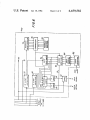
FIG. 4 shows the data processing portion of control
The output signals of buffers 190, 200 are respectively
unit 102. The principal element of this apparatus is mi
applied to conventional solid state switches 192, 202.
crocomputer 350. Although any suitably programmed
Pull-up resistors 194, 196, 204, 206 assure that sufficient 0 microcomputer may be used, in the particular embodi
current is available to drive each succeeding element in
each of the above-described circuits. Solid state switch
192 connects point 210 to the source of V1 described
ment described in, detail herein. microcomputer 350 is a
above when microcomputer 350 signals that a V1 pulse
Clara, ‘Calif. An illustrative program for microcomputer
model 8050 microcomputer commercially available
from National Semiconductor Corporation of Santa
I is to be applied to the S line. Similarly, solid state switch 15 .350 is set forth in the micro?che appendix to this speci?
202 connects point 210 to the above-described .sourceof
V2 when microcomputer 350 signals that a V2 pulse is
cation and is discussed in‘ detail below.
Considering‘ ?rst the organization of microcomputer
to be applied to the 5 line. Unless thus connected ‘to V1
350, there are 40 input and/or output pins numbered
or V2, point 210 is at voltage VS as a result of resistor
140. Pin 1 is the toggle zero or T0 pin which is con
212 connecting that point to the above-described source 20' nected to the output of comparator 260 in FIG. 2. Pins
of VS.
.
. 2 and 3 are frequency control pins, between which
The signal at point 210 is processed by the circuitry
‘ frequency control crystal 352 is connected. Crystal 352
connected between points 210 and 240 to amplify the
establishes the basic clock frequency of microcomputer
available current without altering the voltage. The sig
350. Pin _3 is also connected to ground via capacitor 354.
nal at point 210 is applied to operationalampli?er 220 25 Pin 4 is the reset pin which is connected to manual reset
via resistor 214 in cooperation with resistor 216 and
switch 356 via: diode 358. When reset switch 356 is
capacitor 218. The output signal of ampli?er 220 is
closed,_microcomputer 350 resets and begins its operat
' connected to a conventional push-pull ampli?er circuit
“ing routine or program from the start as though it were
including resistor 222, capacitor 224, transistor 230,
commencing operation for the: ?rst time. Pins 5 and 6
resistors 232 and 234,. and transistor 236. Point 240 is
are the single step and‘ interrupt pins, respectively.
connected to a point intermediate resistors 232 and 234.
These pins are not used in this embodiment and are
The signal at point 240 is connected to the S line via ' therefore connected to +5 volts. Capacitor 368 is a
resistor 242, and the S line signal is fed back to opera
?lter capacitor. 'Pin 7 is the internal/external select pin.
tional ampli?er 220 via resistor 226. The feedback input
With jumper 360 removed (as it is‘in the disclosed em
to operational ampli?er 220 is connected to’ ground via 35 bodiment), program instructions are read from a read
resistor 228. Thus the voltage on the S line is either V1,
only memory (“ROM”) which is internal to microcom“
V2, or VS, depending on whether a V1 pulse, a~_V2 ‘ put-er 350. Pin 8'is‘ the read control or RD pin which
pulse, or neither is to be transmitted to the PIDs via the
carries a signal for instructing other devices connected
to ‘the microcomputer that the microcomputer is ready
Control unit 102 monitors the current ?owing in the 40 to read data or other information from those other de
S line to detect the data response of the PIDs..This is
vicespPin 9 is not used. Pin 10 is the write control or
S line.
-
I
-
‘
.
accomplished by monitoring the voltage drop across
’ WR pin which carries a signal for instructing other
resistor 242. The voltages on opposite sides of resistor ‘devices connected'to the microcomputer that the mi»
242 are applied to the input terminals of operational
crocomputer is ready to write data or other information
ampli?er 250 via resistors 244 and 246. The point inter 45 to those’other devices. Pin 11 is not used. Pins 12—19 are
mediate resistor 246 and operational ampli?er_v250 is
the eight‘pins of an eight bit data bus, the individual
connected‘ to ground via resistor 248 and capacitor 249.
leads of‘which are respectively designated ‘DBO-DB7.
The operational ampli?er output signal is. fed back to
Resistors 364'are pull-up resistors for the data bus leads.
the operational ampli?er via resistor 252 and capacitor‘? Pin 20 is the ground pin and is connected to ground as
254. The operational ampli?er output signal is also con
shown. Capacitor 366 is also connected between pins 4
nected to ground via resistor 256 and to one input termi
and 20. Pins 21-24 and 35-38 are the eight pins of input
‘ nal of conventional comparators 260 and 262. Thus
/output port 2. The individual leads of input/output
operational ampli?er 250 produces an output signal
port 2 are respectively designated P20-P27. Pin 25 is a
proportional to the voltage drop across resistor 242.
control line needed for communication‘ between mi»
Comparators 260 and 262 each compare the output 55 crocomputer 350 and input/output expanders 390 and.
signal of operational ampli?er 250 to a reference signal
400 in the conventional manner. Pins 26 and 40 are
+X volts or +Y volts to provide a window within
power supply pins and are thus; connected to +5 volts.
which valid PID response data must fall. The output
Pins 27-34 are the eight pins of input/output port 1. The
signals of comparators 260 and 262 are respectively
individual leads of input/output port 1 are designated
applied to pins 1 and 39 of microcomputer 350 in FIG. 60 P10-P17. Leads P10 and P11 are respectively con“
4. Pull-up resistors 264, 266 are used to assure that there
nected to inverting buffers 200 and 190 in FIG. Land
is suf?cient current applied to microcomputer pins 1
leads P12 and P13 are respectively connected to invert“
and 39.
ing buffers 300 and 290 in FIG. 3. Lead P14 is con"
FIG. 3 shows the circuit for controlling the C line
nected to tamper detector 370 which may be a convenw
voltage in response to C line V1 enable and C line V2 ‘ tional circuit for detecting-when someone is trying to
enable control‘ signals appearing on pins 30 and 29,
respectively, of microcomputer 350. The circuit of
FIG. 3 is substantially identical to the portion of the
gain access to the interior of control unit 102. Lead P15
is connected to AC power detector 372 which may be a
conventional circuit for detecting an AC power failure.
4,459,5 82
11
12
resistors 431-437 are connected in series between each
Lead P16 is connected to cold water ground detector
374 which may be a conventional circuit for detecting
that the connection to cold water ground has been dis
turbed. Lead P17 is connected to low battery detector
376 which may be a conventional circuit for detecting
LED DSl-DS7 cathode and bits P50-P53, P60-P62.
After P70 has been selected for a short time, it is
unselected (thereby turning off LEDs DS1-DS7) and
P71 is selected (logical 0) instead. Selection of P71 turns
an extended AC power failure). Pin 39 is the toggle 1 or
on transistor 440 in conjunction with resistors 442 and
444, thereby applying power to the anodes of LEDs
T1 pin which is connected to the output of comparator
DS8-DS13. While P71 is thus selected, the appropriate
262 in FIG. 4.
In addition to microcomputer 350, the data process
ones of P50-P53, P60, and P61 are selected to illuminate
the desired ones of LEDs DS8-DS13 in a manner anal
ogous to the illumination of LEDs DS1-DS7.
that the auxiliary battery power supply is low (e. g., after
ing portion of control unit 102 includes programmable
read-only memory or PROM 380, input/output expan
P71 is unselected after a short time (thereby turning
off LEDs DS8-DS13), and P72 is selected. This turns
on transistor 450 in conjunction with resistors 452 and
454 and thereby applies power to the anode of seven
der 390, and input/output expander 400. PROM 380 is a
conventional 256 by 4 bit PROM. PROM 380 is ad
dressed by the signals applied to its address pins A0-A7.
segment display device 114b. While P72 is thus selected,
The four bits stored in the selected address location are
applied to data pins Ql-Q4. Data pins Q1-Q4 are re
the appropriate ones of P50-P53 and P60-P62 are se
lected to illuminate the desired segments of display 114b
spectively connected to data bus leads DBO-DB3 of
to cause a desired decimal digit to appear.
microcomputer 350. The signal applied to the S1 pin
After display 114b is energized for a short time as
commands PROM 380 to supply the addressed data to
discussed above, display 114a is similarly energized by
data pins Q1-Q4 for reading by microcomputer 350. To
selection of P73 and appropriate ones of P50-P53 and
P60-P62. Selection of P73 turns on transistor 460 in
conserve power, PROM 380 is only turned on when
needed. This is controlled by the P70-P73 output sig
nals of input/output expander 400 in conjunction with
the circuit including resistors 382 and 384, transistor
386, and capacitor 388. The P70-P73 output signals of
expander 400 are also applied to the S2 pin of PROM
380 aslan enabling signal.
conjunction with resistors 462 and 464.
Commands and data entered by an operator via key
board 116 are also read as a result of the cyclic selection
- of P70-P73. While P70 is selected, power is applied to
one contact of all the normally open switches associated
7
with the horizontal row of keyboard 116 buttons includ
ing the 0 button. If any button in that row is operated
while‘. P70 is thus selected, the associated one of
Each of input/output expanders 390 and 400 is a
commercially available device (e.g., a model .8243 I/O
expander available from Intel Corporation of Santa
P40-P43 is energized (logical 1). Otherwise P40-P43
remain at ground (logical 0) as a result of the operation
Clara, Calif.) for transmitting data between the four pins
of input/output expander port 2 (i.e., pins 8-11) and a
selected one of port 4 (i.e., pins 2-5), port 5 (i.e., pins 1
and 21-23), port 6 (i.e., pins 17-20), and port 7 (i.e., pins
of resistors. 470-477. The four rows of keyboard buttons
are energized one after another as a result of the cyclic
selection of P70-P73. The identity of the button de
pressed at any given time is known from the concurrent
row and column information represented by P70-P73
and P40-P43. The data latched into P40-P43 is trans
13-16). Selection of the input/output expander to com
municate with microcomputer 350 is controlled by the
chip select or C5 signals appearing at microcomputer
350 pins 35 and 36, respectively. These chip select sig
40 mitted to microcomputer 350 each time a different one
nals are applied to CS pin 6 of the input/output expan
of P70-P73 is selected.
ders. The input/output expanders latch data applied to
' Input/output expander 400 is used to address PROM
380 as discussed above and to control relay element 402,
their ports 4-7 so that this data remains ?xed until
changed by new data. Power is applied to pin 24 of each
input/output expander, and pin 12 of each input/output
expander is connected to ground. A capacitor 392 is
connected between pins 12 and 24 of each input/Output
expander. The details of communication between mi
crocomputer 350 and the input/output expanders are
conventional and are not important tothe present-in
vention.
Input/output expander 390 is used to control displays
112 and 114 and to accept data from keyboard 116.
These elements of local control unit 102 are shown in
detail in FIG. 5. As discussed in greater detail below,
microcomputer 350 selects each bit P70-P73 of input
/output expander 390 port 7 one at a time in a continu
ously repeating cycle. Each P70-P73 bit is selected for
45
test element 404, and sounder 118. (Spare 406 is not
used.) Relay element 402 is typically a conventional
direct wire connection to a police or ?re station. Test
- element 404 is part of low battery detector 376. When
commanded by P41 of input/output expander 400, test
element 404 effectively disconnects the system from AC
power in order to test the auxiliary battery. If the bat
tery is inadequate, low battery detector 376 will apply a
low battery signal to microcomputer 350. Sounder 118
(FIG. 5) is energized when input/output expander 400
bit P43 is selected (logical 1). This logical 1 signal is
inverted by inverter 408 so that current ?ows through
sounder 118 from the positive voltage source.
The construction of a typical PID is shown within
the broken line in FIG. 6. Although the PID shown in
FIG. 6 is assumed to be one of alarm PIDs 16-63, the
a predetermined relatively short interval of time (e.g., a
small number of milliseconds) and is logical 0 while thus 60 other possible types of PIDs include similar elements.
The PID is connected to the C, S, G, and D lines of
selected. Selection of the P70 bit turns on transistor 410
in cooperation with resistors 412 and 414. This applies ‘
QUAD 108a or 108b as shown. The D line provides a
source of +A volts for powering the PID and, when P
power to the anodes of light emitting diodes DS1-DS7.
latch 92 is set, the alarm sensor (not shown) connected
At the same time that bit P70 is selected (logical O), the
appropriate ones of input/output expander 390 bits 65 to the PID. The G line provides a source of ground
potential for the PID. The S line signal is applied to S
P50-P53 and P60-P62 are selected (logical 1) to cause
current to ?ow through the desired ones of LEDs
DS1-DS7. A respective one of inverters 421-427 and
line detector 70, which may be a conventional threshold
detector circuit for detecting information pulses on the
13
4,459,582
S line. S line detector 70 applies address and data pulses
detected on the S line to address pulse counter 72 and
data pulse counter 74, respectively. Pulse counters 72
and 74 may be conventional binary digital pulse count
ers which produce binary coded output signals repre
sentative of the number of pulses which have been ap
plied to them. The address identifying the PID is stored
in address storage register 78, which may comprise a
plurality of on/off switches for collectively represent
ing a binary number. The contents of counter 72 and
register 78 are compared by comparator 76, which may
be any conventional device for comparing twobinary
numbers and producing an output signal only when the
two numbers being compared are equal. The output
14
latch 92, depending on the concurrent contents of
counter 74. Steering logic 88, like output gate logic 80,
may be a conventional signal steering or switching de
vice. K latch 90 and P latch 92 may be conventional
bistable multivibrator o'r flip-?op devices. The output
signals of the P ‘and K latches may be used for any
desired purposes, such as controlling an indicator light
associated with the PID. In the particularly preferred
embodiment shown in FIG. 6, the output signal of P
latch 92 is applied to conventional gate 94 to control the
?ow of power from the D line to the alarm sensor asso
' ciated with the PID. As discussed in detail above, this
allows local control unit 102 to cut off power to certain
alarm sensors when desired, such as during a prolonged
‘ signal of comparator 76 is applied as an enabling signal 15 AC power failure.
to output gate logic 80 and steering logic 88. Thus de
vices 80 and 88 are enabled only when the number of
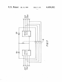
As mentioned above (see discussion following Table
A), bridge PIDs 11 and 12 can be used to selectively
connect together the remote ends of QUAD cables 108a
and 108b to form a closed loop. This is illustrated in
address pulses received by the PID via the S line equals
the address of the PID stored in register 78.
A data signal from the alarm sensor connected to the 20 FIG. 7 in which PID 11 is connected to the remote end
PID is applied to data detector 82. A typical alarm
of QUAD 108a and PID 12 is connected to the remote
sensor data signal has three voltage levels (e.g., a high
end of QUAD 108b. Each of PIlDs 11 and 12 may be
voltage if the sensor detects an alarm, a low voltage if
similar to the PID shown in FIG. 6. Preferably, PIDs 11
the sensor is in ‘a trouble condition, and an intermediate
and 12 are both mounted in a single device. The four
voltage if the sensor is operating properly and no alarm 25 normally open contacts of fourpole relay 96 are respec
has been detected). Accordingly, data detector 82 may
tively connected between the D, S, C, and G lines of
be a conventional threshold detector circuit for identi
QUADs 108a and 108b. The coil of relay 96 is con
fying the information represented by the alarm sensor
nected between the K latch output of each bridge PID
data signal and producing a plurality of output signals,
and‘ the D line of the associated QUAD. (Diodes 98a
each of which is representative of a respective one of 30 and 98b isolate the D lines of the QUADs from one
the possible sensor conditions (e. g., alarm, trouble, nor
another while the contacts of relay 96 are open.) The
mal). The output signals of data detector 82 are stored
contacts of relay 96can therefore be closed by setting
in data storage register 84, which may be a conventional
the K latch of either PID 11 or 12. When the contacts
binary storage register. If desired, data storage, register
of relay 96 are thus closed, the remote ends of the D, S,
84 may be erased each time the output signal of compar 35 C, and G lines of QUAD 1080 are connected to the
ator 76 switches to its disabling state to effectively reset
remote‘ ends of the D, S, C, and G‘ lines of QUAD 108b.
the PID after each interrogation of the PID by local
If abreak occurs in either QUAD 1080 or 10811 which
control unit 102. Data pulse counter 74 may also be
prevents local control unit 102 from receiving data from
reset at the same time if desired.
some of the PIDs on that QUAD, local control unit 102
sends a command to the bridge PID 11 or 12 associated
The output signals of data pulse counter and data‘
storage register 84 are applied to output gate logic 80.
When gate logic 80 is enabled by comparator 76 as
discussed above, it applies the information represented
by a selected one of the output signals of data storage
with the other unbroken QUAD to set the K latch of
that bridge PID. This energizes relay 96, thereby con
necting the. remote ends of QUADs 108a and 108b to
gether. Local control unit 102 can now communicate
register 84 to line 81. The data storage register 84 out 45 normally with PIDs beyond the break in the broken
put signal selected is determined by the contents of data
QUAD via the unbroken QUAD and the connection
pulse counter 74. For example, when data pulse counter ‘between the QUADs established by the bridge PIDs.
74 has counted one data pulse, the signal on the left
Use of the above-described bridge PIDs to circum
most output lead of data storage register 84 is applied to
vent a fault in either QUAD has several important bene
line 81; when data. pulse counter 74 has counted ‘two 50 fits. First, it provides the protection of redundant con
data pulses, the signal on the next left-most output lead
nections between local control unit 102 and the PIDs
of data storage register 84 is applied to line 81; and so on
without the need for expensive duplicate wiring. Sec
until as many data storage register 84 output signals as
ond, no separate, QUAD fault detection circuitry is
are desired have been applied in turn to line 81. The
required.‘ The presence of a QUAD fault is known from
signal on line 81 is transmitted back to local control unit
the inability of local control unit 102 to receive data
102 via the S line. In this way local control unit 102
from one or more PIDs, and the fault is then promptly
interrogates the PIDs and receives data from the PIDs
corrected by operation of one of the two bridge PIDs.
via the S line.
.
Third, installations can be provided with or without this
As mentioned above, the K and P latches of the PIDs
feature, as desired, simply by including or not including
are controlled by pulses on the C line. The C line signal 60 ‘bridge PIDs 11 and 12. One common system design
is applied to C line detector 86, which may be similar tov
meets the need for both types of installations.
S line detector 70. The output signals of C line detector
Communicator module 104 is not shown in detail
86, which respectively indicate latch set and latch reset
because‘it may be conventional and because it does not
commands, are applied to steering ‘logic 88. Steering
form part of the present invention. In general, however,
logic 88 also receives the output signals of data pulse
the function of communicator module 104 is to provide
counter 74 and, when enabled by the output signal of
an interface between microcomputer 350 and the rela
comparator 76 as discussed above, applies the output
tively long communications link to central station 106.
signals of C line detector 86 to either K latch 90 or P
When appropriately instructed by the WR, P26, and
15
4,459,582
16
sive of PIDs 0-15 which are each required to be of a
P27 signals, communicator module 104 converts data
received from microcomputer 350 via data bus leads
particular type as set forth above).
Line 7: COMRAM is equated to 16 because commu
DBO-DB7 to a form suitable for transmission to central
nicator module 104 is allowed 16 bytes of data random
access memory (“RAM”) in microprocessor 350.
station 106 via whatever type of communications link is
employed (e. g., radio, telephone, direct wire, etc.) Simi
appropriately instructed by the RD, P26, and P27 sig
Line 8: MAXRAM is equated to 255 because the
RAM required as part of microcomputer 350 has 256
bytes. A byte is eight bits and is the basic word length in
nals, passes that data on to microcomputer 350 via
microcomputer 350.
larly, communicator module 104 converts data received
from central station 106 to DBO-DB7 form and, when
.
Line 11: PIDO is equated to 80 hexadecimal (“H”)
DBO-DB7. Communicator module 104 may use a por
tion of the information stored in PROM 380, and for
because the status byte for PID 0 is stored in data RAM
from communicator module 104 to input/output expan
location 80H. A status byte for each PID is stored in
succeeding data RAM locations.
Line 13: EXMAP is equated to 0COH because an
der 400. Communicator module 104 also uses the reset
existence map for the ‘PIDs (i.e., a 1 or O to indicate the
signal from switch 356 so that both microcomputer 350
presence or absence of each of 64 possible PIDs) is
stored in successive RAM memory locations beginning
with location 0COH.
Lines 20-25: The symbols speci?ed here are respec
tively equated to registers (“R”) 4-7. This means, for
that purpose microcomputer 350 is programmed as
described below to transmit PROM address information
and the communicator module can be reset simulta~
neously.
An illustrative source program (with corresponding
object program) for microcomputer 350 is provided in
the micro?che appendix to this speci?cation. The lines
of the program listing are numbered consecutively from
1 to 5776 in the third column of the micro?che‘appen
dix. (A small portion of the program (i.e., lines 897-1269
and 1387-1495) is not included in'the micro?che appen
25
example, that wherever the symbol SYSTMl appears,
that symbol should be interpreted as register 4.
Lines 26-27: The symbol for the word “at” means
“indirect”. Thus the comment for line 26 should be read
as “INDIRECT ADDRESS OF SYSTEM 1 REG”.
Lines 30-160: These lines equate various symbols
dix for reasons explained in detail below.) The object
code information comprises the ?rst two columns of ' with data RAM locations. Thus line 32 equates the
RAM address symbol KSBl with data RAM locations
information in the program listing. The object code
information will not be speci?cally discussed herein 30 20H, so that when KSBI is used in the program as a
RAM address, that symbol will be interpreted as data
because it is the exact equivalent of the‘ source code
RAM location 20H. The capability of having two com
which will be discussed. The source code information
municator modules is not used in the disclosed embodi
begins in the fourth column of the program listing. The
forms of the source code statements used in the program
are conventional and are explained in detail, for exam
ment, so lines 126-143 ‘can be ignored. Lines 150-157
are part of the de?nition of specialized PIDs 0-15 as
ple, in the publication MCS-48 Family of Single Chip
discussed above.
_
Microcomputers; User’s Manual, Intel Corporation,
Santa Clara, Calif., April 1979. Throughout the pro
Lines 164-205: These lines equate various symbols
with locations in PROM 380. Thus line 166 equates the
gram listing, information to the right of a semicolon is
comment information which forms no part vof the pro
’ PROM address symbol FDIGl with PROM 380 loca
tion 40H, so that when FDIGl is used in the program as
a PROM address, that symbol will be interpreted as
gram but which serves to explain the program. ‘
PROM location 40H.
Starting near the bottom of page 172 of the micro
?che appendix listing and continuing through page 175
is an alphabetical tabulation of all the symbols de?ned in
the program, with the hexadecimal (base 16) equivalent
particular binary numbers which are used as masks to
45 test or set particular bits in other data. The comments
value of each symbol. Following page 175 are 17 pages
on which all of the symbols de?ned in the program are
listed again with the program line number: of every
reference to each symboI. A line number followed by
the symbol “if” is the line number at which the symbol
is de?ned. These two lists of variables and other sym
bols do not form part of the program,‘ but are program
ming and diagnostic aids.
‘
The ?rst part of the program listing (i.e., lines 1-666)
are statements which equate (“EQU”) symbols used in
the program to particular numbers. For example, line 6
states that the symbol PIDCNT, whenever encountered
'
Lines 210-246: These lines equate various symbols to
50
‘associated with each line indicate the signi?cance of
particular'bits in the associated data. For example, line
212 is a mask for testing the so-called “external BAI
/internal” option bit stored in PROM 380. An explana
tion of the meaning and use of this particular option is
given below in the discussion of lines 1997-2025.
Lines 250-286: These lines equate various symbols to
code numbers (sometimes called passcode numbers)
which are transmitted to the central station to report
55 various conditions in the system.
in the program, is to be interpreted as the decimal num
Lines. 2294-401: These lines equate various symbols to
particular binary numbers which are used as masks to
test or set particular bits in other data. The comments
decimal (base l6) number. Although the comments
tively, of microcomputer 350. In particular, line 296 is
associated with each line indicate the signi?cance of
ber 48. A number is a decimal number (base 10) unless
followed by B or H. A number followed by B is a binary 60 particular bits in the associated data. For example, lines
294-299 de?ne masks for use in testing P14-P17, respec»
(base 2) number, and a number followed by H is a hexa
used to test P14, and FIG. 4 shows that tamper detector
contained in the micro?che appendix listing are be
370 is connected to P14 as is consistent with the com»
lieved to be largely explanatory of lines 1-666, addi
tional comments are provided here regarding selected 65 ment in line 296. In line 312 the comment “PORT4-i”
refers to port 4 of input/output expander 400. In lines
lines:
‘
323 and 336 the comment “U3 8243” refers to input
Line 6: PIDCNT is equated to 48 because this is the
/output expander 390.
maximum number of PIDs allowed in the system (exclu
4,459,582
17
a
Lines 404-407: These lines equate two symbols used
to test two commands which can be sent from the cen
‘
18
(FIG. 4) and controls output devices 112, 114, 118, 402,
and 404 via input/output expanders 390and 400.
tral station to control part of the operation of local
control unit 102.
Lines 411-434: These lines equate various symbols to
particular values to control various aspects of the de
vice such as the length of signal pulses on the S and C
2.. PID communication routine (not reproduced in the
micro?che appendix for thereasons discussed in detail
lines, the length of sounder 118 blasts, etc.
Lines 440-584: These lines equate various symbols to
particular binary numbers which are used as masks to
test or set particular bits in other data. The comments
As mentioned above, the timer interrupt routine is
called every X milliseconds. Program control remains
in thetimer interrupt routine less than X milliseconds.
After processing of the front end program, microcom
associated with each line indicate the signi?cance of
puter 350 reverts to working on the main program for
particular bits in the associated data in a manner similar
to that discussed above in connection with lines 210-246
the remainderof the X-millisecond time interval.
Although the comments contained in the micro?che
15 appendix program listing are believed to be largely
and 294-401.
below): This portion of. the timer interrupt routine con
trols actual physical communication with the PIDs via
the S and, C lines.
Lines 588-662: These lines equate various symbols
used in the so-called timer interrupt or front end pro
gram discussed in detail below.
_
‘
.
,
ments are provided here regarding selected lines of the
.
program.
gram. The main program includes the following princi
.
=explanatoryof the source program, additional com
The actual operating part of the source. program
begins at line 669. The program basically comprises a 20
main program and a timer interrupt-or front end pro
pal parts:
,
,
1
a
a
" MAIN PRQGRAM—_START ROUTINE '
Lines 669-672, 1271-1274: These lines clear all loca
tions of the data- RAM to zero.
Lines 1278-1350: These lines read data from PROM
v
1. Start routine (chiefly lines 669-672, 1271-1362, , 380\which indicates whetheror not the associated in
1543-1556): This routine is used only when the program, 25 stallation includes a‘PID for each of the possible PID
is run for the ?rst time or whenever reset button 356
addresses.
;
.
a »
1
Lines 1355-1359:. These lines preset and start the
.2. Input routine (chie?y lines 1560-1924): Thisirou
timertinterrupt counter. This counter is used to. inter
tine sets up input data for processingby the process
rupt the, main program every X milliseconds to initiate
routine below. This routine accepts data from tamper 30 processing of the-timer interrupt routine as described
(FIG. 4) is operated.’
,
.
.
-
detector 370, AC power detector 372, . cold water
. ground detector 374, and low battery detector 376. "This
routine also sets up input data based on PID and key
board data stored in the RAM. -
t.
above.
-
t
;
t
t
.
Lines 1361 and 1370-1376 (line (1362 is discussed after
line 1383 below): .These lines initialize the program
i - statusword (:“PSW”) for the timer interrupt routine.
3. Process routine (chie?y lines 1928-2363): This 35 .Lines 1378-1381: Theselines initialize the PID. ad
routine processes the information read in by theinput
dress counter. (“ADDCNT”) with the number of PIDs
routine and formulates appropriate responsesto. that - in the installation. This is done so that microcomputer
information. For example, the process routine monitors
v350=will interrogate all the PIDs in the installation.
. expiration of the entry and exit-time delays, it sets and
1 Line 1383: This line directs microcomputer 350 to
resets data latches whichiindicate‘the occurrence of 40 perform a portion of the timer interruptroutine.
alarm conditions, and it controls and monitors. the late
close timer.
'
Lines l362.and 1543-1556: These lines preset the AC
. timerypreset the start‘timer, turn on the BA1 system,
~
4. Output routine (chie?y lines 2367-3831): This rou
preset thebell ring timer, and preset the bell ring
tine sets up-output data for use in controlling the various .1 counter. Elsewhere in the program, the‘ ACttimer is
outputs of the system including LED display 112, seven 45 incremented (up' to a predetermined amount such as
segment display 114, sounder .118, the commandable
output PIDs, the bell PID, the BA2 remote keyswitch
module, relay device 402 (FIG. 4), and test device 404
(FIG. 4). The output routine also sets up output data for
four hours) each time a predetermined time interval
passes with no loss of AC power, and decremented each
time a predetermined time interval passes with no AC
.power. Inthis way, the AC timer represents the amount
controlling the C line signals transmitted to the PIDs 50 of time the system has been operating with AC power.
and the alarm and other information going to communi
The ACtimer can therefore be used as an indication of
cator module 104 for transmission to central station 106.
the level of the charge on the backup battery. The start
timer is used to prevent the system from responding to
5. Miscellaneous (lines 1497-1539): These lines are
merely a programming convenience to facilitate. jumps
alarms during the. ?rst few seconds that the system is
between the two memory banks in the particular mi 55 turned on. This allows the systemto settle down before
crocomputer 350 employed in theembodiment shown i alarm indications are acted upon. The BA1 protection is
and described herein. No further detailed reference will
‘ turned on and the bell associated with the system rings
be made to these lines.
I V i
whenever reset button 356 is operated and the. start
The main program is interrupted at regular time inter
routine is therefore performed. In this way an alarm is
produced in the event that the housing of local control
vals (typically every X milliseconds, where X is an
arbitrary small number) to perform portions-of the timer \unitt102 is ripped open and reset button 356 is operated.
interrupt routine. The timer interrupt routine includes
the following principal parts:
i
'
MAIN, PROGRAM~INPUT ROUTINE
Lines 1560-1563: These lines store timing bits which
1. Initial portion of timer interrupt routine (lines
675-881): This portion of the timer interrupt routine 65: are set up in the timer interrupt: routine mentioned
controls clock data which in turn controls various timed
functions throughout the program. This routine also
reads keyboard data from input/output expander 390
above: In this ‘way the timer interrupt routine ‘provides
timing information which is used to control a variety of
timed operations in the remainder of the program. The
4,459,582
19
least signi?cant bit of CLKTMP is set every N times the
20
Lines 1702-1729: These lines input and debounce the
timer interrupt routine is called; the next least‘ signi?
output signal of cold water ground detector 374 (con
cant bit of CLKTMP is set every M times the least
nected to bit 6 (“B6”) of port 1 (“P1”) of microcom
signi?cant bit is set; the next least signi?cant bit of
puter 350).
CLKTMP is set every P times the preceding bit is set;
and so on. In this way the various bits of CLKTMP (or
CLOCK) have various time values and can be used to
indicate that time intervals of various lengths have
Lines 1733-1745: These lines make certain that a
PROM 380 is plugged into the circuitry of local control
unit 102.
Lines 1750-1762: These lines test the status of the
bridge PIDs to determine whether they are connected
elapsed.
Lines 1567-1596: These lines control the keyboard
enable timer register (“KBETR”) so that the TEST,
BYPASS, RESET, SILENCE, ON, and HOURS but
to one another due to a break or fault in either QUAD
1080 or 108b.
Lines 1767-1775: These lines check the proper func
tioning of communicator module 104 in order to set up
data to illuminate LED DS3 (the telecommunications
tons on keyboard 116 (FIG. 5) will be enabled for a
predetermined time interval after a valid passcode has
been entered by an authorized operator of local control
failure indicator) of LED display 112 if communicator
module 104 indicates a problem.
unit‘ 102. In general, the digit buttons on keyboard 116
Lines 1780-1880: These lines process data received
are always enabled, but the other keyboard buttons are
only enabled after a valid passcode has been entered. At
from the remote BA2 keyswitch module (i.e., PID 14)
and stored in the data RAM to turn on or off the BA2
lines 1578-1579 a counter for controlling sounder 118
(also called “SONALERT” in the comments in the 20 system as requested by the PID 14 data (if the system is
micro?che appendix) is preset when KBETR times out
in a condition in which the request can be honored) and
to cause a short audio tone from sounder 118 to indicate
‘ to generate the passcode number of the BA2 keyswitch
that the non-digit buttons of keyboard 116 have been
module operator who requested that the BA2 protec
tion be turned on or off. As mentioned above in the
disabled. At lines 1584-1594 a manager bit (indicating
that the non-digit keyboard keys were enabled in re~ 25 “discussion following Table A, the BA2 keyswitch mod
ule (not shown in detail herein because it forms no part
sponse to one of four higher level passcodes), a hostage
bit (indicating that the non-digit keyboard keys were
of the present invention) is a PID-type device including
*a keyboard and microprocessor and‘which is typically
enabled in response to a passcode accompanied by a
hostage code), and display enable bits (used to enable
some display test functions) are cleared.
'
’ located near the area protected by the BA2 system (e.g.,
30 a vault or storeroom inside the premises protected by
the BAl system). An operator wishing to turn the BA2
protection on or off enters his passcode via the BA2
Lines 1600-1612: These lines input and debounce the
output signal of tamper detector 370 (connected to bit 4
keyswitch module keyboard. The BA2 keyswitch mod
(“B4”) of port 1 (“P1”) of microcomputer 350).
‘ Lines 1616-1644: These lines input'and debounce the
output signal of low battery detector 376 (connected to
bit 7 (“B7”) of port 1 (“P1”) of microcomputer 350).
The fault 26 bit referred to at lines 1634-1635 is a'bit
which indicates detection of faults 2-6. As the comment
at line 477 shows, these faults are low battery, cold
water‘ ground fault, PROM missing, bridge PIDs con‘
nected to one another (due to a break or fault some
where along either QUAD 1080 or QUAD 1081)),- and
ule validates the passcode and sets up the ?rst four bits
"of the data to be transmitted back- to local control unit
102'via the S line to represent (?rst bit) the fact that a
change of state of the BA2 system has been requested
and (next three bits) a code number for the person who
requested the change of state. A request from the BA2
40 keyswitch module is merely a request to change the
state of the BA2 system from whatever its present con
dition to the other condition. Local control unit 102
AC off for four hours. (See also the list of fault condi
tions in Table H below.) At line 1642 the person number
subroutine (“PNSOX”), discussed below in relation to“ 45
lines 5696-5732, is called to set up data which ultimately
honors the BA2 keyswitch request and changes the
state 'of the BA2 system only if the condition of the
system (as monitored by local control unit 102) permits
104 to indicate that a low battery has been detected.
Lines 1648-1698: These lines input and debounce the
the BA2 system to change state. At lines 1782-1789 the
data received from PID 14 is'read from the data RAM
and tested to determine whether a request for a change
of state has been made. At line 1811 the program deter
output signal of AC power detector 372 (connected to
mines whether the BA2 system is now on or off. Lines
causes apasscode to be sent to communicator module
1815-1822 are performed if the BA2 system is now off
These lines also control AC loss timer register " and the BA2 keyswitch request is therefore to be inter
preted as a request to turn on the BA2 system. The
(“ACLTR”) to increment that register at predeter
BAXON subroutine at lines 4760-4845 determines
mined time intervals (up to a maximum amount) while
AC power is on, and to decrement that register atpre 55 whether the system is in condition to have the BA2
system turned on, and if so, turns on that system by
determined time intervals while AC power is off.
turningon the BA2 ON bit in system status word
ACLTR therefore provides a measure of how long the
SYSTM2. Lines 1827-1877 are performed if the BA2
AC power has been off and consequently how» much
system: is. now on and the BA2 keyswitch request is
power remains in the backup battery. ACLTR is used
bit 5 (“B5”) of port 1 (“P1”) of microcomputer '350).
elsewhere in the program to turn off power to the alarm 60 therefore to be interpreted as a request to turn off the
BA2 systemsThe reference to “nested” in the com
sensors or other devices associated with certain-PIDs
ments associated with these lines is explained below in
the discussion of lines 4144-4209. At lines 1835-1837
the BA2 system is turned off by turning off the BA2 ON
devices (e. g., ?re alarm sensors). This is done by turning 65 bit in system status word SYSTM2. At lines 1839-1843
.the BAZlate close timer is preset. At lines 1845-1866
off the P latch in the PIDs associated with the sensors to
any BA2 PIDs which have been bypassed (i.e., effec
be turned off (see discussion of the P and K latches
tively removed from the system) are put back in the
mentioned above in relation to the C line signals).
(e.g., burglar alarm sensors) after a prolonged AC
power failure in order to conserve remaining battery
power for continued operation of other more important
4,459,582
21
22
system to prevent any BA2 PID from being perma
nently bypassed. And at lines 1869-1877 data is set up to
send to central station 106 the passcode of the person
turning off the BA2 system, unless the system has only
“Sans” service (i.e., the class of service in which only
alarms and not openings and closings are reported to the
of the BA1, BA2, ?re alarm (“FA”), or supervisory
central station).
to the data RAM address of the ?rst PID (which can
Lines 1884-1889: These lines call two major subrou
tines known as the point in and key in subroutines. The
transmit data to local control unit 102 (i.e., PID 11).
point in subroutine (lines 4851-5497) sets up some sum
mary data based on the data from the PIDs which is
stored in the data RAM. The key in subroutine (lines
only receive data from the local control unit (see Table
A above).
3949-4578) responds to keyboard 116 of local control
unit 102. These subroutines are discussed below follow
. ing the discussion of the small remaining portion of the
main program input routine.
(“SUP”) groups is bypassed).
Lines 4901-4919: These lines :set up two summary
type bits which respectively indicate whether or not
any. BAl or BA2 points are bypassed.
Line 4921: This line presets a pointer register (“R0”)
PIDs 0-10 are commandable output PIDs which can
Line 4923: This is the start of a loop (which ends at
line 5494) which is used to input and process the data
RAM information for each PID in turn. Lines 528-535
indicate the signi?cance of each bit in the data RAM
location for each PID.
Lines 1892-1924: These lines input commands trans
Lines 4923-4938: These lines determine whether the
mitted from central station 106 to local control unit 102
PID data re?ects any “off-normal” condition (i.e., an
via communicator module 104. Although other central
alarm, trouble, tamper, bypass, or PID communication
station commands are possible, the particular embodi 20 trouble condition). If no “off-normal” condition is indi
ment disclosed herein includes only the capability of
cated, the program jumps to line 5454.
receiving central station commands to turn on the BA]
Lines 4942-4959: These lines are performed only if
and BA2 systems. Communicator module 104 writes to
PID communication trouble is indicated (i.e., if local
a data RAM location called CMDBll. At lines
control unit 102 is unable to communicate with the
1894-1900 the program reads CMDBll, and at lines 25 PID). These lines set the relay bits for PIDs 11 and 12
1902-1909 the program decodes this data to determine
(i.e., the special bridge PIDs) if the communication
whether the central station command is to turn on BA1
trouble is with either of these PIDs. Setting the relay
or BA2. At lines 1912-1914 the BAXON subroutine
bits for these PIDs ultimately causes these PIDs to
(discussed above) is called to turn on the appropriate
interconnect the remote ends of QUADs 108a and 108b
BA system, if the condition of the system permits. At
so that comunication can be resumed with all PIDs in
lines 1916-1922 the appropriate 3A1 and BA2 exit bits
the event. of a break in either QUAD. These lines also
are set. These bits are used in the exit timer routine
set a quad trouble passcode for transmission to central
discussed below as part of the main program process
station 106 to indicate a problem in QUADs 108a and
routine.
35 /or 108b.
MAIN PROGRAM—POINT IN SUBROUTINE
As mentioned above, the point in subroutine (lines
4851-5497) reads the PID data stored in the data RAM
and sets up some summary data regarding the status of
the PIDs in the system. This summary data is later
processed in the main program process routine.
Lines 4853-4855: These lines cause the program to
Lines 4961-4963: These lines cause the program to
jump to line 4972 if the PID is one of special PIDs
11-15.
Lines 4967-4969: These lines set a PID trouble pass
code for transmission to central station 106 to indicate
that a PID communications problem has been detected.
Lines 4972 et seq.: These lines deal with all “off-nor
mal” PID conditions.
Line 4972: This line clears a flag (“F0”) which is used
skip the remainder of the point in subroutine until the
start timer has timed out (see the discussion of the main 45 to signal that a PID is a BA2 PIlD. ‘
program start routine above). The start timer allows the
Lines 4974-4980: These lines cause the program to
system to settle down after it is ?rst turned on or after
reset switch 356 is operated.
.
jump to line 5276 if the PID is one of special PIDs
11-15.
Lines 4857-4864: These lines check the status of the
reset timer which is preset whenever the RESET but
ton on keyboard 116 is validly operated.
Lines 4867-4874: These lines are performed only
when the reset timer just becomes equal to zero. The
'
Lines 4982-4993: These lines read from PROM 380
data indicating the type of PID being processed.
Lines4997-5012: These lines de?ne the PROM data
for the various types of PIDs. DB is an instruction
meaning “de?ne byte”. The comment “VEL” stands
?re alarm latch and the status bits (“STATl”) are
for “redundant” as in Table B above.
cleared. Lines 495-502 explain the signi?cance of the 55 Lines 5014-5019: These lines cause the program to
STATl bits. For example, the least signi?cant bit of
STAT1 indicates that an alarm condition has been de
jump to speci?c routines for handling the various BA
PID types.
tected by a BA1 ?xed PID.
Lines 5020-5036: These lines cause the program to
Lines 4877-4885: These lines are performed only
jump to speci?c routines for handling the various BA
when the reset timer has not yet timed out. These lines 60 PID types after setting flag F0 to indicate that the PID
clear all of the alarm memories which are used else
is a BA2 PID.
where in the program for such purposes as controlling
Lines 5038-5042: These lines cause the program to
the local control unit displays.
‘
jump to speci?c routines for handling the various non
Lines 4887-4895: These lines clear'or do not clear
BA PID types.
‘
status bits (STATl and STAT2) as is appropriate de 65 Lines 5047-5049: These lines handle the unreal condi
pending on the preceding program steps.
Lines 4897-4899: These lines clear all bypass ?ags
(i.e., the flags which indicate whether any PID in each
tion that an “off-normal” condition has been found in a
PID which PROM 380 cannot identify (e.g., because
PROM 380 has been removed). The program jumps to