1
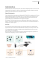
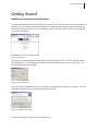
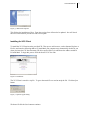
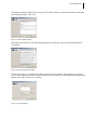
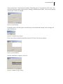
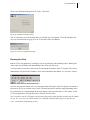
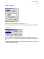
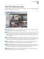
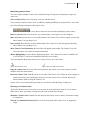
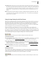
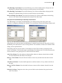
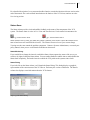
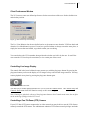
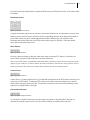
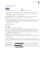
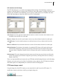
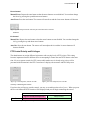
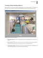
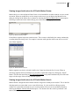
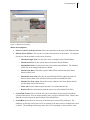
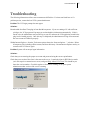
Video Capture System
User Manual
Version 5.1
Introduction _________________________________________________________________ 1
System Requirements ______________________________________________________________ 1
Getting Started _______________________________________________________________ 2
Installing the Java Runtime Environment _____________________________________________ 2
Installing the Client _______________________________________________________________ 3
Logging In _______________________________________________________________________ 8
The VCS Client Interface ______________________________________________________ 9
The Image Viewing Area __________________________________________________________ 10
Analytic Views
12
Saving the Image Viewing Area with View Schemes____________________________________ 13
Status Alarm ____________________________________________________________________ 15
Viewing Live Images _________________________________________________________ 16
Entering Live Mode and Client Preferences __________________________________________ 16
Controlling Live Image Display ____________________________________________________ 17
Controlling a Pan-Tilt-Zoom (PTZ) Camera__________________________________________ 17
PTZ Camera Image control________________________________________________________ 20
PTZ Control Priority and Privileges_________________________________________________ 21
Reviewing Archived Images____________________________________________________ 22
Viewing Images Archived on the VCS with Time and Piece Review_______________________ 22
Using the Time Review Interface ___________________________________________________ 24
The Time Review Timeline ________________________________________________________ 25
Viewing Local Images with JPEG Review ____________________________________________ 26
JPEG Review Features: Exporting Images and Saving as MPEG ________________________ 27
Recording on Motion with Motion Windows__________________________________________ 29
Viewing Images Archived on the VCS with Motion Review _____________________________ 30
Viewing Images Archived on the VCS with Motion Search _____________________________ 31
Motion Alarming ____________________________________________________________ 33
Printing & Saving Images _____________________________________________________ 34
Troubleshooting _____________________________________________________________ 35
Frequently Asked Questions ___________________________________________________ 36
Appendix A: Main Menu Command Listing ________________________________________ i
Appendix B: Glossary of Terms and Abbreviations __________________________________ iv
Appendix C: Quick Reference Card _______________________________________________v
VCS User Manual
1
Introduction
Welcome to the VCS (Video Capture System.) This manual is designed to provide an overview of VCS
client operation for the typical user. For more in-depth information regarding configuration and other
technical issues, please consult the VCS Administrator’s Manual.
System Requirements
Users running a Microsoft operating system (Windows 98/NT/2000/XP/Vista) should run the VCS client
application through the shortcut on the desktop. The VCS Client software can be installed on your PC
with the CD provided with your system. Users with another operating system should run the client
application through any web-enabled browser that supports Java applets.
PC performance is directly related to the processor speed/memory and the number of cameras being
displayed. It is likely that for displaying 16 or more cameras that a PC with 512 MB of RAM and a 1.2
GHz processor would be required.
Overview
The VCS operates with two separate networks. The video cameras transmit over a dedicated Video
network to allow full use of the network bandwidth without interfering with existing LAN traffic. The
VCS is then attached to your company’s existing network, enabling authorized viewers access, and
control, from the LAN, or the Internet.
Please ensure that your VCS network has been properly installed and configured by a qualified VCS
technician before attempting to connect to it with the VCS client.
Figure 1: VCS network overview
VCS User Manual
2
Getting Started
Installing the Java Runtime Environment
To install Java Runtime Environment insert the provided CD. Then open a web browser, such as Internet
Explorer or Firefox, and enter the following address E:\install.html your computer may automatically do
this for you when you insert the CD. Note that many CD drives are the D drive in which case the address
would be D:\install.html
Figure 2: install.html
The next step is downloading the Java Runtime Environment from the CD. To do this, click the Install
Java Runtime link. If any dialogs pop up asking if you want to Run, Save or Cancel, choose Run. The
file should then begin to download.
Figure 3: file downloading
Once the file has downloaded select the Typical Setup radio button and click the Accept button. This will
begin the installation of the Java Runtime Environment, or JRE.
Figure 4: JRE license agreement
After the installation is complete click the Finish button.
VCS User Manual
3
Figure 5: JRE install complete
This finishes the installation of Java. From time to time Java will need to be updated. Java will check
this on its own and alert you when it finds a new update.
Installing the VCS Client
To install the VCS Client insert the provided CD. Then open a web browser, such as Internet Explorer or
Firefox, and enter the following address E:\install.html your computer may automatically do this for you
when you insert the CD. Note that many CD drives are the D drive in which case the address would be
D:\install.html To begin this process click the Install VCS Client link.
Figure 6: install.html
The VCS Client is stored in a zip file. To get to the actual file we need to unzip the file. Click the Open
button.
Figure 7: open the zip file dialog
We then will click the Save button to continue.
VCS User Manual
4
Figure 8: save the install jar dialog
Select a place on the computer to save the Install file. The desktop is a good place because it will be easy
to locate and because we can delete the file after the installation.
Figure 9: save as dialog
Then locate the vcs_client_install.jar file that we just saved and double click on it to launch the
installation application.
Figure 10: VCS Client install jar
Click the Next button when the application loads.
Figure 11: install welcome screen
VCS User Manual
5
This dialog reminds you that in order to run the VCS Client software you need to have the Java Runtime
Environment installed. Click Next.
Figure 12: JRE reminder dialog
Read and accept the terms of the licensing agreement by clicking the Accept radio button and then the
Next button.
Figure 13: Acuity-VCT license dialog
Click the check box if you would like a shortcut created on your desktop. Select whether you want all
users of this computer or only the current user to have access to the VCS Client application with the radio
buttons to the right. Click Next to continue.
Figure 14: shortcut dialog
VCS User Manual
6
Choose a path for the VCS Client to be installed. The default path is C:\Program Files\VCS Client. You
can select an alternate path by typing it out or selecting it with the browse feature. Once you are satisfied
with the path, click the Next button.
Figure 15: file path dialog
If the path you have selected requires a new directory to be created (and it usually will) a message will
appear alerting you.
Figure 16: created directory message
We are now ready to install the actual files for the VCS Client. Click Next to continue.
Figure 17: file install dialog
Once the installation is complete, click Next.
Figure 18: installation progress dialog
VCS User Manual
We are now finished installing the VCS Client. Click Done.
Figure 19: installation complete dialog
The VCS will alert you to the fact that there is no default server configured. Click OK and add a new
server as described in the Logging In to the VCS section of the User Manual.
Figure 20: no servers configured message
Running the Client
Run the VCS Client program by locating the icon on your desktop and launching it there. Running the
client in this way eliminates the downloading of the client from the server.
You may run the client from a web browser by entering the IP address of the VCS system. The system
administrator will provide the IP address. Once entered, bookmark the address as a “Favorite” website.
Figure 21: Enter the server IP into the Browser
Once the web page has loaded, the VCS client application will begin to load. The display will remain in
this state for five to ten seconds as the Viewer is started (this process may take longer depending on the
PC and network). It is important that the browser display not be closed because it is the “parent” of the
VCS client application. Closing the browser will also close the client.
Note: In order to run the VCS Applet, the Java Run-Time plug-in from Sun Microsystems must be loaded
on your PC. If it is not, you will be asked if you would like to download the plug-in. If this does not
occur, consult the troubleshooting section.
7
VCS User Manual
8
Logging In to the VCS
Figure 22: The Login Window.
Once the Viewer is running, the Login Screen will appear (Figure 22).
Complete the User Name and Password fields and select OK. Please note that user names and passwords
are case-sensitive. If you continue to experience problems, consult the troubleshooting section at the end
of this document.
Figure 23: Enter the server IP into the Browser
If your site has multiple VCS systems, you can select a different VCS IP address by clicking on the
Choose different server button. Using this dialog window you can also add and remove servers from the
list.
Add a Server: Click the Add button then fill out the fields and click the Save button. The new server will
now be available in the list of servers.
Remove a Server: Select a server from the list and click the Remove button.
VCS User Manual
9
The VCS Client Interface
When successfully logged in, the VCS client screen with a menu bar, and a tool bar will appear. Below is
the VCS Client interface for the Live View.
Figure 24: Live View Interface
Main Menu Bar: Almost every command available in the client can be accessed from the menu bar.
See the reference section for a brief description of each item.
Toolbar: The toolbar provides easy access to the most commonly used features in the client. There
are currently two toolbars available. The General Toolbar has the mode changing commands along
with save and print, the View Editing Toolbar has all the commands for modifying Camera Views
and View Schemes.
Camera and Review Control Area: This portion of the interface displays controls specific to a
selected camera. Pictured above are the controls for a PTZ camera. When reviewing stored images or
alarms this area displays different recording segments identified by the time they occurred.
Image Viewing Area: All images during any type of review are displayed in this portion of the
interface. More details are provided about this area in a dedicated section below.
Playback Control: Buttons for manipulating image playback are available in this portion of the
interface. Each mode has distinct controls, but some elements are common to multiple modes. See the
description of each review mode to learn how to use the corresponding controls.
Status Alarm: This interface element is an indicator of the status of every attached camera to the
VCS Server. Read more about the Status Alarm on page 15.
VCS User Manual
10
The Image Viewing Area
The Image Viewing Area displays camera images to the user in both Live and Time-Based viewing. The
Image Viewing area is highly customizable. Each image from a camera, called a “Camera View,” can be
configured to convey the exact information you desire.
Figure 25: Add View toolbar button
Figure 25a: Edit View toolbar button
Editing Views
Add a Camera View: Click on the Add View toolbar button, or right click and select the Add View menu
option. This will display the Edit View Information dialog where you can choose what the new
Camera View will display.
Edit a Camera View: First, select the Camera View you would like to edit by left clicking on it. Then,
either press the Edit View toolbar button, or right click on the Camera View and choose the Edit View
menu option.
Using the Edit View Information dialog, you can customize the Camera View in three ways.
Figure 26: The Edit View Information dialog
Choose a Camera: Use the scroll area to select a camera for the Camera View to display.
Show Text: To display the camera time and name on the picture click the check box next to the “Display
camera text on picture” label.
Highlight View: Checking this box will cause the view to have a yellow border around it when it is
recording, and motion highlighting is enabled. When a camera is set to record on motion this feature
is meant to emphasize this view panel over the others.
Always Prepend Timestamp: This feature adds a timestamp to the beginning of the camera text.
Choose Multiple Cameras: You can have the Camera View cycle between images from different
cameras. To do so you must select multiple cameras from the list by holding down the Control key
while clicking. The Camera View will cycle between the selected cameras, pausing the number of
seconds specified in the Camera cycle rate field.
VCS User Manual
11
Manipulating Camera Views
You can configure multiple Camera Views within the Image Viewing Area to display the images you
want to see.
Select a Camera View: Left-click on the view once with the mouse.
Once you have selected a Camera View, in addition to adding and editing as explained above, you can do
any of the following commands to the Camera View.
Figure 27: The Delete, Move to Front, Move to Back, Show Info and Motion Highlighting toolbar buttons.
Delete a Camera View: Press the Delete View toolbar button. The Camera View will disappear.
Move to Front: Press the Move to Front toolbar button. This Camera View will now appear on top of any
other Camera View you drag it over.
Move to Back: Press the Move to Back toolbar button. This Camera View will now appear behind any
other Camera View you drag it over.
Show Camera View Information: Press the Show Info button in the toolbar. The Camera Views will
now either show, or not show the camera information.
Motion Highlighting: Press the Motion Highlighting button. The Camera Views that are enabled to do
so will now have a yellow box around them when they are recording.
You can manipulate the position and size of a Camera View by use of the mouse.
Figure 28: The move cursor
Figure 28a: One of the resize cursors
Drag the Camera View: Press the mouse down and move the Camera View to the location you want,
and then release the mouse button.
Resize the Camera View: Hold the cursor over an edge of the Camera View. When the cursor changes to
a double arrow line, press and drag the mouse to resize the Camera View as desired. Release the
mouse button to finish resizing the Camera View.
Camera Views can overlap and be placed however you choose within the Image viewing area.
Zooming in on a Camera View
At any time during a time or live review, you can zoom in on any particular Camera View you choose.
When you are done, your Image Viewing area will return to the previous display.
Maximize a Camera View: Double click the mouse on the Camera View to make it fill the entire Image
Viewing Area.
Zoom in on a Maximized Camera View: Left click on a portion of the Camera View to magnify the
image.
VCS User Manual
12
Return to Normal View: Double click the mouse on the Camera View to return to the previous Image
Viewing Area arrangement.
Analytic Views
One of the most exciting features of the VCS is the analytics it is capable of performing. This started as
simply motion detection, but as the VCS progresses and continues more features are being added. These
viewing modes can be accessed by right clicking on any camera view.
Figure 29: Object Tracking View in action
Motion View: Motion view lets the user see what the VCS detects as motion. Using this view causes
detected motion to appear as red and green pixels. The red pixels are parts of the image that have a
lot of motion in a neighborhood, the green pixels are either at the edges of the red sections or motion
with few neighboring motion pixels.
Object Tracking View: The Object Tracking view takes the information from the Motion View and
groups the red motion pixels into objects and puts a box around each of these objects. As each of
these objects moves around the view the VCS keeps the same box around each object.
Object Detection View: This view puts a box around objects in much the same way as the object
tracking view, but it does this based on what has changed in the background between the first image
and now. This is designed to detect things taken or left in the background, for example and
unattended bag.
B/W View: This converts the images to black and white which is the first step in Motion Detection.
VCS User Manual
13
Noise Filter View: Often times noise in the image from the camera and repetitive motion such as trees in
the wind can cause motion detection systems to give false positives. But the VCS’s Motion Detection
learns what kind of noise and repetitive motion is normal for a camera and filters this out. This view
shows this filter. The greater the noise or often the motion the closer to white that part of the view
will be.
Delta View: Delta View shows what the VCS detects as different from the last picture that it took. This
view and the Noise Filter go together to make the Motion View. This is the best way to understand
what the VCS sees as motion.
Saving the Image Viewing Area with View Schemes
When you have arranged the Image Viewing Area to display the Camera Views you desire, you can save
the positions of the Camera Views using a View Scheme. A View Scheme allows you to quickly recall
the positions, and contents of all the Camera Views previously defined in the Image Viewing Area,
simply by choosing an item from a list. View Schemes are stored on the VCS server, so no matter where
you are accessing your VCS, you can recall your View Schemes instantly.
Saving View Schemes works within any live or time review. When doing a review, loading a view
scheme will rearrange the Image Viewing Area without modifying any of the other settings in the review.
For example, if you were reviewing the previous fifteen minutes, loading a View Scheme would not cause
the time range to change. If you are not in a review, and load a View Scheme, the program will enter Live
View, with the Image Viewing Area arranged according to the View Scheme you chose.
Figure 30: The Save View Scheme, Open View Scheme, and Delete View Scheme toolbar buttons.
View Scheme Commands
Save a View Scheme: When the Image Viewing Area is as you would like it, press the Save View Scheme
toolbar button or select the View-Scheme: Save Scheme, and enter the name in the dialog box.
Load a View Scheme: Press the Open View Scheme toolbar button, and select the view scheme you
would like to load from the dialog box. Alternatively, you can use the View-Scheme: Load Scheme
submenu and select the View Scheme directly from there.
Delete a View Scheme: Press the Delete View Scheme toolbar button or select View-Scheme: Delete
Scheme and choose the view scheme to delete from the dialog box.
Rotating View Schemes
The VCS client is also capable of cycling between view schemes, much in the same way you can have a
Camera View cycle between images from different cameras. To access this feature you can create, load,
and delete Rotating View Schemes just like you did with ordinary View Schemes.
Figure 31: The Add Rotating View Scheme, Edit Rotating View Scheme, and Delete Rotating View Scheme toolbar
buttons.
VCS User Manual
14
Add a Rotating View Scheme: Press the Add Rotating View Scheme toolbar button to display the Add
Rotating View Scheme Dialog. See the next section for how to use the dialog.
Edit a Rotating View Scheme: Press the Edit Rotating View Scheme toolbar button to display the Edit
Rotating View Scheme Dialog. See the next section for how to use the dialog.
Delete a Rotating View Scheme: Press the Delete Rotating View Scheme toolbar button. In the dialog,
choose a view scheme from the drop down box and press the Okay button.
Using the Add and Edit Dialogs for Rotating View Schemes
The Add Rotating View Scheme and Edit Rotating View Scheme dialogs share many of the same
elements for configuring a Rotating View Scheme. The only difference between the dialogs is that the add
Figure 32: The Add Rotating View Scheme Dialog and the Edit Rotating View Scheme Dialog
dialog allows you to enter the name of the Rotating View Scheme whereas the edit dialog has you choose
the Rotating View Scheme from a list of existing schemes. The remainder of features are common to both
dialogs, and are explained below.
In the dialog, there are two areas where View Schemes are listed. The Available area displays all the
saved View Schemes. The list on the right is your Rotating View Scheme; the VCS client will traverse the
list one scheme at a time, pausing the Cycle Rate between each scheme.
Add a View Scheme: Press the right arrow button and the scheme or schemes selected in the available
list will be added to the end of the list on the right.
Remove a View Scheme: Press the left arrow button to remove any selected items from the list on the
right.
Add All View Schemes: Press the double right arrow to add one instance of every scheme to the list on
the right.
Remove All View Schemes: Press the double left arrow to remove all the schemes from the list on the
right
Edit the Cycle Rate: Change the value in the cycle rate field to set the duration of the pause between
each View Scheme.
VCS User Manual
15
For a detailed description of every menu and toolbar function, consult the function reference section at the
end of the manual. For a task-oriented introduction to the features of the VCS client, continue on to the
live viewing section.
Status Alarm
The Status Alarm provides visual and audible feedback on the status of the components of the VCS
system. The Status Alarm is active in Live View and Time Reviews. Under normal circumstances the
Figure 33: Inactive Status Alarm
Figure 33a: Activated Status Alarm
Status Alarm will be a silent, gray alarm bell. When a problem occurs with a Camera the alarm bell will
turn red and a tone will emit from the client PC. The alarm will turn red even if your current Image
Viewing area does not contain the problem component. Contact a Systems Administrator, or consult your
policy manual, when you see a red alarm bell and hear an alarm tone.
Status Monitoring.
If you would like to change the interval at which the Status Alarm requests the status of the server you
can do so by right-clicking the Status Alarm. You can enable/disable the audible alarm, enable/disable the
Status alarm completely, and set the interval at which the VCS performs the systems status check.
Status Dialog
If you left-click on the Status Alarm, it will launch the Status Dialog. This dialog displays a graphical
representation of the current status of the VCS Server. Each entry has a color-coded status. The Details
column also displays some information about the VCS element.
Figure 34: The Status Dialog
VCS User Manual
16
Viewing Live Images
The VCS client is designed to show the user images from any camera at any time. An important part of
monitoring any facility is the ability to view events as they unfold. The Live mode allows remote
monitoring of any camera attached to the VCS server. The user can display the images from multiple
cameras in many different ways to ensure that the user sees important events live.
Entering Live Mode
There are three ways to enter live mode when the program first begins.
Figure 35: The Customized Live dialog
•
One option is to use the Monitor: Customized Live menu option. This will prompt you with a dialog,
which allows you to choose how many cameras to display at once.
Figure 36: The Load View Scheme toolbar button
•
Another option is to load a view scheme from the View-Scheme menu, or by pressing the Load View
Scheme button on the toolbar. This will only work if the client is not currently in a time or jpeg based
review. For more details on loading view schemes, please see the view scheme section.
Figure 37: The Live Mode toolbar button
•
A third option is clicking on the Live Viewing button in the toolbar. This will launch the live view
with either the last view scheme or a default scheme selected from the Client Preferences Window.
After choosing the method to enter live mode the program will present you with the live viewing
interface.
Figure 38: The live viewing interface
VCS User Manual
17
Client Preferences Window
The VCS can save some user defined preferences for the convenience of the user. Such as default view
and window position.
Figure 39: The Client Preferences Dialog
The Live View Behavior lets the user define how he or she wants to react when the VCS firsts loads and
when the Live Mode button is pressed. It can be a specified scheme to always start at the same place, or
simply the last one that was loaded, to get back to what you were doing.
You can also have the VCS remember what position the window was left in by the user. Is used if the
user wants the VCS to always be maximized, or in a certain part of the screen.
Controlling Live Image Display
The control disk in the lower left-hand corner presents you with the play/pause button. By pressing the
play/pause button you freeze the display of live images to keep a desired still image onscreen. You may
resume playback at any time by pressing the play/pause button again.
Figure 40: The live control disk
The other way to control playback within live view is to use the Controls menu. The Controls: Play and
Controls: Pause menu items will function exactly as their names suggest.
Note: Pausing live playback, with use of the play/pause button or the Controls menu items, has no effect
on the archiving of images on the VCS server.
Controlling a Pan-Tilt-Zoom (PTZ) Camera
If your VCS has a PTZ camera connected to its video network you may be able to use the VCS client to
remotely control the PTZ camera. The administrator authorizes PTZ camera control privileges and rank.
VCS User Manual
18
If you do not have the authorization to control the PTZ camera, the PTZ portion of the VCS client will not
be enabled.
Directional Control
Figure 41: Directional Controls
Using the directional control the user can move in the pan or tilt direction. If a horizontal or vertical arrow
button is pressed, the PTZ camera will move in the corresponding direction. If an angled arrow button is
pressed, the camera will move in both appropriate directions. Alternatively, you can also use the
horizontal and vertical slider bars to move the camera in the respective direction. The Home button
moves the camera to the home preset.
Zoom Control
Figure 42: Zoom Controls
Press the right arrow button, or drag the slider to the right, to zoom the PTZ camera in. Press the left
arrow button, or drag the slider to the left to zoom the camera out.
Note: If your PTZ camera is an absolute camera the sliders will always reflect the current position of the
camera. If your camera is a relative camera, the sliders will always return to the center position, but can
still be used to move the camera in a relative direction from the current camera position.
Control Travel
Figure 43: Travel Controls
Control Travel is a setting internal to the VCS client that controls how far the PTZ camera will travel with
each press of a PTZ button. To make the PTZ camera travel further with each command, press the left
arrow button, or drag the slider to the left. To make the camera travel less with each command, press the
right arrow or drag the slider to the right.
Camera Speed Control
Figure 44: Camera Speed Controls
To increase the speed the camera pans press the right arrow button or drag the slider to the right. To
decrease the speed the camera moves, press the left arrow button or drag the slider to the left.
VCS User Manual
19
PTZ Preset Location Controls
Figure 45: PTZ Preset Location Controls
Figure 45a: Delete Preset button
To return to commonly viewed PTZ locations you can set up presets with the preset location controls.
Save Preset: When the camera is in a position you would like to be able to return to quickly, press the
floppy disk icon and enter a name for this new preset.
Move To Preset: Select a preset from the drop down box. The camera will move to that location.
Delete a Preset: Select the preset from the combo box, and then press the delete icon.
Set a Preset as Home: When the camera is in the position you would like to call “home”, press the home
button in the Preset Location Controls. Once this has been done, you can quickly return to this
position from the Directional Controls.
PTZ Preset Path Controls
Figure 46: PTZ Preset Path Controls and On/Off button
After you have defined multiple PTZ Presets using the Preset Location Controls, you can cycle the PTZ
camera between various presets. Within the PTZ Controls you can select PTZ paths to start and stop.
Once started, a PTZ path will run on the VCS server until it is told to stop. Even if you log out of your
VCS client the PTZ path will continue to run.
Start a Path: Select a path from the drop down box and press the On/Off button.
Stop a Path: Press the On/Off button; the currently running path need not be displayed in the drop down
box for this to work.
To create new PTZ Paths and exit existing ones you can access the appropriate dialogs using the main
menu bar. To access these menu items be sure to have the appropriate PTZ camera selected in the viewing
area.
Create a PTZ Path: Use the Controls: Create PTZ Path menu item to display the create PTZ Path dialog.
Edit a PTZ Path: Use the Controls: Edit PTZ Path menu item to display the edit PTZ Path dialog.
Delete a PTZ Path: Use the Controls: Delete PTZ Path menu item to display the delete PTZ Path dialog.
VCS User Manual
20
PTZ Path Add and Edit Dialogs
The PTZ Path dialogs are very similar to the Rotating Scheme dialogs. The Path dialogs contain two
columns, in the left column is a listing of the PTZ Presets, in the right column is a listing of all the presets
added to your PTZ Path. In the Add dialog you must specify a name for the new PTZ Path in the Name
field, in the edit dialog you choose the name from a list of existing Paths.
Figure 47: Add PTZ Path
Figure 47a: Edit PTZ Path
Add a Preset: Press the right arrow button and the scheme or schemes selected in the available list will
be added to the end of the list on the right.
Remove a Preset: Press the left arrow button to remove any selected items from the list on the right.
Add All Presets: Press the double right arrow to add one instance of every scheme to the list on the
right.
Remove All Presets: Press the double left arrow to remove all the schemes from the list on the right
Edit the Duration: The duration is the number of seconds the PTZ Camera will remain at this preset
location before advancing to the next preset location. Select the PTZ preset location in the right
Program column. Change the duration value by clicking on the arrows or entering a number in the
field.
Edit the Speed: This value changes how fast the camera travels from one preset for the next. Select the
preset in the right Program column. Change the speed value by clicking on the arrows or entering a
number in the field.
There is an important difference between the way PTZ Paths and the Rotating Schemes work. In Rotating
Schemes you set the cycle rate for all the View Schemes at once, whereas in the PTZ Paths, the duration
and camera speed are set independently for each Preset in the PTZ Path program.
PTZ Camera Image control
Using the Image tab of the PTZ Controls you can control the Iris and Focus of the PTZ camera. To
modify these controls, make them visible by pressing the Image tab.
Figure 48: PTZ Image Alarm Button
VCS User Manual
21
Focus Control
Manual Focus: Depress the auto button so that the arrow buttons are not disabled. You can then change
the focus by pressing the up and down arrow buttons.
Auto Focus: Press the auto button. The camera will auto-focus and the focus arrow buttons will become
Figure 49: PTZ Image Controls with auto-focus and manual iris controls
disabled.
Iris Control
Manual Iris: Depress the auto button so that the arrow buttons are not disabled. You can then change the
iris by pressing the up and down arrow buttons.
Auto Iris: Press the auto button. The camera will auto-adjust the iris and the iris arrow buttons will
become disabled.
PTZ Control Priority and Privileges
The administrator can assign different login names with varying levels of PTZ priority. This setting
becomes important when two different users are attempting to control the same PTZ camera at the same
time. If a user requests control of a PTZ camera while another user is already using it, they will be
presented with information in the PTZ Control area. It displays the username and IP of the person
Figure 50: Override panel; cannot override.
Figure 50a: Override panel; can override
currently controlling the camera.
If you have the privilege to override control, you may, as according to the rules of Table 1. When you press
the Override button the PTZ Controls will be displayed and you can begin controlling the camera.
New User
Current User
Equal or Greater Priority Level
Lesser Priority
Can not override current user
Can override current user
Table 1: PTZ User priority override capabilities
VCS User Manual
22
Reviewing Archived Images
You can view images archived on the VCS server by a time or piece basis. If you know the specific time
over which you would like to view images, select the Time-Based option. If you know the specific piece
number (or product identification number), select the Piece-Based option. The Piece Number is simply a
general way of indicating a key, or reference, to a series of recorded images. The reference could be a
product ID, a shift number, or any other unique identifier. You can also view images archived locally
using the JPEG reviewer.
Viewing Images Archived on the VCS with Time and Piece Review
When you would like to review images on the server you can display the Time Based Review dialog by
clicking on the Time Review button, Piece Review button, or choosing the Monitor: Time Based or
Monitor: Piece Based menu options. The Time Based Review dialog has three separate areas for defining
the archived images you would like to view.
Figure 51: Time Review and Piece Review toolbar buttons
Camera Selection
There are two ways to designate the cameras to review. The first of these is to use an existing View
Scheme to arrange the cameras in the Image Viewing Area. The second is to specify which cameras you
would like to see and have the VCS client arrange them for you.
View Scheme: Click the View Scheme radio button and choose a View Scheme from the drop-down
menu. This will launch the time review with the specified View Scheme.
Manually Chose Camera(s): Click the Camera: radio button. Left-click on a camera to select it. If you
would like to select more than one camera use a Control-Left-click on each camera you would like to
select. The selected cameras will be arranged automatically when you have chosen the time span and
playback rate options.
Time Span: Time Index
There are many ways to enter the time range for the images you would like to review. You should use the
Time Index tab if you know specific times you would like to review. Or, if you know a part number or
name, you can use the piece review to retrieve the time range that the particular part was in front of a
camera. There are also some advanced features that allow you to modify the viewing range based on the
time range for a particular piece.
Figure 52: Time Index tab
VCS User Manual
23
From the Previous: Play back images recorded between the present time and the specified time interval.
You can choose minutes, hours, or days as the unit of time.
Start and End: Play back images recorded between the specified Start Time and End Time.
Time Span: Piece Index
A camera must be selected to determine a reference for the start and end times of the entered piece
number. This is important because if an event occurs at one camera three minutes ahead of another, the
camera selection could change the start and end times that are used for a specified piece number by up to
three minutes. For this reason, an individual camera must be selected to act as the reference point.
Figure 53: Time Index tab
Once the Camera and Piece Name fields are completed, the Start Time and End Time will be
automatically displayed. If the specified piece number is either incorrect or no information can be found
regarding its start and end times, an error message will be displayed.
You can send the time values for the piece to the Time Index. There you can edit the time range easily.
This is useful if, for example, you want to view the two minutes before a piece as well as the duration of
the piece.
Viewing Rate Selection
This area of the dialog allows you to configure at what base speed you would like to review the images. If
you were reviewing a long period of time, two weeks for instance, you would probably want to view
fewer frames than every recorded frame. If you are interested in a particular small segment of time you
would want to ensure that you could view every possible image in that time period.
Figure 54: View options
Once you have specified the options for your review press the OK button and the VCS client will bring up
the time review interface.
VCS User Manual
24
Using the Time Review Interface
The time review interface is much like the live interface except that there is a different playback control,
and there is a timeline at the bottom of the Image Viewing Area.
The Time Review Playback Controls
Aside from the Play/Pause button and the Status Alarm, both of which we have visited earlier, the Time
Review Playback Controls have many other functions.
Figure 55: Time Review Playback Controls
Looping Playback: Press this button to play a video clip in a continuous loop. Press the button a second
time to discontinue looping.
Figure 56: Loop Playback button
Change Playback Direction: To make the images play in reverse-time, click on the Directional Toggle.
This will cause the direction of the playback to reverse. If looping is activated the review will
continue to play from the end when it reaches the beginning. The review will play in the direction that
the green bead is resting.
Figure 57: Direction Toggle control
Skip Rate: To make time pass faster in the review, use the fast motion controls.
Press the Increase Skip Rate button to make the time pass faster. This adds a skip rate indicator to the
bottom of the view screen. The skip rate settings are 100 msec, 250 msec, 500 msec, 1 sec, 2 sec, 10
sec, 15 sec, 30 sec and 1 minute. The actual number of frames you will see depends on the number
of images being saved for the camera(s) you are reviewing, and the number of images you have
requested to review in the Time Review Interface.
Press the Decrease Skip Rate button to reduce the skip rate by one setting.
VCS User Manual
25
The current play speed is displayed on the Status bar, just below the Image Viewing Area. When you
are at any Increased Playback Speed you can return to Normal speed immediately by pressing a Slow
Motion button. To go slower than normal speed you will need to use the Skip Rate buttons.
Figure 58: Skip Rate buttons
Play Speed: By pressing the Increase Play Speed button you make the playback move more slowly. This
is done by setting a delay between images.
To make playback slower press the Increase Play Speed Button. The playback rate is visible below
the view screen. The available delay rates are 100 msec, 250 msec, 500 msec, 1 sec, 2 sec, 3 sec, 4
sec, and 5 sec.
To make playback faster press the Decrease Play Speed button. If you are in any speed slow motion
review and you would like to return to normal speed you can do so by pressing a fast motion button.
Figure 59: Play Speed buttons
Move to the Previous Frame: If the Time Review is not paused, press the pause button to pause it. Press
the Previous Frame button to move the review back a single frame.
Move to the Next Frame: If the Time Review is not paused, press the pause button to pause it. Press the
Next Frame button to move the review forward a single frame.
Figure 60: The Previous Frame button
Figure 60a: The Next Frame button
The final control in the Time Review Playback Controls is the Display Motion Data button. This will be
described in further detail in the Time Line section.
Note: The Status Alarm still displays the live status of the VCS server. It does not display the status of the server
during the time you are currently reviewing.
The Time Review Timeline
The Timeline in the Time Review both displays the current playback time and allows for various controls
during playback. The Timeline can be used to jump to a particular time in the review. You can also use it
to change the range of time you are reviewing without returning to the time dialog. The Timeline is also
used to view a motion activity graph for a camera programmed to record on software motion detection.
Figure 61: Time Review Timeline with a time bar
VCS User Manual
26
A specific time is displayed at each end of the Timeline. The review start time is to the left of the
Timeline. The review end time is to the right. As the Time Review plays the Time Indicator will move
from one end to the other in the current play direction.
Adjust the Time Range: To change the time range without returning to the dialog you can click in the
time fields at either end of the Timeline and enter a new time value for the hour or minute.
Alternatively, you can use the up and down arrows to increase or decrease the time by one unit.
Change the Time Indicator position: By clicking anywhere along the motion graph, or time bar, you
can move the current play position to that location. The Time Indicator will reflect the position
change.
Scrub the Timeline: By holding the left-clicking the mouse and holding down the button, you move the
mouse back and forth over the length of the time bar, or motion graph, and the review will display
images as you “scrub” the Time Indicator over the time bar.
Viewing Local Images with JPEG Review
Saved groups of JPEGs can be viewed using the JPEG Review mode. After selecting this mode from the
Monitor menu, or pressing the JPEG Review button, you will be presented with the JPEG Review Dialog.
Figure 62: JPEG Review toolbar button
The JPEG Review Dialog allows you to browse to any directory, and then displays a listing of all the
groups of jpegs in that directory.
Browse to a directory: Click the Browse… button. You will be presented with a file-choosing dialog.
Select the directory you want to use and click the Open button. If you do not want to browse, and
know the path to the directory, you can type it directly in the field and press the Find JPEGs button.
Figure 63: JPEG review dialog
Limit Playback: Check the Limit Playback checkbox, you can limit a long series of JPEGs to a desired
amount. Simply fill in the number of JPEGs you would like to review in the field and it will be
limited to that amount on playback. If the limit is larger than the number of JPEGs in the series, all of
the JPEGs in the series will be played.
VCS User Manual
27
Figure 64: JPEG review dialog
Show all JPEGs: If you wish to start a series of JPEGs from the middle, or wish to see a preview of any
one JPEG in the directory, you can check this box to show a listing of all the jpegs in the directory.
Once you have chosen your directory and options, a listing of JPEG groups will appear in the scroll area.
Figure 65: JPEG review dialog
There is a preview area in the left portion of the dialog. It will display the first image in the selected
image group. You may select one group of JPEGs for playback and then click the OK button to enter the
JPEG review mode.
When you enter JPEG review mode the jpegs begin to play back. You can control the playing similarly to
the time based reviews. See the instructions if you need help with the controls.
JPEG Review Features
The JPEG Review offers two additional features for dealing with locally archived images. When you are
viewing raw images exported from the VCS, you can use the JPEG Verify feature to ensure that no one
has tampered with the JPEG image. Additionally, if you would like to take the JPEGS currently in the
JPEG review and convert them into a MPEG there is a convenient way to do that as well.
Export Raw Images: Select File from the Main Menu. Select Export Raw Images. The Raw Image
Export dialog screen will appear. Select the file or directory to receive the images. Select the view
scheme or specific cameras as the source of the video. Choose every saved frame or the number of
frames per second to be exported. Lastly, select the time frame of the images by the previous number
of minutes, hours or days, or by a specifically defined time span. Select OK and a window will
appear indicating the Progress of the exporting task defined above. When the task is completed the
images will be available in the chosen directory and can be reviewed with the JPEG review tools.
VCS User Manual
28
Figure 66: Raw Image Export Dialog
Verify Exported Images: Press the Image Verify button. While the button is down, you will be notified
if any modified image is encountered during the review.
Figure 67: JPEG review dialog
Convert the Images to MPEG: Use the File: Convert to MPEG main menu option.
VCS User Manual
29
Recording on Motion with Motion Windows
When a camera is set to record on motion an administrator can set up motion windows. The windows are
blue, red or yellow. They act as filters over the image that help analyze motion in the selected area.
Figure 68: Motion Detection Setup Window
•
Motion Zone (blue): The VCS will detect motion in these areas; areas left clear will not detect
motion.
•
Hot Zone (red): The Hot zone works in the same way as a Motion Zone but allows for small or
distant objects to be protected by increasing the sensitivity of the detection zone.
•
Loitering Zone (yellow): The loitering zone will not trigger the alarm unless continuous motion
occurs within the defined area for the user defined period of time.
VCS User Manual
30
Viewing Images Archived on the VCS with Motion Review
Motion Review is a more advanced form of time review intended for use when cameras are set to record
on motion. When you would like to review images on the server you can display the Motion Review
dialog by clicking on the Motion Review button, or choosing the Monitor: Motion Review menu option.
Choosing a camera and a time window brings you to the motion history graph.
Figure 69: Motion History Graph
Each of these segments represents a motion event. These events are defined by the camera continuously
recording during the time period. For example is someone walks past the whole event will be saved as
one of these segments.
Figure 70: Motion Review Control
Motion segments can also be selected in the Review Control area from the list of events. When an
interesting segments has been identified it is possible to export these images by clicking the “Export”
button. This does the same thing as File: Export Raw Images except that it automatically fills in the time
range to be the range of the currently selected segment.
Viewing Images Archived on the VCS with Motion Search
Motion Search is designed to detect motion after the images have already been recorded. This is ideal for
detecting motion on camera that is set to record all the time. It is also useful for refining a motion
window of a camera that is already set up to record on motion. The user can access Motion Search by
choosing the Monitor: Motion Search menu option. The interface after the search is preformed is the
same as Motion Review.
VCS User Manual
31
Figure 71: Motion Search Dialog
Motion Search Options
•
Select a Camera For Motion Search: Choose the camera that is the target of the Motion Search.
•
Edit the Search Window: The current view of the selected camera is shown here. Use the paint
like tools to edit the window to reflect areas of interest.
o
Motion Rectangle Tool: Use this tool to draw a rectangle on the Search Window.
o
Motion Oval Tool: Use this tool to draw an oval on the Search Window.
o
Motion Brush Tool: Use this tool to draw a line on the Search Window. The thickness
of this line can be changed with the Line Width .
o
Motion Zone (blue): Select this to paint a Motion Zone. Motion Search will detect
motion in these areas.
o
Motion Hot Zone (red): Select this to paint a Motion Hot Zone. Motion Search will
detect motion in these areas with more sensitivity than a normal Motion Zone.
o
Motion Clear Zone (clear): Select this to paint a Motion Clear Zone. Motion Search
will not detect motion in these areas.
o
Select All: Press this button to paint the entire view with a Motion Zone.
o
Deselect All: Press this button to paint the entire view with a Motion Clear Zone.
•
Search Time Frame: Choose From the Previous to search between the present time and the
specified time interval. You can choose minutes, hours, or days as the unit of time. Choose Start
and End to search between the specified Start Time and End Time.
•
Search Rate: Select the level of accuracy with which your search will be preformed. The
advantage of choosing a more coarse level of searching is the time it takes to complete the search
is shorter. The advantage of choosing a more fine level of searching is a more accurate result.
VCS User Manual
32
Motion Alarming
Motion Alarming gives a visual and audible alert to the user when a camera senses motion. This alert
turns the Alarm Button red.
Figure 72: Alarm Button Alert
Clicking on the Alarm Button brings up the list of all alarms since the user logged on. Alarms that are
currently triggered appear in red on the review list, while alarms that have finished are in gray.
Figure 73: Alarm Control (active alarm)
Figure 73a: Alarm Control (no active alarms)
Alarm Commands
•
Live: Clicking the Live Button brings the live view of the camera selected.
•
Review: Clicking the Review Button will loop a recording of the images that caused the selected
alarm.
•
Deactivate: Clicking the Deactivate Button causes the alarms currently tripped to reset.
•
Clear List: Clicking the Clear List Button causes the list of alarms to clear, making it easier to
review new alarms.
•
Disable Alarms: Clicking the Disable Alarms Button launches the Disable Alarms Dialog
VCS User Manual
33
Figure 74: Disable Alarms Dialog
Disable Alarm Dialog
This dialog allows the user to temporarily suspend the alarming function for a selected camera.
•
Camera Alarms: Each camera currently configured by the administrator for Motion Alarming
will appear in this list.
•
Status: Shows if the currently selected camera is enabled or disabled.
•
Enable: Clicking the Enable Button enables the currently selected camera
•
Disable: Clicking the Disable Button disables the currently selected camera for the number of
minutes in the area directly above the Disable Button. The camera will automatically enable after
that many minutes have elapsed.
VCS User Manual
34
Printing & Saving Images
Printing images is a privilege granted to each user by the system administrator. A printer icon
be visible on the tool bar if this function has been granted to the user.
will
A single click of the printer icon will bring up the Print dialog box from the Windows Program. The user
determines the print criteria and clicks OK and the image is sent to the printer.
Saving images for use outside the VCS is a privilege granted to each user by the system administrator. If
this function is granted a save icon
will be visible on the tool bar.
A single click of the save icon will bring up Select Save Directory and File Tag prompt. The user then
selects a destination file to receive the saved images. The user may also select the file type in which to
store the images. They can be stored as individual pictures (.jpg) or a film clip (.mpg). Images will
stored immediately after selecting the file and clicking save. They will continue to be stored until the
save icon is clicked again.
There are two ways to review the images. The first, within the VCS software, is to click on the JPEG
Review Icon. Use of the review features is detailed on page 21. The second, outside of the VCS
software, is by going to the destination file and selecting the .jpg or .mpg.
Note: Images saved in either of these two manners will appear as “MODIFIED” if they are processed
through the JPEG reviewer and the Image Verifier.
VCS User Manual
35
Troubleshooting
The following information reflects some common user difficulties. For items not listed here or if a
problem persists, contact the local VCS system administrator.
Problem: The VCS login prompt does not appear.
Solutions:
Download the Java Run-Time plug-in from Sun Microsystems. If you are running a PC with sufficient
privileges, the VCS program will prompt you to download this information automatically. If this is
not the case, the administrator may need to log on your PC and start the VCS application to enable the
plug-in to be loaded properly. Once this step is completed, the administrator will log off account and
the user account will function properly.
Within Internet Explorer - from the Tools menu option choose the “Internet Options…” selection. Delete
all temporary files including offline content, and clear the history. Restart Internet Explorer and try to
connect to the VCS Server again.
Problem: System will not accept logon information.
Solutions:
Check that you are entering the proper user name and password using the correct capitalization.
Check that your version of the client is the same as the server. Launch the client in JPEG Review mode
(as it does require a connection to a server) and go to Help: About VCS Client. This should let you
know the version number. Check this against a client that is working, or ask your system
administrator what version of the server is running.
Figure 75: Help Dialog
VCS User Manual
36
Frequently Asked Questions
What is a View Scheme? A View Scheme an arrangement of camera views in the VCS. It organizes
and memorizes the view that you had so that you can come back to it later. These can be selected through
the View-Scheme: Load Scheme menu. A hyphen before the scheme name means that it is a shared
scheme, which means that other users can see, edit and delete it.
How do I export images from the VCS? The simplest way is to do a Motion Review on the camera you
want and selecting the video segment from the list on the left side of the screen and clicking the Export
button. When you save these images you should put them in a new folder dedicated to this exportation,
because you are going to get a ton of JPEGs.
How do I save an MPEG? Begin viewing what you want to record. Pause it, then click the Save icon in
the tool bar, it is shaped like a floppy disk, and next to the print icon. If you cannot see this icon, speak
with your system administrator about saving privileges. Then select where you want to save the images
and give this recording a name, be sure to select .mpg as they file type. You will notice that the Save icon
is now red, that means that it is recording. Unpause if you are paused, to start the images moving again.
Click the red icon again when you are done with MPEG segment to end the recording.
Appendix A: Main Menu Command Listing
i
Appendix A: Main Menu Command Listing
File
Client Preferences: Displays a dialog to change the default live view and the for the currently logged
in user.
Change Password: Displays a dialog to change the password for the currently logged in user.
Save: Starts or stops saving of images from a live or time based view.
Save as MPEG: When in a JPEG review, this command will convert the timeline of JPEGs into an
MPEG.
Export Raw Images: This exports verifiable images from a Camera. You can use this function to
export official data from the VCS.
Print: Prints the current images in the Image Viewing Area.
Log Into a VCS: Logs into a VCS server.
Log Off: Logs out of the VCS server.
Exit: Quits the VCS client.
Monitor
Customized Live: Displays a dialog where any number of live cameras can be entered and displayed
in the Image Viewing Area.
Standard Live: You can choose one of the standard camera numbers from this submenu.
Motion Review: Displays the Motion Review Dialog.
Time Review: Displays the Time Review Dialog with the Time Index tab activated.
Piece Review: Displays the Time Review Dialog with the Piece Index tab activated.
JPEG Review: Displays the JPEG Review Dialog.
Motion Search: Displays the Motion Search Dialog.
Controls
Play: Starts playback if it had been paused previously.
Pause: Stops playback if it is currently playing.
Appendix A: Main Menu Command Listing
ii
Show All Frames: Slows down playback enough to ensure that every frame with data is displayed in
the Image Viewing Area.
Next Frame: When the playback is paused, this button advances to the next frame in the timeline.
Previous Frame: When the playback is paused, this button goes back to the previous frame in the
timeline.
Add PTZ Path: Displays a dialog for adding a new PTZ Path.
Edit PTZ Path: Displays a dialog for editing an existing PTZ Path.
Delete PTZ Path: Displays a dialog, which allows you to select which PTZ Path to delete.
Loop Playback: Toggles looping of playback in a review.
Change Play Direction: Reverses the direction of playback in a review.
Camera
Add View: Adds a new camera view to the image viewing area.
Edit View: Displays a dialog to edit the selected view in the image viewing area.
Delete View: Removes the selected camera view from the image viewing area.
Move To Front: Moves the selected camera view to the front in the image viewing area.
Move Forward: Moves the selected camera view forward in the image viewing area.
Move Back: Moves the selected camera view backwards in the image viewing area.
Move To Back: Moves the selected camera view to the back of the image viewing area.
View-Scheme
Rotate Scheme: Starts or stops the rotation of the last-selected rotating scheme.
Load Scheme: Loads a view scheme into the image viewing area.
Save Scheme: Saves the current arrangement of camera views in the image viewing area.
Delete Scheme: Displays a dialog, which allows you to delete a view scheme.
Add Rotating Scheme: Displays the Add Rotating Scheme dialog, which allows you to add a new
rotating scheme.
Edit Rotating Scheme: Displays the Edit Rotating Scheme dialog, which allows you to edit an
existing rotating scheme.
iii
Show
Camera Information: Shows or hides the information on all the cameras.
Motion Window: Shows the Motion window for a given camera. If you are logged in as admin, it
also allows you to edit the motion window.
General Toolbar: Shows or hides the general toolbar.
View Editing Toolbar: Shows or hides the view editing toolbar.
Help
About VCS Client: Displays information about the VCS client including the version number.
Appendix B: Glossary of Terms and Abbreviations
iv
Appendix B: Glossary of Terms and
Abbreviations
Absolute PTZ Camera: This is a PTZ camera where the current position of the camera can be
represented with a set of coordinates. It can then move relative to those coordinates in a direction,
or move to another set of specific coordinates. Absolute cameras are typically those that have a
limited range of panning, and cannot travel 360°.
Camera: An analog video camera, which transmits video over an analog cable. By connecting cameras to
a Video Server, the analog signals can be converted to digital images and stored on a VCS.
JPEG: A file format for storing an image digitally. Many programs can view jpegs, including Internet
explorer, Safari, Word, and the VCS.
MPEG: A file format for storing a digital movie. Windows Media Player and Apple QuickTime are
capable of viewing MPEGs.
Network: Group of computers connected on a wired or wireless Ethernet network.
Network Camera: A Camera with a Video Server built into it. This type of camera can be directly
connected to the Network without running an analog signal into a Video Server.
Pan: To move a camera from left to right, or right to left, along the horizontal axis. Some cameras can
pan in a 360° circle, others can only pan a smaller arc.
PTZ: Pan-Tilt-Zoom, this denotes a camera that can move on commands sent by the VCS Client.
Relative PTZ Camera: This camera does not have an absolute set of coordinates to represent the current
camera location. Even though it is not possible for the VCS client to represent this type of
camera’s current position with the slider bars, you can still store and recall preset locations.
Server: A computer that provides services over a network to a client.
Tilt: To move a camera up or down along the vertical axis. Most cameras cannot tilt through all 360° of
the vertical axis
VCS: Video Capture System. A VCS client connects for live viewing to this server. It stores images from
multiple cameras for later reviewing.
Video Server: A device that converts analog video signals into digital images for the VCS Server to
store.
Zoom: To optically move the focal lengths of a camera lens to magnify an image.
Appendix C: Quick Reference Card
v
Appendix C: Quick Reference Card
Playback Controls
Play
Pause
Decrease Fast Motion
Increase Fast Motion
Decrease Slow Motion
Increase Slow Motion
Previous Frame
General Toolbar Buttons
Time Review
Display time dialog
Piece Review
Display piece dialog
JPEG Review
Display JPEG dialog
Motion Review
Print
Add Camera View
Edit Camera View
Delete Camera View
Motion Editing Tools
Rectangle Tool
Oval Tool
Freeform Line
Move to Front
Move to Back
Camera View Info
Motion Highlighting
Add a camera view to the
image viewing area
Edit selected camera view
Delete selected camera
view
Move selected view to the
front
Move selected view to the
back
Turn camera view info
on/off
Turn Motion Highlighting
on/off
Load View Scheme
Save current image
viewing area as a view
scheme
Load a view scheme
Delete View Scheme
Delete a view scheme
Save View Scheme
Polygon Tool
Motion Modes
Display motion review
dialog
Print Image Viewing Area
View Editing Toolbar Buttons
Next Frame
Loop Playback
Start a live view
Live View
Motion Area
Loitering Zone
Hot Zone
Empty Area
Start/Stop Scheme
Rotation
Create Rotating
Scheme
Edit Rotating Scheme
Delete Rotating Scheme
Special Features
Display Motion Data
Image Checker
Starts or stops the current
rotating scheme
Show the create rotating
scheme dialog
Show the edit rotating
scheme dialog
Show the delete rotating
scheme dialog