1
USOO8891941B2
(12) United States Patent
(10) Patent No.:
Abe et al.
(54)
US 8,891,941 B2
(45) Date of Patent:
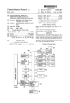
EDITING APPARATUS, EDITING METHOD,
(58)
AND EDITING PROGRAM
Nov. 18, 2014
Field of Classi?cation Search
USPC ........ .. 386/239, 248, 278, 279, 286, 353, 354
See application ?le for complete search history.
(75)
Inventors: Koichi Abe, Tokyo (JP); Shogo
Tsubouchi’ Tokyo Up)
_
(56)
References Cited
(73) Assignee: GVBB Holdings S.A.R.L., Luxembourg
(*)
U'S' PATENT DOCUMENTS
(LU)
Subject to any disclaimer, the term of this
Notice:
7,099,239 B2 * 8/2006 Ogikubo
369/3023
*
7’609’947 B2 10/2009 _Ikeda et al' """"""""" " 386/353
patent is extended or adjusted under 35
(commued)
U.S.C. 154(b) by 554 days.
(21) Appl. No.:
12/734,411
(22)
PCT Filed:
Nov. 6, 2008
(86)
PCT No..
_
§ 371 (0)0),
’
1431660 A
7/2003
1929597 A
3/2007
(Continued)
'
OTHER PUBLICATIONS
.
Apr 28 2010
'
’
2004”, Internet Citation, Nov. 1, 2004, pp. i-i3i.
Search RePOIT Dated AP? 6, 2009
_
_
_
English Translation of First Of?ce Action regarding Chinese Patent
PCT Pub. Date: May 14, 2009
(65)
Application No. 2008801152767.
English Translation of Second Of?ce Action regarding Chinese
Patent Application No. 2008801152767.
Prior Publication Data
US 2010/0254671 A1
.
EVS: “Multicam Software User’s Manual Vers10n 6.02.04 Nov.
PCT Pub. No.: WO2009/060615
(30)
CN
CN
PCT/JP2008/003220
(2) (4) Date.
(87)
FOREIGN PATENT DOCUMENTS
Oct. 7, 2010
(Continued)
Foreign Application Priority Data
P1’imary Examiner * Tat Chio
(74) Attorney, Agent, or Firm * Arent Fox LLP
()
(200601)
H.d.1d.
d..gpp
d
d..g
method for editing a moving image. An editing apparatus,
H04N 5/76
(200601)
comprises: a means for playing back a movmg image; a
G113 27/03 4
H04N 5/77
(200601)
(200601)
switching means for switching playback between a ?rst mov
ing image and a second moving image; and a means for,
H04N 9/82
H04N 5/78]
(2006 01)
(200601)
during playback of the ?rst moving image, in response to
switching playback from the ?rst moving image to the second
H04N 5/783
(2006:01)
moving image, setting a reference point at a last played back
H04N 5/765
(2006 01)
position of the ?rst movmg image. The editing apparatus
51 NOV.
Int,
7, Cl,
. . . . . . . . . . . . . . . . . . . . . . . . . . . . . . . ..
H04N 5/93
(52)
U 5 Cl
erem
isc ose
is
an
e
itin
a
aratus
an
an
e
itin
'
G1 13 27/034 (2013 01), H04N 5/772
further comprises: a controller for receiving an instruction
from a user, wherein the switching means carries out the
(201301); H04N5/76 (2013.01); H04N 9/8205
(2013.01); H04N 5/78] (2013.01); H04N 5/783
(2013.01); H04N 5/765 (2013.01)
image, in response to the controller receiving a selection of
the second moving image from the user.
'
USPC
........................................................ ..
386/278
switching from the ?rst moving image to the second moving
11 Claims, 8 Drawing Sheets
US 8,891,941 B2
Page 2
(56)
References Cited
OTHER PUBLICATIONS
U-S- PATENT DOCUMENTS
English Translation of Third Of?ce Action regarding Chinese Patent
Application No. 2008801152767.
2003/0165324 A1
9/2003 O,C0nn0r et 31‘
IPRP dated May 11, 2010 With Written Opinion regarding PCT
2005/0060755 A1
2007/0182864 A1
3/2005 Daniels
8/2007 Stoneham et al.
Appllcatlon NO~ PCT/JP2008003220
Notice of Reason for Rejection dated Jan. 15, 2013 regarding Japa
nese Patent Application No. JP2010-531659.
FOREIGN PATENT DOCUMENTS
Notice of Decision of Rejection dated Oct. 22, 2013 regarding Japa
nese Patent Application No. JP2010-531659.
EP
1266521
7/2002
Final Notice of Reasons for Rejection dated Jun. 10, 2014 regarding
JP
2002125152 A
4/2002
J
JP
200530392 A
10/2005
JP
2006222705 A
8/2006
JP
2004274627 A
9/2004
aPan
_
Pt tA
‘1 6“
l.
t.
PP “*1 1°“
_
* Clted by examlner
N
0'
JPZOIO 531659
'
'
US. Patent
Nov. 18, 2014
Sheet 2 0f8
US 8,891,941 B2
Fig. 2
HQ
134
2
Decoder
Monitor
To Transmitter
L
Input
11
Encoder
Encoder
Encoder
Decoder
v
v
A
v
A
v
A
1
271
v 2
v 26‘
Output
M
v
I
A i
1’
M
281
v a
I
Image Server
_____________________________________ ____,___________________.__J
111
#141 LAN
l
|
,
|
"‘
~
' 1
1 |
1 1
1 i
1
250
!g
260
:
'
|
i
CPU
Memory |
1
l
I
i !
i I
1 y
I
1
I
, i '
:\
| !
l
|
1
{l
1
A
I}
I
l
l 1
|__,_ ______________ _________ _ ____________________________ ___.'
}
|
'
i
I
210
V H
I
|
|_
|
220
L
1 Display 1 lButtonj
..____.___._____
Mouse
113
230
240
11‘
Jog Dial
1
l
I|
1
_______________.__._____._______._|
Keyboard
System
112
Monitor
H
135
US. Patent
Fig.3
NOV. 18, 2014
Sheet 3 0f 8
US 8,891,941 B2
US. Patent
Nov. 18, 2014
Sheet 4 0f8
US 8,891,941 B2
Fig. 4
401
,1
MOVING IMAGE
SWITCHING MEANS
t
402
a
403
2
REFERENCE POINT
SETTING MEANS
PLAYBACK POINT
SHIFTING MEANS
404
g
MOVING IMAGE
PLAYBACK
MEANS
405
406
,J
DECODING UNIT
US. Patent
Nov. 18, 2014
Sheet 5 0f8
US 8,891,941 B2
Fig. 5
START
8501
,J
PREVIEW PLAYBACK OF CLIP A
IS SWITCHING
TO CLIP B REQUESTED?
S510
_H
SETTING AND STORING IN—POINT ON
IMAGE OF CLIP A AT TIME POINT OF
SWITCHING REQUEST
l
5515
r.)
PREVIEW PLAYBACK OF CLIP B
S520
IS SWITCHING
O CLIP C REQUESTED”
$525
(I
SETTING AND STORING IN-POINT ON
IMAGE OF CLIP B AT TIME POINT OF
SWITCHING REQUEST
l
S530
r.)
PREVIEW PLAYBACK OF CLIP C
IS SWITCHING
TO CLIP A REQUESTED?
SETTING AND STORING IN-POINT ON
IMAGE OF CLIP C AT TIME POINT OF
SWITCHING REQUEST
l
8545
rI
PLAYBACK POINT IS SHIFI'ED TO CLIP A
US. Patent
Nov. 18, 2014
US 8,891,941 B2
Sheet 6 0f 8
Fig. 6
8601
r)
PLAYBACK OF CLIP A
PLAYBACK
POINT TO CLIP B
REQUESTED?
8610
f.)
PLAYBACK OF CLIP B FROM
IN-POINT
IS SHIFTING
PLAYBACK
POINT TO CLIP 0
REQUESTED?
8620
(J
PLAYBACK OF CLIP C FROM
IN-POINT
i
STOP
8325
US. Patent
Nov. 18, 2014
Sheet 7 0f8
US 8,891,941 B2
Fig. 7
H
I
131
121
/
l
l
CLIP A
IN (A)
TIME LINE 701
1
@_+
l
!
|
CLIP B
IN"“(13) !
I
L
TIME LINE 702
M 1
l
T‘
123
1133
I
I
I
l
CLIP 0
IN (0)
i
*
I
o_
N
*F
1
TIME LINE 703 i
l
V
1
TO IN (A) IN FIG. 8
134
I
134
/
IN (A)
IN (C)
US. Patent
NOV. 18, 2014
US 8,891,941 B2
Sheet 8 0f 8
Fig. 8
121
FROM 0 IN FIG. 7
CLIP A
1
TIME LINE 801
CLIP B
1
123
TIME LINE 802
CLIP 0
TIME LINE 803
134
/
|
|
|
H
TIME LINE ON DECODER 804
US 8,891,941 B2
1
2
EDITING APPARATUS, EDITING METHOD,
playing back the moving image; and a means for, during
playback of the ?rst moving image, in response to switching
playback from the ?rst moving image to the second moving
image, setting a reference point at a last played back position
of the ?rst moving image.
According to the present invention, the means for setting
sets the reference point at the last played back position of the
AND EDITING PROGRAM
This application claims the bene?t, under 35 U.S.C. §365
of International Application PCT/JP2008/003220, ?led Nov.
6, 2008, which was published in accordance with PCT Article
21(2) on May 14, 2009 in English and which claims the
bene?t of Japanese application No. 2007-289820, ?led Nov.
7, 2007.
?rst moving image that has been played back only by switch
ing from the ?rst moving image to the second moving image
using the switching means during playback of the ?rst mov
ing image. This eliminates an operation for setting the refer
ence point, and it is possible to provide an editing apparatus
TECHNICAL FIELD
allowing quick editing of a plurality of moving images. More
The present invention relates to an editing apparatus, an
over, the editing apparatus can set the reference point in the
editing method, and an editing program, and more particu
larly, to an editing apparatus, an editing method, and an
same manner even when there are more than two moving
images, allowing quick editing of the moving images.
editing program for editing a plurality of moving images
which have been recoded or are being recoded, and playing
back the edited moving images.
BACKGROUND ART
20
Further, according to the present invention, while the ?rst
and second moving image are edited, only one of the ?rst and
the second moving images is played back at one time. There
fore, it is possible to edit either of the ?rst and second moving
images while the moving image is decoded by a single
decoder unit even when the ?rst and second moving images
are encoded, and to set the reference point. Moreover, this
Conventionally, in the broadcasting ?eld, especially in a
live sport telecast and the like, to concatenate a plurality of
scenes recorded by a plurality of camcorders or to change the
duration of each of the scenes, the plurality of scenes are
also applies to the case in which there are more than two
25
moving images, and it is possible to edit each of the moving
images while the moving image is decoded by the single
played back and edited using a recording/playback device
including a recording medium allowing for a faster random
decoder unit, and to set the reference point.
access such as a hard disk device. While such a recording/
It should be noted that, the expression “during playback”
playback device including a recording medium allowing for a
faster random access is improved in convenience in compari
includes cases where a moving image is played back in a
certain speed, where a moving image is played back as a still
30
image, and where a playback of a moving image is stopped
after playing back the moving image as a still image. In
son with a video tape recorder carrying out a sequential
access, still much is left to be improved in terms of operabil
addition, the expression “moving image” includes “moving
image data”, “moving image signal”, and “clip” used in the
ity.
For improved operability, Japanese Unexamined Patent
Application Publication No. H09-233430 discloses a device
35
present speci?cation. Unless otherwise stated, the expres
for recognizing an order and duration of a series of scenes to
sions are used similarly in the claims and speci?cation of the
be played back and further editing the series of scenes, by, for
example, displaying in chronological order the series of
present application.
scenes to be played back in a bar chart having segments
re?ecting the duration of each of the scenes.
40
Patent Citation 1: Japanese Unexamined Patent Application
Publication No. H09-233430
DISCLOSURE OF INVENTION
45
Technical Problem
In a live sport telecast, for example in a live baseball game
broadcast, a controversial play or a home-run scene is often
broadcasted immediately after it occurs. In this case, it is
50
preferable that a plurality of moving images taken from a
plurality of angles are edited and broadcasted before viewers
lose interest.
In light of the abovementioned problems, an objective of
the present invention is to provide an editing apparatus, an
55
moving image; and a step of setting a reference point at a last
editing method and an editing program allowing quick edit
ing of a plurality of moving images. Another objective of the
present invention is to provide an editing apparatus, an editing
method and an editing program allowing quick playback of
such moving images.
60
played back position of the ?rst moving image in response to
the switching to the second moving image.
According to the present invention, the reference point can
be set at the last played back position of the ?rst moving
image that has been played back only by switching from the
?rst moving image to the second moving image during play
Technical Solution
In accordance with a ?rst aspect of the present invention,
there is provided an editing apparatus, comprising: a switch
ing means for switching playback between a ?rst moving
image and a second moving image; a playback means for
Further, the editing apparatus according to the present
invention may further comprise a playback point shifting
means, wherein the playback point shifting means shifts,
during playback of the second moving image, in response to
switching playback from the second moving image to the ?rst
moving image, the playback point to the reference point of the
?rst moving image from the second moving image, and the
playback means plays back the ?rst moving image from the
reference point. The playback point shifting means shifts, in
response to switching playback from the second moving
image to the ?rst moving image, the playback point to the
reference point of the ?rst moving image. Therefore, it is
possible to quickly play back the ?rst moving image from the
reference point.
In accordance with another aspect of the present invention,
there is provided an editing method, comprising: a step of
playing back a ?rst moving image; a step of switching play
back to a second moving image during playback of the ?rst
65
back of the ?rst moving image. Therefore, it is possible to
quickly set a reference point in the ?rst moving image, allow
ing quick editing. Moreover, the reference point can be set in
the same manner even when there are more than two moving
images, allowing quick editing. Further, for the same reason
US 8,891,941 B2
3
4
as described above, even when the ?rst and second moving
an editing system 10 is provided with an image server 101, a
controller 111, a keyboard 112, a mouse 113, camcorders
images are encoded, it is possible to edit each of the moving
121-123, camcorder monitors 131-133, decoder monitors
134, system monitors 135, and the like. Each of the compo
images while the moving image is decoded by the single
decoder unit, and to set the reference point.
In accordance with still another aspect of the present inven
tion, there is provided an editing program that is executable
by a computer to carry out the steps comprising: a step of
nents forming the editing system 10 is connected, using, for
example, a LAN (Local Area Network) 141 to connect the
image server 101 and the controller 111, a coaxial cable 124
to connect the image server 101 and the camcorders 121-123,
a coaxial cable 136 to connect the image server 101 and the
playing back a ?rst moving image; a step of switching play
back to a second moving image during playback of the ?rst
moving image; and a step of setting, in response to the switch
camcorder monitors 131-133, aVGA (Video GraphicsArray)
cable 138 to connect the image server 101 and the decoder
monitor 134, a VGA cable 137 to connect the controller 111
and the system monitor 135, a coaxial cable 136 to connect
the image server 101 and an output device 140, and so on.
However, the method of connection is not limited thereto.
ing to the second moving image, a reference point at a last
played back position of the ?rst moving image.
According to the present invention, it is possible to realize
an editing program having the same effects and advantages as
the invention of the method described above.
Advantageous Effects
Furthermore, the present embodiment of the editing appa
ratus according to the present invention is provided with the
According to the present invention, an objective of the
present invention is to provide an editing apparatus, an editing
method and an editing program allowing quick editing of a
image server 101 and the controller 111, as will be described
later. It should be noted that, that the image server 101 may
also be con?gured as a single unit integrating the controller
111.
20
The image server 101 encodes the moving image signal
plurality of moving images, and further provide an editing
received from the camcorders 121-123, and stores the
apparatus, an editing method and an editing program allow
ing quick playback of such moving images.
25
encoded signal as moving image data. Furthermore, the
image server 101 decodes the moving image data into the
moving image signal, and sends the moving image signal to
BRIEF DESCRIPTION OF THE DRAWINGS
the decoder monitor 134. The decoder monitor 134 displays
moving images based on the moving image signal received
FIG. 1 is a block diagram showing an overview of an
embodiment of an editing system including an editing appa
ratus according to the present invention;
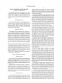
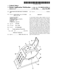
FIG. 2 is a block diagram of the embodiment of the editing
from the image server 101. The camcorder monitors 131-133
30
123. Furthermore, the image server 101 may also send the
moving image signal to, for example, the output device 140
for broadcasting.
apparatus according to the present invention;
FIG. 3 is a perspective view of a controller;
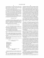
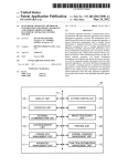
FIG. 4 is a functional con?guration diagram of the embodi
ment of the editing apparatus according to the present inven
35
The controller 111 sends and receives via the image server
101 and the LAN 141, and displays a user interface on the
display screen (shown in FIG. 3), based on a signal sent from
tion;
the image server 101 and a user input. Furthermore, the con
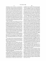
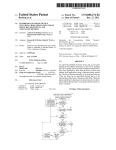
FIG. 5 is a ?ow chart illustrating a ?rst part of an embodi
ment of an editing method according to the present invention;
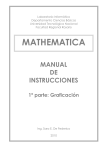
FIG. 6 is a ?ow chart illustrating a second part of the
embodiment of the editing method according to the present
40
invention;
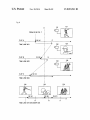
FIG. 7 is a schematic diagram illustrating a ?rst part of the
FIG. 8 is a schematic diagram illustrating a second part of
the editing method.
45
Image server
Controller
Hard disk drive
CPU
single target subject from different angles or using different
50
lenses having different ?eld angles, and may include a normal
camcorder and a camcorder capable of high-speed photo
graphing. Furthermore, the camcorders 121-123 may take
images of different target subjects.
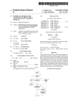
FIG. 2 is a block diagram of the embodiment of an editing
55
281 Memory
341 Decoder
BEST MODE FOR CARRYING OUT THE
INVENTION
The camcorders 121-123 capture images of a target subject
and output the images as a moving image signal, and send the
moving image signal to the image server 101 via the coaxial
cable 124. The camcorders 121-123 may take images of a
EXPLANATION OF THE NUMERAL
REFERENCES
10 Editing system
100 Editing apparatus
troller 111 converts the user input that has been inputted by
the mouse 113, by the keyboard 112 or by the controller 111
itself into a signal, and sends the signal to the image server
101. Still further, the controller 111 sends the signal for
displaying the user interface to the system monitor 135 via the
VGA cable 137.
editing method; and
101
111
261
271
display the moving images captured by the camcorders 121
60
apparatus according to the present invention. As shown in
FIGS. 1 and 2, an editing apparatus 100 is provided with the
image server 101, the controller 111, the keyboard 112, the
mouse 113, the system monitor 135, the decoder monitor 134,
and the like. Although the image server 101 and the controller
111 are constructed separately, it should be noted that the
image server 101 and the controller 111 may be constructed
as a single unit.
Preferred embodiments of the present invention will be
described below with reference to the accompanying draw
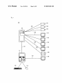
The image server 101 is provided with an input 201, encod
ings.
FIG. 1 is a block diagram showing an overview of an
editing system including an embodiment of an editing appa
ratus according to the present invention. As shown in FIG. 1,
65
ers 211-213, a decoder 241, an output 251, a hard disk drive
261, a CPU 271, and a memory 281, which are communicably
connected to each other through a bus.
The input 201 receives the moving image signal from the
camcorders 121-123. The moving image signal may be, for
US 8,891,941 B2
5
6
example, a moving image signal stored on a video recording
The controller management section 291 is provided with a
CPU 250 and a memory 260. The controller management
section 291 sends and receives a signal to and from the image
server 101, sends a signal for displaying the user interface to
apparatus such as a video tape recorder (VTR) or an optical
disk device. The input 201 may receive moving image data
that has been externally encoded.
The encoders 211-213 encode the moving image signal
sent from the input 201 into encoded moving image data that
includes time information. Furthermore, the encoders 211
213 may also read out and encode a moving image signal
the display 210 and the system monitor 135, and sends input
data or a request command received as an input from the
button group 220, the T-bar 230, the jog dial 240, the key
board 112, and the mouse 113 to the image server 101.
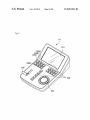
FIG. 3 is a perspective view of the controller 111. As shown
stored on the hard disk drive 261.
The decoder 241 reads out and decodes the encoded mov
in FIGS. 3 and 2, the controller 111 is provided with the
display 210 on an upper portion of the controller 111, the
ing image data from the hard disk drive 261, and sends the
moving image signal to the output 251 or the like. Further
button group 220 arranged in arrays in a central area below the
display 210, the T-bar 230 disposed in a lower left portion
below the display 210 and operated by the user by shifting the
more, the decoder 241 may directly receive and decode the
encoded image data supplied to the input 20.
The output 251 receives the moving image signal that has
been decoded from the decoder 241, and outputs the signal to
bar to and fro to tilt, and the jog dial 240 disposed in a lower
right portion below the display 210 and operated by the user
by rotating the dial horizontally.
the decoder monitor 134 and the transmitter 140. The output
The display 210 displays the user interface corresponding
251 outputs the moving image signal in a format compliant
to the signal and user input sent from the image server 101.
with a device that is connected to the output 251. For example,
a VGA signal is outputted from the output 251 to the decoder
20
monitor 134, and an HD-SDI signal is outputted from the
output 251 to the transmitter 140. Further, the output 251 may
play screen and a position at which the user touched the
display screen, and it is possible to input data or request
commands through the touch panel.
receive and output the moving image signal that has been read
from the input 201 and the hard disk drive 261, or the encoded
25
moving image data from the input 201 and the hard disk drive
261, or may receive the encoded moving image data from the
encoders 211-213 and output the received encoded moving
30
C as will be described later) corresponding to the selection
button that has been pressed is selected. The selected moving
image data is decoded by the decoder unit in the playback
35
The T-bar 230 sends a signal to the image server 101, the
signal corresponding to the degree of the angle of the T-bar
230 that has been shifted by the user to or fro to tilt, and the
40
playback speed of moving images to be played back, that is to
say, the moving images that are to be displayed on the decoder
monitor 134, can be adjusted in accordance with the degree of
the angle of the T-bar 230.
The jog dial 240 sends a signal to the image server 101, the
signal corresponding to a rotation speed of the jog dial 240
horizontally rotated by the user operation. For example, rotat
ing the jog dial 240 faster increases the playback speed of the
moving images (the playback speed of the moving images to
on.
be displayed on the decoder monitor 134), and stopping the
The memory 281 stores programs that have been read out
50
rotation stops the playback of the moving images. Further
55
more, if the jog dial 240 is rotated in the clockwise direction,
playback is in the forward direction, and if the jog dial 240 is
rotated in the counterclockwise direction, playback is in the
backward direction.
It should be noted that, that functions of the controller 111
include applications for editing or playing back moving
image data in response to an input and an output from the
controller 111, and the OS for controlling the devices con
nected to the bus, and so on. Furthermore, the memory 281
may store moving image signals and moving image data from
operation, and displayed on the decoder monitor 134 or trans
mitted externally.
281, and carries out various processing. Examples of the
programs executed by the CPU 271 include applications for
editing or playing back moving image data, an OS (Operating
System) for controlling devices connected to the bus, and so
from the hard disk drive 261. Examples of the programs
121-123 to play back the selected image data. By the user
pressing any of the selection buttons 220A-220C, one of the
pieces of the moving image data (for example, clip A to clip
executed by the CPU 271 and the encoded moving image data
sent from the encoders 211-213. Furthermore, the hard disk
drive 261 may directly store the moving signal sent from the
input 201. The hard disk drive 261 may be provided within the
image server 101, externally to the image server 101, or both.
Still further, while the present embodiment of the present
invention describes the hard disk drive 261 for explanatory
purposes, any memory device, for example, such as a tape
drive, an optical disk drive, a large volume memory, or any
combination thereof may be used other than a hard disk drive,
as long as such a device is capable of storing moving image
data or a moving image signal.
The CPU 271 reads out programs stored in the memory
The button group 220 sends a signal to the image server 101
in response to the user pressing the button group 220. For
example, selection buttons 220A-220C are buttons for select
ing pieces of image data respectively taken by the camcorders
image data.
The hard disk drive 261 stores programs that are to be
Furthermore, the display 210 may be a touch panel display
capable of detecting touch operations by the user to the dis
the devices connected to the bus.
The decoder monitor 134 is connected to the output 251,
may also be carried out by way of a graphical user interface
displayed on the system monitor 135 with the mouse 113 or
and displays a moving image based on the moving image
the keyboard 112. The keyboard 112, the mouse 113, and the
signal, such as a VGA signal, sent from the output 251. While
the decoder monitor 134 is used to monitor the content of the
system monitor 135 may be connected to the bus of the
60
moving image signal in preview playback or in playback for
broadcasting as will be described later, the decoder monitor
134 is not necessarily essential for the image processing
system 100.
Furthermore, the controller 111 is provided with a control
ler management section 291, a display 210, button group 220,
a T-bar 230, and ajog dial 240.
editing apparatus 100. On the other hand, if the controller 111
is provided, the keyboard 112, the mouse 113, and the system
monitor 135 are not required in the editing system 100, and
may be omitted.
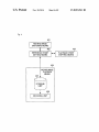
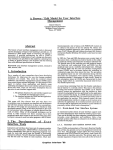
FIG. 4 is a functional con?guration diagram of an embodi
65
ment of the editing apparatus according to the present inven
tion. As shown in FIGS. 2 and 4, by cooperation between the
components shown in FIG. 2 and the programs, the editing
US 8,891,941 B2
7
8
apparatus implements a switching means 401, a reference
from center ?eld is stored as clip C. Time lines 701-703 show
point setting means 402, a playback point shifting means 403,
and a playback means 404 including a storage unit 405 and a
the time information of the clips A to C respectively as points
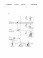
on straight lines.
decoding unit 406. With the above-mentioned means, the
CPU 271 executes: (l) a moving image editing and reference
S545 of FIG. 5 and regarding FIG. 7, the steps for setting an
In the following description regarding Step S501 to Step
in-point on each of the clips A to C are described as a part of
point setting function; and (2) a moving image playback
the editing operation. It should be noted that, the in-point is a
start point for playing back each of the clips A to C (described
later), which is one of the abovementioned reference points,
in other words, reference points (markers) set on the time
function. The functions of the editing apparatus are described
hereinafter.
(1) Moving Image Editing and Reference Point Setting
Function
information of moving image data.
The CPU 271, by using the playback means 404, reads
moving image data A stored in the storage unit 405, decodes
the moving image data A by the decoding unit 406 and plays
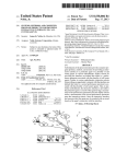
According to FIGS. 5 and 7, in Step S501, the CPU 271 ?rst
executes a preview playback of the clip A. In this step, the user
executes a variable speed playback of the clip A by manipu
lating the jog dial 240, to locate a point on the moving image
back the decoded moving image data. In response to a switch
ing request to moving image data B from the user, the CPU
271 switches the moving image data A to the moving image
data B by the switching means 401 and plays back the image
data B. In response to the switching request, the reference
point setting means 402 sets a reference point on the moving
data where an in-point will be set. The controller 111 sends a
signal to the CPU 271 in response to the manipulation of the
jog dial 240, and then the CPU 271 shifts the playback point
while the moving image data is played back. The user ?nds a
20
point H where a batter has hit a home run and then shifts the
image data A corresponding to a portion of the moving image
playback point backward to a point K where the batter has
at a time point that has been last played back. This allows an
taken a stance a short time before that.
automatic setting of a reference point only by submitting a
More speci?cally, in Step S501, the CPU 271 switches to
the clip A upon receiving the signal from the controller 11 1, in
response to the user’s input, for example, pressing the selec
switching request of moving image data, without requiring
the user to set a reference point, thus allowing quick editing.
25
tion button 220A of the controller 111 corresponding to the
clip A. In a case of reading the moving image data of the clip
A while the camcorder 121 is taking images, the CPU 271
(2) Moving Image Playback Function
The CPU 271 shifts a playback point to the reference point
on the moving image data A between the moving image data
A and the moving image data B respectively with set refer
ence points and stored in the storage unit 405, by using the
playback point shifting means 403, in response to a playback
point shifting request from the user to the moving image data
A. And then, the CPU 271, in response to a playback start
request from the user, starts playing back the moving image
data A from the playback point, in other words, the reference
reads the latest replayable moving image data in the clip A, for
30
example, a few frames to some dozens of frames before the
time point where the switching operation to the clip A was
executed. Thus, the latest moving image data requested by the
user can be quickly read. Alternatively, in a case where the
35
termined reference point only by submitting the playback
point shifting request, thus allowing quickplayback. It should
intended moving image data without erroneous operation,
since the reading of the moving image data always starts from
40
the predetermined point.
In this case, the clip A is still in recording; thus the CPU 271
reads the latest replayable moving image data of the clip A
45
be noted that, in a case where moving image data stored in the
storage unit 405 is not encoded, the decoding unit 406 is not
from the hard disk drive 261, decodes the read data by the
decoder 241, and displays the decoded data on the decoder
monitor 134. Further, the CPU 271 reads the moving image
data sequentially, backwards from the latest point to the point
H where the batter has hit a home run, in this case in accor
used, and thus not required.
dance with a rewind playback operation, in other words a
counterclockwise manipulation of the jog dial 240, and at a
FIGS. 5 and 6 are ?ow charts illustrating an embodiment of
an editing method according to the present embodiment.
FIGS. 7 and 8 are schematic diagrams illustrating an editing
camcorder 121 is not taking images, the moving image data at
a predetermined point, for example at the beginning or at the
end of the clip A, can be read. This allows the user to locate
point, by using the playback means 404. Subsequently, the
CPU 271, in response to the playback point shifting request
from the user to the moving image data B, stops playing back
the moving image data A and shifts the playback point to the
reference point on the moving image data B. Thereafter, the
CPU 271 plays back the moving image data B using the
playback means 404. This allows the playback from a prede
example, moving image data located slightly before, for
50
speed corresponding to the rotation speed of the jog dial 240,
decodes the read data by the decoder 241, and displays the
operation. The present embodiment of the editing method is
decoded data on the decoder monitor 134.
described hereinafter with an example of live broadcasting of
In Step S505, the CPU 271 determines whether a switching
request to the clip B has been made or not. More speci?cally,
the CPU 271 determines whether a switching request to
a baseball game. It should be noted that FIGS. 1 to 4 are
referenced accordingly hereinafter.
55
As shown in FIG. 7, the camcorders 121-123 are taking
images of a batter in a batter’s box simultaneously from
switch to the clip B has been made or not based on whether the
selection button 220B for the clip B has been pressed or not,
in accordance with a signal from the controller 111. If it is
different angles: in a full-length ?gure; in a close-up shot; and
determined that the switching request has been made, the
in a distant shot from center ?eld, as shown in camcorder
monitors 131-133. Moving image signals respectively sub
60
mitted from the camcorders 121-123 are encoded with time
information by encoders (211 to 213 in FIG. 2) and stored in
ing request to switch to the clip B by reiterating Step S505.
a hard disk drive 261 as collections of moving image data.
Each collection of moving image data is referred to as a
“clip”. In the present example, the shot of the full-length
?gure of the batter is stored as clip A; the close-up shot of the
batter is stored as clip B; and the distance shot of the batter
process advances to Step S510. If it is determined that the
switching request has not been made, the process returns to
Step S505. In other words, the CPU 271 waits for the switch
65
Next, in Step S510, the CPU 271 sets an in-point in(A) at
the point K on the clip A in response to the switching request
to switch to the clip B and stores the position of the in-point
in(A), in other words the point K, to the memory 281. More
US 8,891,941 B2
10
speci?cally, the point K on the clip A is time information
corresponding to the last moving image data played back on
the clip Abefore switching to the clip B. The time information
Step S520. In other words, the CPU 271 waits for the switch
ing request to switch to the clip C by reiterating Step S520.
Next, in Step S525, the CPU 271 sets an in-point in(B) at
the point M on the clip B in response to the switching request
to switch to the clip C and stores the position of the in-point
in(B), in other words the point M, to the memory 281. More
speci?cally, the point M on the clip B is time information
corresponding to the last moving image data played back on
the clip B before switching to the clip C. It should be noted
is a time code, for example. In a case where an instruction or
the like is made by the controller 111, the position of the
in-point can be stored in the hard disk drive 261. The user thus
can set the in-point in(A) on the clip A by merely executing a
switching operation to switch to the clip B. This does not
require the user to set the in-point, thus allowing quick edit
ing. It should be noted that the clip A is preferably paused (in
that the setting and the storage of the in-point in(B) is similar
to that of the in-point in(A), thus providing a similar effect.
Next, in Step S530, the CPU 271 starts a preview playback
of the clip C. Upon reception of the switching request to
a still mode) before making the switching request to switch to
the clip B. By this, the in-point in(A) can be set on the still
moving image data, thus allowing the user to set the in-point
in(A) infallibly on the intended moving image data. It should
be noted that, it is also preferable that the moving image data
is paused before making a switching request to switch to the
clip C (described later) and making the playback point shift
ing request for the clip A.
Next, in Step S515, a preview playback of the clip B is
performed. Upon reception of the switching request to switch
20
to the clip B from the controller 111, the CPU 271 moves the
playback point from the point K on the clip A to a point L on
the clip B having the same time information as the point K,
and plays back the clip B from the point L. In other words, the
25
CPU 271 starts playing back the clip B from the point L on the
time line 702 having the same time information as the point K
on the time line 701 of the clip A. As described above, by
111, the playback point to a point 0, which is remote from the
point N where the batter has hit the home run. More speci?
cally, the CPU 271 reads the clip C, from the hard disk drive
261, sequentially from the moving image data having the
switching the playback point between the two points on the
clips A and B sharing the same time information, the user can
switch to the clip C from the controller 111, the CPU 271
moves the playback point from the point M on the clip B to a
point N on the clip C. In other words, the CPU 271 starts
playing back the clip C from the point N on the time line 703
for the clip C, having the same time information as the point
M on the time line 702 for the clip B. This also provides the
same effect as that in the switching of the playbackpoint from
the clip A to the clip B. The controller 111 sends a signal in
response to the user’s manipulation of the jog dial 240. The
CPU 271 shifts, in response to the signal from the controller
same time information as that of the last played back moving
30
image data on the clip B, and decodes the moving image data
?nd more easily the moving image data on the clip B tempo
by the decoder 241. The controller 111 sends a signal in
rally close to and thus closely relating to the moving image
accordance with the manipulation of the jog dial 240. The
CPU 271 then reads the moving image data sequentially, in
data at the in-point in(A) on the clip A. This allows the user to
quickly locate the intended point on the clip B.
It should be noted that a program for the editing apparatus
response to the signal from the controller 111, at a speed
35
may be con?gured so that, in the switching of the playback
point between the clips A and B, the source point and the
target point are in a predetermined chronological relation
ship. This con?guration is helpful in a case where each clip
has a substantially predetermined duration in an editing tar
40
get.
The controller 111 sends a signal for shifting the playback
point in response to the user’s manipulation of the jog dial
240. The CPU 271 shifts, in response to the signal, the play
back point to a point M, which is in proximity of the point H
45
corresponding to the rotation speed of the jog dial 240 and
decodes the moving image data by the decoder 241.
Next, in Step S535, the CPU 271 determines whether a
switching request to switch to the clip A has been made or not.
If it is determined that the switching request to switch to the
clip A has been made according to the signal from the con
troller 111, the process advances to Step S540. If it is deter
mined that the switching request to switch to the clip A has not
been made, the process returns to Step S535. In other words,
the CPU 271 waits for the switching request to switch to the
clip A by reiterating Step S535. It should be noted that, in this
where the batter has hit the home run.
case, the playback point is moved to the clip A, in order to start
More speci?cally, the CPU 271 accepts a signal of the
switching request to switch to the clip B from the controller
the playback from the clip A; however, the playback point
may be also be moved to the clip B or the clip C.
Next, in Step S540, the CPU 271 sets an in-point in(C) at
111, and stops playing back the clip A, in response thereto.
The CPU 271 then reads the clip B, from the hard disk drive
50
261, sequentially from the moving image data having the
the point 0 and stores the position of the in-point in(C), in
same time information as that of the last played back moving
other words the point 0, to the memory 281. Then the process
advances to Step S545. The in-point in(C) is set and stored in
image data on the clip A, and decodes the moving image data
a similar way as that of the in-point in(A), and thus the
by the decoder 241. The controller 111 sends a signal in
accordance with the manipulation of the jog dial 240. The
CPU 271 then reads the clip B sequentially at a speed corre
sponding to the rotation speed of the jog dial 240 and decodes
55
the point 0 to the in(A) on the clip A in response to a signal
from the controller 111, representing the playbackpoint shift
the clip B by the decoder 241.
Next, in Step S520, the CPU 271 determines whether a
switching request to switch to the clip C has been made or not.
More speci?cally, the CPU 271 determines whether a switch
ing request to switch to the clip C has been made or not based
on whether a clip C selection button 220C has been pushed or
not, in accordance with a signal from the controller 111. If it
is determined that the switching request has been made, the
process advances to Step S525. If it is determined that the
switching request has not been made, the process returns to
detailed description is not repeated.
In step S545, the CPU 271 moves the playback point from
ing request to the clip A from the user. The process then
60
advances to Step S601. The playback point shifting request to
the clip A canbe made, for example, by pressing a shift button
220D and press selection button 220A of the controller 111
corresponding to the clip A, as shown in FIG. 3. The control
ler 111 sends a signal in response to the pressing operation.
The CPU 271, in response to the signal, switches to the clip A
65
and reads the in-point in(A) stored in the memory 281 and
prepares to read the moving image data at the in-point from
the hard disk drive 261.
US 8,891,941 B2
11
12
As described above, the in-points in(A) to in(C) are respec
tively set on the clips A to C. Each of the in-points in(A) to
in(C) is set at a time point on a clip where moving image data
is last played back before switching, in response to the
Next, in Step S620, the CPU 271 stops reading the clip B
and starts playing back the clip C from the in-point in(C), in
response to the playback point shifting request to the clip C
(in the case onES in Step S615). More speci?cally, the CPU
271, in response to the signal, representing the playback point
shifting request, from the controller 111, stops reading the
clip B from the hard disk drive 261, moves the playback point
to the in-point in(C) on the clip C, starts reading sequentially
the clip C therefrom, and outputs the moving image signal
switching request between clips, without any input operation
5
by the user. This does not require the user to set the in-points,
thus allowing quick editing.
In the following description regarding Step S601 to Step
S625 of FIG. 6 and regarding FIG. 8, the steps are described
decoded by the decoder 241 from the output unit 251 to the
transmitter 140. The CPU 271 thus plays back the clip C from
the in(C) on the time line 803 for the clip C.
Next, in Step S625, the playback means 404 performs the
playback for a predetermined period of time and stops the
playback in response to an operation by the user. Altema
for playing back the clips A to C, with the in-points being set,
as a playback. Time lines 801 to 803 of FIG. 8 respectively
show the time information of the clips A to C as points on a
straight line.
As shown in FIGS. 6 and 8, in Step S601, the CPU 271
starts playing back the clip A from the in-point in(A). More
speci?cally, if it is determined that the switching request has
been made in the abovementioned Step S535 of FIG. 5, the
CPU 271 prepares to read the clip A from the in-point in(A),
from the hard disk drive 261. The CPU 271 reads the clip A
sequentially from the in-point in(A) in response to a playback
start request from the user, and outputs the moving image
signal decoded by the decoder 241 to a transmitter 140 for
broadcasting. The CPU 271 thus plays back the clip A from
the in(A) on the time line 801, passing through the point H
tively, the playback may be terminated instead of stopped, by
switching from the moving image transmitted from the edit
ing apparatus 100 to an external moving image signal by an
20
25
without requiring the user to make a direct input operation.
This does not require the user to shift the in-point, thus allow
ing quick playback. It should be noted that, the playback in
where the batter has hit a home run, to the point P. It should be
noted that, a playback start request can be made on the con
troller 111, for example, by pushing the T-bar 230 forward
from the position of speed 0, or by pressing any one of the
button group 220.
external switch. The moving image data of the clips A to C is
thus transmitted. Switching between the in-points in(A) to
in(C) can be executed by switching between the clips, in other
words switching to the next clip to be played back, and the
playback is continued from the in-point on the next clip,
30
Steps S601, S610, and S620 is described as a forward play
back at a normal speed; however, the playback may also be a
slow playback, a fast forward playback, and a rewind play
back.
playback point shifting request to the clip B has been made or
As described above, according to the present embodiment,
each of the in-points in(A) to in(C) is set, when the switching
not. The user makes the playback point shifting request to the
request between clips is made, at a time point on a clip where
Next, in Step S605, the CPU 271 determines whether a
clip B, when the playback point has passed by the point H
where the batter has hit a home run. The request can be made,
moving image data is last played back before switching,
35
for example, by pressing the shift button 220D and pressing
without any input operation by the user. This does not require
the user to set the in-points, thus allowing quick editing. The
the selection button 220B for the clip B of the controller 111.
quick editing further allows quick playback for broadcasting
If it is determined that the playback point shifting request to
the clip B has been made according to the signal from the
and transmission.
controller 111, the process advances to Step S610. If it is
40
In addition, according to the present embodiment, the three
clips A to C, which are encoded, can be edited by the single
determined that the playback point shifting request to the clip
decoder 241. This allows a reduction of the number of expen
B has not been made, the process returns to Step S605. In
sive decoder chips included in the editing apparatus, thus
lowering the price of the entire editing apparatus. Further
other words, the CPU 271 waits for the switching request to
switch to the clip B by reiterating Step S605.
Next, in Step S610, the CPU 271 stops reading the clip A
and starts playing back the clip B from the in-point in(B), in
response to the playback point shifting request to the clip B
(in the case ofYES in Step S605). More speci?cally, the CPU
271, in response to the signal, representing the playback point
shifting request by the user, from the controller 111, stops
more, more encoders can be added while maintaining the
45
example, camcorders, can be connected. This allows the edit
ing apparatus to provide a wider variety of moving image
programs and moving image materials.
50
It should be noted that, in the present embodiment, the
program is executed by the CPU 271 of the image server 101
to set the in-points and the like; however, the program may
also be partially executed by the CPU 250 of the controller
55
the image server 101 may be controlled from the controller
111.
reading the clip A from the hard disk drive 261, moves the
playback point to the in-point in(B) on the clip B, starts
reading sequentially the clip B therefrom, and outputs the
moving image signal decoded by the decoder 241 from the
output unit 251 to the transmitter 140. The CPU 271 thus
price of the editing apparatus using the cost cut by the reduced
decoders, thus a larger number of signal input sources, for
111 in place of the CPU 271. Furthermore, the operation of
plays back the clip B from the in(B) on the time line 802 for
the clip B, passing through the point H where the batter has hit
Further, the in-points in(A) to in(C) set on the clips A to C
a home run, to the point Q.
are stored in the memory 281 of the image server 101 in the
Next, in Step S615, the CPU 271 determines whether the
playback point shifting request to the clip B has been made or
not. If it is determined that the playback point shifting request
to the clip B has been made according to the signal from the
controller 111, the process advances to Step S620. If it is
determined that the playback point shifting request to the clip
present embodiment; however, the in-points may also be
B has not been made, the process returns to Step S615. In
other words, the CPU 271 waits for the switching request to
switch to the clip B by re-iterating Step S615.
stored in the memory 260 of the controller 111 instead.
In addition, the abovementioned embodiment describes the
65
device including the single image server 101 combined with
the single controller 11 1; however, the present invention is not
limited thereto. Alternatively, a plurality of image servers
may be combined with a plurality of controllers, thus allow
ing selecting an arbitral server and then selecting a clip there
from, using one of the controllers. Further, the in-points are
US 8,891,941 B2
13
14
set, in the abovementioned embodiment, in the following
order: the clip A, the clip B, and the clip C; however, the order
is not limited thereto. In addition, the number of the clips is
response to request of switching playback to the second mov
not limited to three. For example, the number of clips may be
two, or more than four. In a case where the clips are two, in
same time point as a last played back position of the ?rst
moving image to the same time point as the last played back
FIG. 5, Steps S515 and S530 are carried out as a single step of
position of the ?rst moving image.
the “preview playback of the clip B”, Steps S520 and S525 are
omitted, and in Step S540 after Step S535, “setting and stor
ing the in-point on the moving image of the clip B at a time
point of the switching request”, and then the process advances
to Step S545. Further, clips taken at different times may be
used, in addition to clips taken around the same time using
4. An editing apparatus according to claim 1, further com
prising a single decoder unit, wherein the ?rst and second
moving images were encoded, and the processor is con?g
ing image, play back the second moving image from a posi
tion that is spaced by a predetermined time period from the
ured to decode and play back the encoded ?rst or second
moving image.
5. The editing apparatus according to claim 1, wherein the
reference point is a marker for cueing.
6. The editing apparatus according to claim 1, further com
different camcorders.
The abovementioned embodiment describes in detail the
editing of the encoded moving image data; however, the
prising a controller receiving an instruction from a user to
present invention can similarly edit moving image data that is
provide the request of switching playback.
not encoded, and can provide the similar effects as that in the
above-mentioned embodiment.
It should be noted that the present invention is not limited
to the abovementioned embodiment. The effect described in
7. An editing method, comprising the steps of:
playing back a ?rst moving image from storage unit in a
20
the embodiment of the present invention is merely an example
of the most preferable effect of the present invention, and the
effects of the present invention are not limited thereto.
For example, the broadcasting realized by the playback
using the editing apparatus according to the present invention
25
rewind playback operation via an editing apparatus;
switching playback between the ?rst moving image and the
second moving;
during playback of the ?rst moving image in a rewind
playback mode, in response to request of switching play
back to the second moving image, automatically setting
an in-point of a video clip at a last played back position
is not limited to ground-based broadcasting, satellite broad
of the ?rst moving image, wherein the in-point is auto
casting, analog broadcasting, and digital broadcasting, and
matically set by submitting the switching playback
request;
can also include multicast broadcasting and unicast broad
automatically setting an in-point for the second moving
casting via the inteme.
The invention claimed is:
30
a storage unit storing a ?rst and second moving images;
an output that provides the moving image to a display
apparatus; and
a processor that controls the editing apparatus, wherein the
processor is con?gured to
image in response to a switching request from the sec
ond moving image, the in-point for the second moving
image being set at a time point of the switching request;
1. An editing apparatus, comprising:
and
35
playing back a composite clip of the ?rst moving image and
the second moving image having the in-points automati
cally set, in response to a request to switch playback to
play back a ?rst moving image and a second moving image
the ?rst moving image, when the ?rst moving image has
from the storage unit in a forward or a rewind playback
a previously set in-point.
8. The editing method according to claim 7, wherein the
?rst and second moving images have been taken around the
same time, and the method further comprises, in the rewind
playback mode, after the step of switching to the second
moving image, a step of playing back the second moving
image from the same time point as a last played back position
mode;
switch playback between the ?rst moving image and the
40
second moving image;
during playback of the ?rst moving image in a rewind
playback operation, in response to request of switching
playback to the second moving image, automatically set
an in-point of a video clip at a last played back position
45
of the ?rst moving image and, during playback of the
9. The editing method according to claim 7, wherein the
?rst and second moving images are encoded and stored in the
second moving image, in response to a switching request
from the second moving image, automatically set an
in-point for the second moving image at a time point of
the switching request; and
play back a composite clip of the ?rst moving image and
the second moving image having the in-points automati
50
cally set, in response to a request to switch playback to
55
image from storage unit in a forward or a rewind play
back second mode;
60
switching playback between the ?rst moving image and the
second moving image;
ing image, play back the second moving image from the same
during playback of the ?rst moving image in a rewind
playback operation the ?rst mode, in response to request
of switching playback to the second moving image,
time point as a last played back position of the ?rst moving
image.
3. The editing apparatus according to claim 1, wherein the
?rst and second moving images have been taken around the
same time, and the processor is con?gured to, during play
back of the ?rst moving image in the rewind mode, in
11. A non-transitory computer readable medium on which
is recorded an editing program for causing a computer to
execute the steps of:
playing back a ?rst moving image and a second moving
same time, and the processor is con?gured to, during play
back of the ?rst moving image in the rewind mode, in
response to request of switching playback to the second mov
storage unit, and in the step of playing back the ?rst moving
image, the encoded ?rst or second moving image is decoded
by a single decoder unit and played back.
10. The editing method according to claim 7, wherein the
request of switching playback is provided by a controller in
response to receiving an instruction from a user.
the ?rst moving image, when the ?rst moving image has
a previously set in-point.
2. The editing apparatus according to claim 1, wherein the
?rst and second moving images have been taken around the
of the ?rst moving image.
65
automatically set an in-point a reference point of a video
clip at a last played back position of the ?rst moving
image and, during playback of the second moving
US 8,891,941 B2
15
16
image, in response to a switching request from the sec
ond moving image, automatically set an in-point for the
second moving image at a time point of the sWitching
request; and
play back a composite clip of the ?rst moving image and
the second moving image having the in-points automati
cally set, in response to a request to sWitch playback to
the ?rst moving image, When the ?rst moving image has
a previously set in-point.
*
*
*
*
*
5