1
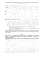
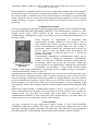
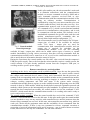
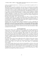
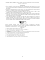
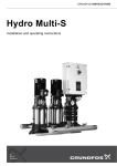
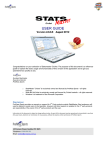
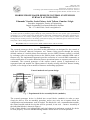
ISSN 1691-5402
ISBN 978-9984-44-071-2
Environment. Technology. Resources
Proceedings of the 8th International Scientific and Practical Conference. Volume I1
© Rēzeknes Augstskola, Rēzekne, RA Izdevniecība, 2011
MOBILE PHONE BASED REMOTE CONTROL SYSTEM FOR
FURNACE AUTOMATION
Edmunds Visockis, Janis Zalans, Artis Teilans, Gundars Valgis
Rezeknes Augstskola, Faculty of Engineering
Latgale Sustainable Development Research Institute
Ph.: +371 64625264; e-mail: [email protected]
Abstract. Nowadays, an increasing role in various technologies holds electronic devices that automate
the various systems to facilitate people's daily life. This publication describes one of those types of automation
capabilities, as a control system using mobile phones and mobile communications. Innovative approaches for
the modification can be used for various purposes, such as a room or vehicle security alarm systems, remote
management for various processes, the heating system furnace firing, the combustion process control, as well as
many other remote management and control purposes.
Keywords: Remote Control Systems, GSM communications, Microcontroller.
Introduction
The research prototype device described in this publication was designed for the control of
solid fuel (firewood, charcoal, briquettes, etc.) furnace firing process through the strictly
defined content of a mobile phone short message service (SMS). Remote control is realized
by exchange with text messages between the mobile phone and the embedded SIM card of
furnace unit. The implemented approach provides execution of received SMS commands, as
well as notification of a sender about the furnace operational status or response to the received
commands. The research prototype of the remote control system is implemented as a
segregated unit and useable for improvement of already existing solid-fuel furnace heating
systems, or for design of new models of furnaces and heating equipment.
Control methods and system design
Fig. 1. Experimental device assembly blocks (modules)
The research prototype device is divided into several blocks (modules) in order to more
clearly be able to view an assembly operation, and to easy carry out a separate block for
configuration and maintenance work if needed. The blocks are: user, communication module,
the control module and the device that will be operated, in our case – furnace. Assembly of
the individual blocks is shown in Figure 1.
Each of these blocks is an indispensable and vital element in equipment, required for device
to work properly. Even one malfunctioning module affects device’s overall operation.
187
Visockis E., Zalans J., Teilans A., Valgis G. MOBILE PHONE BASED REMOTE CONTROL SYSTEM FOR
FURNACE AUTOMATION
Let's take a brief look at all device modules:
User. This part consists of a human and a mobile phone. Correct human action is required
for successful functioning of the device. The human has to make decisions about device’s
performance and control and, by using corresponding commands in the form of an SMS,
send the commands to the device, which device will try to execute and then notify the user
back about command execution status.
Communications module. This part consists of GSM module, SIM card, antenna and
battery. This module is responsible for receiving commands from the user and sending
reports back to the user.
Control module. In this part of pilot study as a key component in this block was used
microcontroller ATMEGA8. Control module is responsible for managing communications
module, instruction receiving and processing as well as status checks and reporting back
to the user. The main task of this block in our experimental case is the furnace firing and
management.
The device, which will be managed. Innovative remote firing and room heating system
uses a specially designed solid-fuel furnace, which ensures 100% fire safety without
human presence. Firing burner is placed in specially designed place inside the furnace.
User fills furnace with the proper fuel to ensure that firing will be accomplished. When
it’s time to remotely kindle the furnace, user sends appropriate command to the control
module from mobile phone. Control module then will read the fuel combustion process
status and if no problems are detected, furnace firing is executed by a specified sequence
algorithm:
1. Open flue damper and turns on smoke pump (if it’s built into the system);
2. After a certain time kindle the fuel;
3. After a certain time read the temperature on the heating element surface and
temperature in the heated room.
If the algorithm by any conditions is not fulfilled in a specific order, fuel ignition process is
stopped. Information about the ignition, fuel combustion and room warming processes is then
sent to the user.
User
In this part user is the most important device operator and coordinator. In this particular
example, the experimental device action directly depends from the user – whether or not
furnace will be kindled.
At beginning to use the remote furnace firing, fuel combustion and room heating information
reading device, each user must prepare device for work. The first thing to do is acquire the
SIM card from the mobile communications operator and activate it. SIM card activation
process differs for various mobile communication operators, but its activation process always
is explained in the user manual, which comes together with the selected mobile
communications operator SIM card.
During the activation process, the SIM card is inserted into a functional mobile phone. When
SIM card is successfully activated, user must create a new contact named ADMIN and save it
into devices SIM card phonebook and allocate it the telephone number from which device
will be controlled. User must do it because by default the device does not respond to
commands, which are sent from any other telephone number, except the one that is assigned
to ADMIN contact. In the pilot studies there was also studied possibility if several users
would be able to control the devices, from which the user ADMIN is the main user with
greatest privileges for device management, and other users named USER with fewer device
use privileges. It is very important to verify that the contact number named ADMIN is saved
directly into devices SIM card phonebook, not the one that is in cell phone's memory.
188
Visockis E., Zalans J., Teilans A., Valgis G. MOBILE PHONE BASED REMOTE CONTROL SYSTEM FOR
FURNACE AUTOMATION
When activation is completed and the necessary contact phone numbers have been assigned,
the SIM card may be inserted into communication module. User is responsible for checking if
the control module is attached to the sensors and the furnace control unit is operational, that
all the equipment units are connected to their appropriate power supplies, as well as to check
whether kindling is properly composited and fuel for the furnaces firing process will be
successful.
Communication Module
As a key component for this experimental communications module in this experimental study
is used branded SIMCOM GSM module SIM300CZ. The GSM module in its basics is a fullfledged mobile phone, which includes all the most essential functions of mobile
communication - making and receiving voice calls, as well as receiving and sending short text
messages (SMS).
These functions are implemented in accordance with
internationally accepted standards, so the module is able to
work without any changes anywhere in the world with any
mobile communications operator SIM card. By creating a
wholesome control module, the communication module can
also be used as a base for mobile phone development, but
because this module is relatively large in size, it will not be
suitable for this task.
Experimentally manufactured communication module can be
viewed in Figure 2. During the experiment, communication
module was fed with a NOKIA cell phone company BL-5C
Fig. 2. Communication
accumulator, which can provide the necessary voltage and
module research
current supply for the GSM module. Although the experimental
prototype
accumulator was providing 3.7 volts and the module worked
correctly, GSM module manufacturer recommends the use of higher-voltage accumulators with the recommended voltage 4.2 volts. [1.]
Communications module can be fully functional only with the active SIM card, that's why
SIM card must be activated (it must be able to register on network, receive calls and receive
short text messages). SIM cards activation procedures are slightly different for various mobile
network communication operators, but activation is one of the few activities that user must do
before starting to use each device. SIM card activation procedure is always explained in the
user's manual, which comes together with the selected mobile communication operator SIM
card.
Without the control module, communication module is able to just register on a network,
receive calls and short text messages, but it can't in any way react to these events, or make any
response action (e.g. send short text message reply to the caller). To successfully use a
communications module it is also required for some external devices - an active SIM card,
antenna, power source (accumulator) and the control module.
Control Module
As a key component for this experimental control module, is used a microcontroller
ATMEGA8 produced by ATMEL. This chip is able to process the signals that enter on the
input pins, and output signals according to the input state. This behavior can be programmed
into microcontroller. Experimentally manufactured control module is shown in Figure 3.
189
Visockis E., Zalans J., Teilans A., Valgis G. MOBILE PHONE BASED REMOTE CONTROL SYSTEM FOR
FURNACE AUTOMATION
In this pilot studies part, the microcontroller's main task
is to maintain connections with the communications
module, to execute command received by SMS and to
reply command responses received back to user.
Communication with the communications module is like
using an ordinary modem. Communication is
established by using only two microcontroller pins (one
of which sends the data, while the other receives). As a
communication protocol used in the pilot studies was
AT-command set [2.], which is an international standard
protocol for communication with modems, and is used
to communicate with the modem. This includes a set of
standardized commands for specific tasks, and also each
modem manufacturer-specific commands that are
directly linked with modem configuration. [3.]
The microcontroller used in pilot studies has 28 input /
output pins, of which 23 are available for end-user
needs. Two input / output pins are used for
communication with communication module, and one
Fig. 3. Control module
output pin is required for switching on the
research prototype
communication module. User can use remaining
available 20 input / output pins, which can be added various types of sensors, or expand
module functionality by using various accessories that after receiving commands from the
communications module can be turned on or off, as well as the communications module is
able to notify the user information about the status of devices.
During the experiment, the control module was fed with 5 volts received from the computer's
USB port power supply. Due to the fact that the microcontroller requires a stable current, the
easiest solution is to take already stabilized current from the computer's USB port, so
avoiding need for specific power supply.
Remote control device work algorithm
Switching on the device and register on the available network. Once the user has pressed the
devices power on switch, current is passed to the control module. The control module controls
the voltages and connected devices status (if any) and if determined that the processes are
running in the corresponding mode, the control module switches on the communication module.
Communications module after receiving switching on impulse, in addition controls the used
voltages, working temperature and SIM card status. If the system works correctly,
communication module starts to register on to the available network. Registering on to the GSM
network is done by GSM module, which has already built-in network registration protocol and
methods, which operate on the internationally accepted standards. If registration process to the
network has been completed successfully, the control module receives the command "CALL
READY", which means that the communications module is in working order and is ready to
receive and send text messages.
The control module operation. When the control module has received the command "CALL
READY", a microcontroller moves to the idle state. In this pilot studies part, the control module
was not intended to carry out any activities with controlled device until the moment when the
furnace firing command was received. In idle state, microcontroller runs endless loop, which in
each cycle, checks all the equipment status and the availability of new commands from the
communications module. If there is any new command to execute, command execution or
processing of received information begins and if necessary - user is notified about executions
results, but if there are not any new commands - the idle state continues.
190
Visockis E., Zalans J., Teilans A., Valgis G. MOBILE PHONE BASED REMOTE CONTROL SYSTEM FOR
FURNACE AUTOMATION
The responses to the events and commands. In the experimental example, voice calls were not
used, so the control module automatically rejected incoming calls, as soon as they are received.
Communications module from time to time notifies the control module about the status
changes, such as low battery level, incoming call or SMS. Part of these events is insignificant
and they don't affect overall functioning of the device modules, but some events are very
important. For example, if the control module receives the status "UNDER-VOLTAGE
WARNNING" from communication module, it means that the communications modules
accumulator voltage is too low and the communications module will soon be automatically
turned off if not connected to external power supply - accumulator charger. Communication
module will still able to operate for a while, but before the automatic shutdown control module
receives the last status report from the communications module - "UNDER-VOLTAGE
POWER DOWN". Following this announcement, communication module is no longer able to
perform as a result the device is not able to receive commands and transfer status reports
anymore.
The responses to the errors. Unfortunately, the device is unable to anticipate and prevent errors,
so all errors must be prevented while programming the control module. By default, in case of
the error, the control module to notify the user about the error and device management will be
stopped. However, through prudent control module programming, it is possible to develop
solutions that allow to predict these errors and, where possible, prevent them and continue
normal operation of the device.
Unit Testing
In this work there has been carried out communication and control modules design and
experimental prototypes development, based on the available manufacturer’s recommendations
and Internet resources.
The first thing was to develop the control module. As the base for it, was used solution found on
robot forum [4.] that allows full use of all possible microcontroller ATMEGA8 features. When
the experimental control module prototype board was designed and the parts were soldered,
control module testing and programming part was launched.
As first task was set to provide the communication module communication with the computer.
To achieve this, the computer must be prepared at first. Also we needed to program a library
that will provide data input and output to / from the microcontroller.
As part of this experiment was a hypothesis that the developed scheme will be operating
successfully with maximum data exchange rate, based on a microcontroller technical
documentation. [5.]
To realize Experimental data exchange it was used on a computer that is running Ubuntu 9.10.
Different standard RS232 port speeds were used [5., 6], using different amount of data. As a
successful outcome of the experiment, in the terminal Putty was observed correctly received
text (data) with no errors, proving that, each sent text bit is successfully received. As fastest
possible data transfer speed was used 115200 bits per second, which is both a communication
module and control module maximum data exchange rate.
Communications module design was based on the GSM module manufacturer - SIMCOM
offered education board. After examining available technical documentation from manufacturer
for hardware design [1.], keeping recommendations in mind we developed suitable scheme for
the experiment. Based on scheme we made the board drawing and communications module.
(See Figure 2.)
The factory default settings for GSM module was that it will operate with not fixed data transfer
speed (autobouding), which means that the GSM module will automatically "agree" with the
computer for maximum data transfer speed, both of which are acceptable to computer and GSM
module. The control module is unable to work in this mode, so the AT commands [3.] were
191
Visockis E., Zalans J., Teilans A., Valgis G. MOBILE PHONE BASED REMOTE CONTROL SYSTEM FOR
FURNACE AUTOMATION
used to set a fixed data transfer rate to 115200 bits per second, which is acceptable as a PC, so
the control module.
When all modules were able to communicate with each other, was launched the control module
functionality programming. Programming took place through an integrated development
environment Eclipse. [7.] This environment was chosen because it is easily adaptable to the
needs; it has a lot of free publicly available plug-ins that allow expanding functionality of the
environment. To write a program code into microcontroller, AVR Eclipse Plug-in was used. [8.]
It is a simple and easily customizable plug-in, it supports various programmers, including
USBASP programmer used in this experiment. [9.] All documentation and software needed to
build the programmer is available free of charge in developer's website, which makes this
programmer a cheap and easily produced device even at home. Also, the data recording speed to
the microcontroller surpasses many other programmers.
Recording microcontroller code is done by pressing the button in Eclipse development
environment, which appears by installing AVR Eclipse plug-in. Microcontroller's logic was
programmed using C programming language. Due to microcontroller architecture differences, a
lot of problems were faced, as conventional solutions that work on computer, do not work on
microcontroller, so we had to look for other solutions.
Beginning control and communications module development one needs to understand the
manufacturers given information. Also, knowledge in electronics, programming and computer
architecture were used. As a result of the experiment, are communications and control modules
that are able to work and is already practically tested in real applications. The control module
logic still has some gaps and deficiencies, but they are being corrected. Work is mostly based on
error prediction and prevention in order to make the device more stable and automatic without
requiring the user to interaction.
Potential applications
Device can be relatively easily adapted to different purposes, where the SMS communication
with the device is necessary, respectively, by reprogramming the control module logic for
each specific task. In this scientific study, a prototype device will be used for solid fuel
furnace firing after receiving the appropriate SMS command. The control module is
connected to the device that will accomplish the ignition process. It consists of relays and
some optional equipment that provides furnace firing process. Successful furnaces firing also
depends on whether it will be properly prepared for fuel ignition, material (in this case, the
correctly composited kindling) or fuel (firewood) will be properly composited into furnace,
dry enough, etc.
If the device will be used for sensors reading and periodic reporting of results (such as furnace
temperature and temperature in heated room), it is necessary to develop a specific
mechanisms to manage the sensors and receive the data from them. The other measurement
specific changes need to be made only to the control module by reprogramming
microcontroller.
As the control module main part can be used any microcontroller, not the one used in the
experiment. Depending on the application and the controlled device complexity, it is possible
to use other microcontrollers, which differ mainly with the microcontroller's processor speed
and data transfer rate, as well as available to the user input/output pins. For example,
ATMEGA64 microcontroller enables the user to use more than 40 input/output pins, which
should be in fact enough for any remote-control device.
192
Visockis E., Zalans J., Teilans A., Valgis G. MOBILE PHONE BASED REMOTE CONTROL SYSTEM FOR
FURNACE AUTOMATION
Conclusions
1. In this scientific research developed innovative communication and control unit was used
for solid fuel furnace firing, the combustion process and the heated room heating dynamics
monitoring.
2. Innovative communication and control device can be successfully used for various process
controls, for example, alarms, security and many other purposes.
3. The maximum experimentally determined speed at which the device is able to work
without any data loss during transmission is 115200 bits per second.
4. In the future there is a need to realize control algorithm improvement. At the moment there
is no chance to work with control SMS queue (for example in multi-users mode when users
send commands to the device separately).
5. At the moment algorithm is working linear and each control command will be treated as
separate command. But in multi-user mode, there is a need to be able to share resources
between all users and to prevent commands collisions (for example USER sends command
to fire the furnace, but the ADMIN has already fired the furnace).
Acknowledgments
Eiropas Reģionālā attīstības fonda līdzfinansētais projekts „Energosistēmu efektivitātes
paaugstināšanas, izmešu attīrīšanas un klimata izmaiņu samazināšanas hibrīdtehnoloģijas”, projekta
vienošanās Nr. 2010/0267/2DP/2.1.1.1.0./10/APIA/VIAA/169
1.
2.
3.
4.
5.
6.
7.
8.
9.
References
SIM300C Hardware Design, SIMCOM, 12.05.2008
Hayes command set, http://en.wikipedia.org/wiki/Hayes_command_set
SIM300C AT Commands Set, SIMCOM, 31.07.2007
Универсальный робо-контроллер MRC28, www.robozone.su/2008/02/29/universalnyjj-robo-kontrollermrc28.html
ATMEGA8 documentation, www.atmel.com/atmel/acrobat/doc2486.pdf
RS-232 specifications, http://en.wikipedia.org/wiki/RS-232
Eclipse Integrated Desktop Enviroinment, www.eclipse.org
The AVR Eclipse Plugin, www.avr-eclipse.sourceforge.net
USB programmer for Atmel AVR controllers, www.fischl.de/usbasp/
193