1
Digital Force Feedback Slider:
Software Design and Implementation
Master of Science Thesis
ALI SHAHROKNI
Department of Computer Science and Engineering
Division of Human Computer Interaction
CHALMERS UNIVERSITY OF TECHNOLOGY
Gothenburg, Sweden, 2007
Digital Force-Feedback Slider: Software Design and Implementation
Ali Shahrokni
© T2I lab
Examinator and supervisor:
Associate Professor Morten Fjeld
Department of Computer Science and Engineering
Chalmers University of Technology
Gothenburg, Sweden
Telephone: +46 - 31 - 772 1000
2
Abstract
This report presents and discusses software realization for a user interface device called
force-feedback slider. Our force-feedback slider is a one-dimensional actuated device
connected to a host computer via USB. The main feature of this device is its ability to
display force to its user and estimate the force employed by the user’s hand. The work
started as a project to improve the functionality of an existing analogue device. Since the
analogue device was difficult to control, a new digital device was designed and realized.
In this report the modelling and implementation of the new device is discussed and the
results and potential future works are represented.
3
Acknowledgement
My master thesis work was conducted at T2i lab at Chalmers University of Technology
in Gothenburg Sweden. The project included 20 academic credits and is conducted as an
end phase to my master program in computer engineering.
This project was defined and supervised by Morten Fjeld. Here I want to thank him for
all his help, effort and support which made the conduction of this interesting project
possible for me. I thank Julio Jenaro for his work on the hardware of the system and his
helpfulness. I also want to thank the other members of the T2i lab for their constant
support and help and for providing a nice, calm and friendly atmosphere to work in.
4
Contents
Abstract............................................................................................................................... 3
Acknowledgement .............................................................................................................. 4
Contents .............................................................................................................................. 5
Definitions .......................................................................................................................... 6
Acronyms............................................................................................................................ 7
1
Introduction................................................................................................................. 8
1.1
Purpose of the Project ......................................................................................... 8
1.2
Potential Applications......................................................................................... 8
1.3
Problem Definition.............................................................................................. 9
1.4
Previous work ................................................................................................... 10
1.4.1
Analogue Slider ........................................................................................ 10
1.5
Report Structure ................................................................................................ 10
2
Employed Technologies ........................................................................................... 11
2.1
Analogue-Digital Converter (ADC) ................................................................. 11
2.2
ASIO (Audio Stream Input/Output).................................................................. 11
2.3
Atmel ATmega8................................................................................................ 11
2.4
I2C..................................................................................................................... 11
2.5
Pulse-Width Modulation (PWM)...................................................................... 12
2.6
USART (Universal Asynchronous Receiver/Transmitter) ............................... 13
3
Analysis .................................................................................................................... 14
3.1
Hardware Design .............................................................................................. 14
3.2
Requirements .................................................................................................... 17
4
Software Design........................................................................................................ 19
4.1
Slider Functionality........................................................................................... 19
4.1.1
PWM ......................................................................................................... 19
4.1.2
Functioning Modes ................................................................................... 19
4.1.3
AD/DA Converters ................................................................................... 20
4.1.4
Interpreting the User Force ....................................................................... 21
4.2
Communication between Board and Sliders (I2C) ........................................... 22
4.3
Main Board Functionality ................................................................................. 22
4.4
Communication between Board and Computer (USART) ............................... 22
4.5
API .................................................................................................................... 23
5
Software Implementation.......................................................................................... 25
5.1
Implementation Languages and Environment .................................................. 25
5.2
Integration and Test .......................................................................................... 27
5.3
Problems ........................................................................................................... 27
5.4
Final product ..................................................................................................... 28
6
Conclusion ................................................................................................................ 30
6.1
Future work....................................................................................................... 31
7
References................................................................................................................. 32
Appendices........................................................................................................................ 34
A - User Manual............................................................................................................ 34
B - Communication protocols....................................................................................... 35
C – Conference Paper 1, 2006: ..................................................................................... 36
D – Conference Paper 2, 2007: ..................................................................................... 41
5
Definitions
Lookup table is a data structure and in our case an array with different values for
different parameters that can be looked up from the memory by the program. This
reduces the delay and computations done by the processor.
Application or application software is a part of the computer software which uses the
basic functionality given by the different devices and drivers and services to
provide functionality to the user or perform a specific task on the computer.
Java is an object-oriented programming Language. Java was developed by Sun
Microsystems during 1990s.
Embedded system is a computer designed for a specific purpose and only performs the
tasks that are predefined for it.
Host computer When an external device is connected to a computer, the computer is
called host to that device.
6
Acronyms
OS
I2C
TWI
USB
ASIO
ADC
DAC
PWM
LUT
FF
FFS
API
RISC
USART
UART
Operating System
Inter-Integrated Circuit
Two-Wire Interface
Universal Serial Bus
Audio Stream Input Output
Analogue-Digital converter
Digital-Analogue converter
Pulse width modulation
LookUp table
Force Feedback
Force Feedback Slider
Application Programming Interface
Reduced Instruction Set Computer
Universal Asynchronous Receiver/Transmitter
Universal Asynchronous Receiver/Transmitter
7
1 Introduction
This report discusses the process and results of digitalizing the platform of a force
feedback slider. This project has been done as a master thesis at the Computer Science
and Engineering department at Chalmers University of technology in Gothenburg,
Sweden. The project started in summer 2006 and ended in February 2007.
In the physical world much information is received with the help of the tactile sense.
Most often this information is unique for this sense and can not be received from any
other perceptual channel. Human beings have a fast sense of touch [1] and we are used to
receive tactile feedback to build a better comprehension of things. In the computer world
most of the information is received via the visual and hearing senses. In some cases this
might overload the visual channel. Furthermore much information normally received in
the everyday situations is not attended. To overcome this gap between the digital and
physical world some efforts from research and industry has been made. Most of the
existing force feedback systems that were available before the start of the project like
Phidgets [2], iStuff [3] and commercial force-feedback joysticks have had force as output
and not input, therefore not being able to interpret the user force fully. Most of the
systems even lack the capability to dynamically steer and control the output force in a
quick and natural way and the feedback is widely by vibrations of different frequency and
intensity.
1.1 Purpose of the Project
Research about user interface devices with force feedback is relatively new. Hoping to
make progress in the field, the force-feedback slider (FFS) project was started. The
project was designed to build a system to operate with force in addition to position as
input and output. To prove this concept the analogue slider was built in the scope of
another master thesis performed at Chalmers University of Technology. The system
presented large delay and instability trying to create some force feedback. The system
also had some integration issues with different computers and platforms.
These facts required us to make a new digital platform, a more stable system with less
delay to give the user a better feeling of a continuous force feedback.
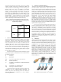
1.2 Potential Applications
The physical sliders are used to easily control one-dimensional parameters of systems.
Today the sliders are more advanced and can dynamically be controlled by digital
systems. Adding a force feedback feature to a slider can be interesting for many
applications. Some of those applications are:
•
For education purpose: The FFS can be used to simulate physics laws and even for
learning of multi-dimensional mathematical models in other fields.
8
•
In industrial machines: An example can be steering a robot or machine from
distance. This is of course possible now but the extra force feedback feature makes
the control much more accurate and natural. This has of course been already used in
some industries, but the cost of the devices there are much higher than the one we
provide.
•
Medicine: This device can be used for remote controlling a surgery robot or it can
even be used for optimization purposes in medical treatments.
1.3 Problem Definition
According to the purpose of the project a system with the following properties is
required:
•
•
•
•
•
•
•
•
•
•
•
•
The system should consist of up to 16 one-dimensional actuated sliders.
The device should be able to connect to the computer via USB.
The system should be OS-independent.
It should be able to operate with different forces and dynamically change the forces
during operation.
The force and position should be available as input and output for each and every
slider in the system.
The sliders should respond to the orders sent by the computer in less than half a
second.
The user should feel the feedback as a smooth and continuous force. The human
tactile sense detects forces with frequency less than one KHz as inconsistent.
Therefore to generate a smooth and continuous feeling the sliders should operate with
a frequency more than this amount.
The system should be stable and perform its functionality as long as the user wants it
to. It should even be independent of any computer settings that are not directly related
to the device.
The system should provide a standard and easy to use API for developing
applications easily.
The sliders should be able to cooperate and work synchronously if the application
requires that.
The following force functions should be accessible to application programmers:
o User mode: Allowing the application to control the slider directly during runtime
o Function mode: Creates forces according to polynomial functions.
o Lookup table mode: slider behaves according to the specifications in the
lookup table sent to it.
Each slider should have a button implemented which can have different
functionalities depending on the application. This functionality can be chosen by the
application via the API.
9
•
Each slider should have a diode onboard that can be turned off an on by the
application via the API.
1.4 Previous work
This part introduces the background of the project as it was before the start of this master
thesis.
1.4.1
Analogue Slider
The analogue FFS [4][5]is a motorized potentiometer, previously part of a sound mixer.
The digitalization of the signals from the slider is done by an external sound card
connected to the PC via USB. A special circuit is designed and put on top of the sound
card that takes care of the conversions and other necessary tasks. When the converted
digital values come to the PC from the sound card they are processed. When they are
ready they will be sent as digital signals to the sound card and there they are converted to
analogue voltage understandable for the slider motor.
Analogue FFS features five predefined modes. In position, the slider is used only as input
device, the motor is switched off, and the user can move the slider without FF. In
elasticity, default position and maximal force are set and the user’s fingers have to
overcome this force. When the handle is released, it returns to the default position.
Gradual offers a number of discrete steps into which the handle can snap. In texture,
high-frequency low-intensity vibrations are applied to the handle, thus giving users an
impression of a rough surface. In oscillation, the handle comes to rest after a damped sine
movement. These five haptic profiles are abstract descriptions of FF capacities; other
applications can be composed from these modes.
1.5 Report Structure
The report is offered in eight parts. The Introduction gives an overview of the
background and goals of the project. The Employed Technologies are summarized and
presented in the next part. In the Analysis section, the approaches are discussed. The
final Software Design is given after the analysis section. Software Implementation and
Testing show how the design was followed and realized to achieve the project goals.
Finally, the Conclusion and future works will end this report.
10
2 Employed Technologies
The technologies used during the project are briefly presented in this chapter. This is just
a short reference and description and more information can be found following the
references.
2.1 Analogue-Digital Converter (ADC)
An AD-converter is a circuit that converts continuous signals to discrete digital values. A
DA-converter performs the opposite task. In the case of this project the AD/DA
converters convert the continuous voltage to digital values understandable by the
computer or the other way around.
The resolution of the conversion is the different number of digital values that the
analogue signals can be converted to. The resolution is usually expressed in bits.
Meaning if the ADC produces 1024 different values it is said to operate with 10-bit
resolution (210 = 1024).
2.2 ASIO (Audio Stream Input/Output)
ASIO [6][7] is a protocol for low latency digital audio designed by Steinberg. ASIO is an
application program interface toward the sound card. Unlike Microsoft’s DirectSound
which usually is for stereo input and output, ASIO can handle several input and outputs.
This technique is used by recording studios and professional musicians due to its low
delay and the possibility of several input and output channels. The low delay provided by
this method is due to the bypassing of the operating system audio mixing kernels. Hence,
ASIO can communicate directly with the audio hardware.
2.3 Atmel ATmega8
According to Atmel Atmega8’s datasheet [8]:
“The ATmega8 is a low-power CMOS 8-bit microcontroller based on the AVR
RISC architecture. By executing powerful instructions in a single clock cycle, the
ATmega8 achieves throughputs approaching 1 MIPS per MHz, allowing the system
designer to optimize power consumption versus processing speed.”
2.4 I2C
According to wikipedia.org [9]:
“I²C is a multi-master serial computer bus invented by Philips that is used to attach
low-speed peripherals to a motherboard, embedded system, or cell phone. The name
stands for Inter-Integrated Circuit and is pronounced I-squared-C and also,
incorrectly, I-two-C. As of October 1, 2006, no licensing fees are required to
11
implement the I²C protocol. However, fees are still required in order to obtain I²C
slave addresses.
I²C uses only two bidirectional open-drain lines, serial data (SDA) and serial clock
(SCL), pulled up with resistors. Typical voltages used are +5 V or +3.3 V although
systems with other, higher or lower, voltages are permitted.
The I²C reference design has a 7-bit address space with 16 reserved addresses, so a
maximum of 112 nodes can communicate on the same bus. The most common I²C
bus modes are the 100 Kbit/s standard mode and the 10 Kbit/s low-speed mode, but
clock frequencies down to zero are also allowed. Recent revisions of I²C can host
more nodes and run faster (400 Kbit/s Fast mode and 3.4 Mbit/s High Speed mode),
and also support other extended features, such as 10-bit addressing.
The maximum number of nodes is obviously limited by the address space, but also
by total bus capacitance to 400 pF.”
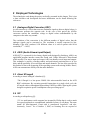
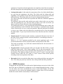
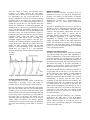
2.5 Pulse-Width Modulation (PWM)
According to wikipedia.org [10]:
“Pulse-width modulation (PWM) of a signal or power source involves the
modulation of its duty cycle, to either convey information over a communications
channel or control the amount of power sent to a load.
Pulse-width modulation uses a square wave whose duty cycle is modulated
resulting in the variation of the average value of the waveform. If we consider a
square waveform f(t) with a low value ymin, a high value ymax and a duty cycle D
(see figure 1), the average value of the waveform is given by:
As f(t) is a square wave, its value is ymax for
. The above expression then becomes:
and ymin for
This latter expression can be fairly simplified in many cases where ymin = 0 as
. From this, it is obvious that the average value of the signal (
is directly dependent on the duty cycle D.”
12
)
2.6 USART (Universal Asynchronous Receiver/Transmitter)
According to wikipedia.org [11]:
“A universal asynchronous receiver/transmitter (usually abbreviated to USART or
UART) is a type of "asynchronous receiver/transmitter", a piece of computer
hardware that translates data between parallel and serial interfaces. Used for serial
data telecommunication, a UART converts bytes of data to and from
asynchronous start-stop bit streams represented as binary electrical impulses.
A UART is usually an individual (or part of an) integrated circuit used for serial
communications over a computer or peripheral device serial port. UARTs are now
commonly included in microcontrollers (for example, ATMEGA8). Many modern
ICs now come with a UART that can also communicate synchronously; these
devices incorporate the word synchronous into the acronym to become USARTs.”
13
3 Analysis
With the analogue system as a proof of concept, the project had come to its next step. In
this step we wanted to build a stable prototype with more functionality than the existing
device. In order to fulfil the requirements listed in 1.3 several solutions were suggested.
In the beginning we were looking for another analogue solution which could improve the
existing system without the need to change the whole system. In order to do this we
searched for better technologies than DirectSound to work with the signals in the sound
card. Some different possible technologies were explored and the best one suited for this
project was the ASIO technology. ASIO is a low delay, fast technology with ability to
operate with several simultaneous inputs and outputs. The problem we encountered was
that the sound card we were using was not fully compatible with ASIO. It was also hard
to manage several sliders connected to the same card even with this technology. After
some studies on this technology, we decided not to use the analogue platform any more
and start building a new slider from scratch.
After exploring the different options and brainstorming with different experts in the area
we decided to create a fully digital solution. In this solution microcontrollers with
integrated AD/DA converters would be installed on the sliders in order to control their
performance characteristics. The desired performance characteristics would be coded as
lookup tables by the application running on the computer and sent to the memory of the
microcontrollers. The microcontrollers would be able to decode the tables and move
accordingly.
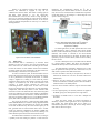
3.1 Hardware Design
The hardware of the sliders was designed by Julio Jenaro and the following is a quote
from his report on the design of the hardware [12]:
“The hardware design is manifold. Initially the system has to be able to control up
to sixteen sliders. This can be achieved having one microcontroller in charge of the
control of the sixteen motors and also of the communication with the PC using the
USB protocol. In this case the motors could also be connected in a modular manner.
14
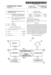
Figure 1: Diagram for only one microcontroller
After several simulations and studies, this first approach was discarded because
despite it could accomplish the requirements of the controllability, it would require
a very complex programming to optimize the timings in the motor control.
Furthermore, this configuration would not be useful for future applications where
more sliders were required, because only one microcontroller to control all the
motors will take a lot of resources. A general description of this schematic is
presented in Figure 1.
This option was discharged in favour of the final option of using one
microcontroller to manage the communication with the PC and the different slider
boards. This option may be not cheaper but introduce high range of modularity in
the system, not only making it easier to redesign the system but also to fix the slider
in case they break. In addition, this option was chosen in order to reduce the latency
in the control of the motor, which was one of the priorities in the project.
The microcontroller Atmega8 was proposed for the project in due to its reduced
price and its RISC architecture, contributing to a relatively easy programming of the
firmware. This determined the hardware design in the main board and also in the
slider board. The same microcontroller was chosen for both boards in order to
facilitate the firmware programming, because in both cases no more flash memory
was required and the number of resources was enough to fulfil the requirements in
both kinds of boards.
15
Figure 2: Diagram for the final hardware design
In order to communicate the slider boards and the main board it is necessary to
design a communication bus. The I2C bus was chosen because it is easy to program
and it allows connecting high number of devices and high communication speed.
Meanwhile it also has a simple design Thanks to this protocol it could be possible in
a future work to add EEPROM memories in a modular manner if more memory is
required and also LCD screens.
Another requirement was to communicate the system with a PC. This can be
achieved in different ways: serial port, parallel port, Bluetooth, infrared … At the
end the USB connection was chosen because it tolerates high communication speed,
it can be easily recognized by the operative system in the PC. Other important
reason was its reduced cost and easiness to use and program the communication
parameters. “
To generate different forces some options were available. The principle is to put different
voltages over the slider motor to get different forces. Since the power supply generates a
constant voltage, a technique should be used to regulate the voltage to different values.
The technique that was chosen was PWM. In PWM the voltage is supplied to the motor
for a quote of the time and for the rest of the time the voltage is zero. Using this
technique the force experienced by the user is the mean of all the forces generated by the
motor. This force will be experienced as continuous if the voltage over the motor is
changed with high frequency. The final hardware design is shown in Figure 2.
Some other requirements of the device were that each slider should have a dedicated
button and diode. These parts should be controllable by the application running the slider.
16
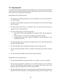
3.2 Requirements
According to the hardware design presented in the previous section, the system is divided
in three parts: the slider board, the main board and the host computer. Each of these parts
has its own software design and requirements.
Requirements for the slider board are:
•
The frequency of PWM generated by the microcontroller on the board should be
more than 10 KHz.
•
The slider board should be connected to the main board via its TWI module running
the I2C protocol.
•
The slider board should take the commands from the main board and return the
requested values to the main board.
•
The slider should operate in the following modes
o User mode: Allowing the application to control the slider directly during runtime
o Function mode: Creates forces according to polynomial functions.
o Lookup table mode: slider behaves according to the specifications in the
lookup table sent to it.
•
The slider should be able to read the force applied by the user to the slider handle and
position of the slider handle.
•
The slider should be able to dynamically change its force during run-time.
•
The microcontroller should be able to recognize if the button on the board is pressed
or not.
•
The microcontroller should be able to turn the diode on and off.
Requirements for the main board are:
•
The main board should be connected to all the active sliders via an I2C connection.
•
The main board should be connected via its USART interface to the USB chip
onboard. This USB chip should connect to the computer and speak to the active
program using the defined protocol for this communication.
•
The main board should operate as a gateway between the sliders and the computer. It
should forward the commands of the application running on the computer to any
17
specified slider and it should answer the requests made by the application. These
requests are the parameters of the sliders or the main board.
Requirements for the driver and API installed on the host computer are:
•
•
The API should work for all operating systems.
The slider functionality should be independent of any settings on the computer.
•
The driver should be able to connect to the main board(s) connected to the computer.
It should send and receive necessary information following a specific protocol also
known by the main board.
•
The API should provide standard and easy-to-use functions for the programmers
developing software using the sliders.
18
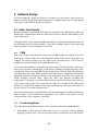
4 Software Design
Given the hardware design the software is divided in several layers. Some layers are
directly related to the physical boards and some are communication layers. In this chapter
all the parts of the software design are discussed.
4.1 Slider Functionality
The microcontroller onboard the slider board is responsible for controlling the slider and
handling the communication with the main board. In this section the functionality of the
slider is discussed.
The functionality of the slider is mainly controlled by setting and reading the values of
the different ports of the microcontroller. To be able to manage when to set the ports and
what to set them to some technologies were used.
4.1.1
PWM
Due to the design of the hardware of the force feedback slider, the voltage sent to the
slider motor is always either zero or the maximum voltage of the system. Using these two
voltages we can only produce one force which is the maximum force. This is done by
sending the maximum voltage to the slider motor all time.
To overcome this problem we should let the motor work with full speed for a part of the
time and rest for the remaining part. If the motor is running with high frequency, these
interruptions will not be noticeable by the human sense of touch. Since the maximum
operating frequency of the PWM applied to the slider motor is around 20 KHz and the
minimum frequency detected by human to be inconsistent is 1 KHz if we chose any
PWM frequency between these values the slider will function according the
requirements. Doing this we produce different forces, because the force felt by the user
will be the average of the force created by the slider. For example if the slider works
during 30% of the PWM length and rests the remaining time, the force experienced by
the user will be 30% of the maximum force.
Since the produced torque is proportional to the current through the winding in the motor
and the torque is the resultant force multiplied by the “radius of the motor”, we can
always perform a force control over the slider.
4.1.2
Functioning Modes
The slider functions in different modes. These modes are listed and explained bellow:
•
User mode: In this mode the slider tries to get to a specific reference position
applying a specific force. The force and the reference position are received from the
19
application. Using this mode the application can completely control the movements of
the slider during run-time and depending on any new event a new action can be taken.
•
Lookup table mode: In this mode the instructions of how the slider should behave
are sent from the beginning to the slider. The slider reads the lookup table and
depending on the position of the slider and the direction of movement it performs
different actions. The lookup table can of course be changed during run-time.
The values in the table are intervals of position and what force should be applied in
those intervals.
The difference between this mode and the user mode is that in this case you know
from the beginning how you want the slider to behave, but in the user mode you
figure out the next action taken just when something happens.
The lookup table mode is a very general mode and specializations can be made. One
useful specialization is the Tick-mode. The Tick-mode is a standard for the software
sliders. In this mode we receive some tick positions. When the position of the handle
is close to one of those ticks, the slider moves toward the tick as if the tick absorbs
the slider handle. To get away from the tick more force than the usual force should be
applied.
•
Function mode: The function mode simulates a polynomial function as the force of
the slider. In the currently realized version the function is a second degree function.
F = a1 * x2 + a2 * x + a3
Where a1, a2, a3 are constants provided by the current application and x is the
deviation between the reference position and the current position of the slider.
This mode can simulate very useful and common functions like the movement of a
spring, which is F = k*x.
•
Program mode: Using the program mode you can make the slider follow a certain
path with certain forces. This is done sending a LUT to the microcontroller. This
lookup table specifies the next goal position and with what force you want to get to
that position. The difference between this mode and LUT mode is that this mode
operates actively while the LUT mode is a more resistive mode which operates
according to the current position of the slider.
•
Rest mode: In the rest mode the slider motor is not working and it dose not apply any
force. The slider just passively reads the value of the position and other parameters.
4.1.3
AD/DA Converters
Atmgega8 has four pins that can be dedicated to digital-analogue conversion. In the slider
these four pins are dedicated to reading the current running through the motor, voltage
over the motor, the button and finally the position of the slider handle. All the AD
conversions are set to convert the analogue signals to digital values of 8-bit resolution,
besides the current which is measured by 10-bit resolution.
20
The voltage pin is used to detect the voltage over the motor. This can be used for
calibrating the different systems. By using different PWM pulses depending on the
voltage two different sliders can produce the exact same force.
The value of the current is used to detect the user force. The current is measured with 10bit resolution for getting a more accurate result of the user force. More about this is
discussed in the next section.
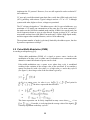
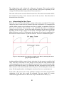
4.1.4
Interpreting the User Force
When the user moves the slider handle a torque in the motor is produced. This torque
changes the motor current from the standard value that it should have. By comparing this
current with the current received when no user force is applied, as estimation of the user
force can be calculated. This deviation is very small and this makes it very hard to
calculate a precise user force. On the other hand the amount of the deviation is different
depending on the average voltage over the motor. The higher slider force applied, the
higher deviation is received. Unfortunately this deviation is not linearly proportioned to
the slider force and is therefore very hard to calculate. This fact is illustrated in Figure 3.
Figure 3: Interpreting the force that the user applies to the slider by measuring the current
going through the slider motor.
Another problem with the current is that it takes time for the current to reach the final
value. This time is called the rise time. Because of this, unlike the other parameters that
can be measured any time, the current should be measured in the very last moment of the
period of PWM that the motor is on. Although anti-noise precautions are used, all the
other activities in the microcontroller make the process of calculating the current very
noisy. All this together makes calculating the actual user force to a very hard process.
In the end of the project some of the problems could be solved and an approximate
calculation of the user force could be performed. This was tested in a remote
collaboration application that was done in the scope of another master thesis [13].
21
4.2 Communication between Board and Sliders (I2C)
The communication between the main board and the sliders is done via the TWI module
of the microcontrollers. The communication protocol used is I2C. In the hardware the
I2C bus starts from the main board and connects all the sliders together in a series
connection.
In the software layer the main board is operating as the I2C master. Each slider has a
unique slave address. When a packet is sent to the slider’s slave address, a connection is
started.
In the initialization process, the master (main board) addresses all the possible slave
addresses. If any slider responds, the main board saves its address for future
communication. After handshaking with all the connected sliders, the main board now
wants to gather information from the sliders. Since the board is the master and only the
master can initiate an I2C communication, the board starts to address each and every
slider in order. The board can operate in the following two different ways. The first one is
default.
• The board asks for all the parameters of the sliders. In return the slider answers with
all the information and when done, the connection is terminated and the board
addresses the next slider.
• The second solution is that the board asks the slider if anything has changes. The
slider sends a byte representing what parameters have changed, following that the
new values of the parameters.
4.3 Main Board Functionality
The main board does not have any operational duties. It just acts as a gateway for
connecting the sliders to the computer. The reason why the sliders are not connected
directly to the computer is to avoid having several USB modules and cables. This would
also increase the amount of data processed by the computer which would be an undesired
result. The main board functions as I2C master. It receives the data from the sliders and
sends the interesting values on to the computer via the USB module.
4.4 Communication between Board and Computer (USART)
The microcontroller on the main board sends the data that should be sent to the computer
to the USB chip via its USART module. It also receives the data sent by the application
in the reversed way. The data sent by the main board can have the two following forms.
This depends on the configuration decided by the application.
• In the first mode, the main board receives the data from the sliders. It keeps track of
all the changes in the slider parameters. When something changes it sends the event
on to the computer.
• In the second mode the main board does not send anything to the computer unless it
has been asked to do so.
22
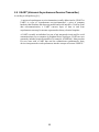
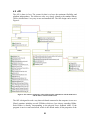
4.5 API
The API is done in Java. The reason for that is to have the maximum flexibility and
platform independency. The sliders are also very closely related to the standard library
JSlider which allows a very easy-to-use and standard API. The API design can be seen in
Figure 4.
Figure 4: The software architecture of the API designed to communicate with the main board
and the sliders connected to the board.
The API is designed in such a way that each board connected to the computer is seen as a
JPanel container including several FFSliders which are Java classes extending JSlider.
Each JSlider is directly corresponding to the physical force feedback slider. If the
program is run in event based mode, which is the default mode, all the properties of the
23
FFSlider objects are automatically updated to correspond to the properties of the physical
slider. This feature allows the user of the API to have access to all the values of the slider
and have a graphical JSlider corresponding to each slider without having to write more
than two rows of code.
Sending commands to the sliders is just as easy as reading their values. By calling a
simple function the application is able to set any parameter of the slider. The user can
even add a PropertyChangeListener to watch the changes in the sliders and act according
to them.
24
5 Software Implementation
The implementation phase started by testing some very simple programs to test the
functionality of the hardware and make sure all the parts were functioning as they were
supposed to, for example the movement of motor and reading of the position. Since the
design and realization of the hardware was going on in the same time as the software
much of the hardware bugs were found and fixed before the implementation started.
After making sure of the functionality of the essential parts of the slider the
implementation was divided into several phases. These phases are listed below:
•
Movement of one slider with different operation modes. The lookup tables and the
coefficients of the polynomial equations are hard coded into the code in this phase.
Make sure the right value is read from the AD/DA converters.
•
Fixing the I2C protocol for one slider. Make sure the right data is sent over the
channel.
•
Completing the I2C protocol for several sliders and make sure commands sent from
the main board are executed at each slider.
•
Sending data from main board and receiving them in the computer.
•
Creating the API and receiving data and sending commands from the computer to the
sliders.
•
Fixing events in the main board and the slider board
After each phase a test and integration phase is performed to make sure that all the new
functionality is working and the previous functioning parts are still running properly.
5.1 Implementation Languages and Environment
Implementation of the code for the microcontrollers was done in the programming
language C. The programming environment was AVR studio 4.0 [14] which is a special
made editor and C compiler for AVR embedded systems. This program could compile
the C files and converted them to HEX-files which could be programmed directly to the
microcontrollers.
Since the choice of Java for the API, Eclipse [Error! Reference source not found.]
which is a powerful Java development environment was used. The classes used were
mostly the standard classes of Java 1.5. An extra library called FTD2xx was added for
handling some parts of the USB communication. [16]
25
All the coding was done under the operative system Windows XP with service pack 2.
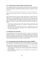
D2XX driver and dll-file [17] were installed on the PC. This made the computer able to
recognize the main boards connected. The drivers were for the communication between
the PC and the USB chip installed on the main board. After installing the driver with the
help of a test program called D2XXAPP [Error! Reference source not found.], we were
able to monitor and track the communication over the USB channel.
In order to program the microcontrollers a programmer was required. For this matter we
chose AVRISP mkII [Error! Reference source not found.], which is a standard AVR
programmer connected to the PC via USB. The programmer is even compatible with
AVR studio.
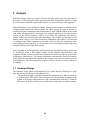
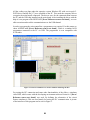
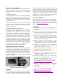
Figure 5: Proteus 6.0 simulator was used to simulate and debug the FFS.
For testing the I2C connection and some other functionalities of the slider, a simulator
called ISIS, which comes with the developing environment software Proteus 6.0 [Error!
Reference source not found.] was used. By defining the schematics of the circuit
Proteus simulates it. This was used mostly for testing the I2C communication. A picture
of the interface of this program can be seen in Figure 5.
26
5.2 Integration and Test
After each cycle of implementation the integration was tested, because much of the codes
from different parts were directly connected to each other. This was due to the fact that
the design consisted of several layers several layers with communication protocols
between each two layers. Therefore it was essential to find out partly whether the
hardware was working as it should and partly make sure that the communication
protocols were free of bugs as soon as possible.
To test the functionality different methods and programs were used.
• To check the functionality of the slider different test codes were tested for checking
the movement of the slider. Some hard coded tricks were also used to make sure that
the AD conversion was working correctly. When an error was detected, with help of
multimeter and oscilloscope the bug was found and fixed.
•
To test the I2C communication the Proteus program was used. Loading the HEXcodes in the program you can see all the elements of the I2C communication. The
start, stop, acknowledgement and values sent over the I2C channel are presented in a
structured way.
Unfortunately because of some bugs in the Proteus program for handling the I2C
communication, discovered late in the testing process, we had to do the testing using
other methods. The final method used was to fix the USB communication and send
the I2C data over the USB to be able to debug the I2C communication protocol.
•
Testing the USB communication protocol was done with help of the program
D2XXAPP. This program showed all the data received over the USB channel in a
terminal window. This way the communication could easily be checked. This
program also helped debugging the I2C protocol as stated in the previous bulletin.
•
Testing the API was done by developing an application. The application was made in
the scope of another master thesis running in parallel with this one. The main goal of
the application was to create remote collaboration using the force feedback sliders. In
this application two main boards with sliders connected to each were connected to
two different computers. The movement and force of each slider was then transferred
to another slider on the other computer. The results of that project are available on the
report of that thesis [13].
5.3 Problems
During the implementation process we encountered several problems. Due to the
complexity of the system and lack of debugging environments some of the problems took
a long time be found. Some of the problems have already been mentioned. Most of them
have already been solved but there were some problems that still exist and will be solved
in the future. The problems are listed below:
27
•
Reading user force: As mentioned before the calculation of the user force was if not
impossible but very hard task with the current design. This is being worked on and
will be fixed in the next version of the slider.
•
Instability in USB connection: In the initialization of the main board there is some
instability with the USB connection. This causes that the system should be restarted
some times in order to function properly. This problem is because of the overflow of
information in the USB channel. This can even occur under the run-time but it does
not create any problems. This noise can be corrected but due to the lack of time it still
exists in the current prototype.
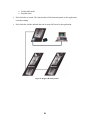
5.4 Final product
The system existing today is shown in Figure 6 and has the following properties:
•
The system consists of a main board and up to 16 sliders connected to it. This number
can easily be many more and even up to 128 if the power supply supports that number
of sliders.
•
The main board is connected to the computer via USB.
•
The system is OS-independent since the API is written in Java and can be run by Java
virtual Machine. The drivers for the USB communication are available for most of the
operative systems.
•
The sliders can operate with different forces and dynamically change to other forces
during run-time.
•
The force and position are available as input and output for each and every slider in
the system.
•
The operation delay is not noticeable with the sense of touch. The movements and
forces are smooth and continuous. The sliders operate with frequency 6.1 KHz.
•
The system is stable, besides the problems mentioned in the problems sections, and
independent of any external settings on the computer it is connected to.
•
The API provided is standard and easy-to-use.
•
The sliders can easily cooperate and affect each others performance characteristics
without creating any noticeable delay.
•
The following force functions should be available
o User mode
o Function mode with polynomial function of second degree.
28
o Lookup table mode
o Program mode
•
Each slider has a button. The functionality of this button depends on the application
currently running.
•
Each slider has a diode onboard that can be turned off an on by the application.
Figure 6: Design of the final product
29
6 Conclusion
The project was started with the goal to create a tangible user interface with force
feedback that was easily programmed to simulate different force functions. The final
product fulfils all the primary goals although it sometimes has stability problems during
start-up. The problems of the product have been discussed in a separate section.
The project started as an attempt to improve an existing proof of concept analogue system
developed in T2I lab. After carefully analyzing the options and solution, a fully digital
platform was decided to be built. The hardware consisted of a main board with an
ATMEGA8 microcontroller onboard and several sliders that are connected to the board.
The sliders have a slider board with a microcontroller onboard dedicated to take care of
the movement and communications of the unit.
The slider boards are connected via an I2C communication channel to the main board.
Via this channel the order are delivered to the slider and the current status of the slider is
reported to the board. The board tracks the changes in the sliders and reports them to the
computer via a USB cable. On the computer there is an application running that receives
these changes and sends commands back via the same channels to the sliders accordingly.
On the computer an API is designed to make the development of applications easier. This
API is made in Java for maximum platform independency. The API provides an easy to
use interface for programmers.
The software system was designed in several steps. After the final design of the hardware
was done a study was made on the structure of the system. The design of the system was
made in several layers as described. To make the testing and integration easier the
implementation was divided into several steps. After each step a complete test and
integration phase was performed to make sure all the new and old functionality were
operating. After completing all the steps some simple final test programs were made to
test the whole system. A larger application was also made in the scope of another master
thesis.
In conclusion the final product of the project is a set of stable force feedback sliders.
These sliders can be used for developing different application in which the extra
information using the tactile sense is desired. The wide range of use is stretched from
simple education application to very complicated remote controlling machines in
industrial factories.
30
6.1 Future work
The aim of this project has mostly been research in the area of force feedback in human
computer interactions. Therefore most of the effort in the project was laid on testing the
different possibilities and opportunities in the area rather than creating a commercial
product. This has leaded us to a final product that is not necessarily optimized and
stabilized as a product to be distributed widely. In order to improve the reliability factor
of the prototype the following improvements are suggested:
•
Improve reading of user force by changes in hardware and software.
•
More stable USB connection during start-up and avoiding overflows and collisions in
the USB data traffic.
•
Program the microcontrollers via the existing USB connection instead of using a
special programmer for better upgrade possibilities.
•
Handle I2C slave addressing of the sliders in a dynamic way for better modularity.
31
7 References
1. Minsky, M., Ouh-young, M., Steele, O., Brooks, F.P., and Behensky, M., ”Feeling
and seeing: issues in force display”,: Proc. of SI3D '90, ACM, 1990, pp. 235-243.
2. [Anon.] Available: http://www.phidgets.com/ (10 March 2007)
3. Rafael Ballagas, Meredith Ringel, Maureen Stone and Jan Borchers (2003) iStuff: A
Physical User Interface Toolkit for Ubiquitous Computing Environments.
4. Adjan Kretz, Remo Huber and Morten Fjeld, (2004) Force feedback slider (FFS):
Interactive device for learning system dynamics
5. Adjan Kretz, Remo Huber and Morten Fjeld, (Januari 2004) Force-feedback Human
Interactiv Device
6. [Anon.] Available: http://en.wikipedia.org/wiki/Audio_stream_input_output (10
March 2007)
7. [Anon.] Available: http://www.steinberg.de/324_1.html (10 March 2007)
8. [Anon.] Available:
http://www.atmel.com/dyn/resources/prod_documents/doc2486.pdf (10 March 2007)
9. [Anon.] I2C. Available: http://en.wikipedia.org/wiki/I2C (10 March 2007)
10. [Anon.] Available: http://en.wikipedia.org/wiki/Pulse-width_modulation (10 March
2007)
11. [Anon.] Available: http://en.wikipedia.org/wiki/USART (10 March 2007)
12. Julio Jenaro (2007), Digital Force Feedback Slider: Hardware Design and
Implementation
13. Martin Schrittenloher, (2007) Haptic Support for Remote Communication and
Collaboration: A modular framework for the Force Feedback Slider, LudwigMaximilians- University of Munich
14. [Anon.] Available: http://www.atmel.com/dyn/Products/tools_card.asp?tool_id=2725
(10 March 2007)
15. [Anon.] Available: http://www.eclipse.org/ (10 March 2007)
16. [Anon.] Available:
http://www.ftdichip.com/Projects/CodeExamples/OtherPlatforms.htm (10 March
2007)
32
17. [Anon.] Available: http://www.ftdichip.com/Drivers/D2XX.htm (10 March 2007)
18. [Anon.] Available: http://www.ftdichip.com/Projects/CodeExamples/C++Builder.htm
(10 March 2007)
19. [Anon.] Available: http://www.atmel.com/dyn/products/tools_card.asp?tool_id=3808
(10 March 2007)
20. [Anon.] Available: http://www.picbasic.org/proteus_vsm.php (10 March 2007)
33
Appendices
A - User Manual
This part is not published in the public version of the document. To get this information
please contact Ali Shahrokni or Morten Fjeld.
34
B - Communication protocols
This part is not published in the public version of the document. To get this information
please contact Ali Shahrokni or Morten Fjeld.
35
C – Conference Paper 1, 2006:
A. Shahrokni, J. Jenaro, T. Gustafsson, A. Vinnberg, J. Sandsjö, M.
Fjeld (2006): One-Dimensional Force Feedback Slider: Going from an
Analogue to a Digital Platform. Proc. ACM NordiCHI 2006, pp. 453456.
36
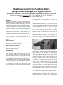
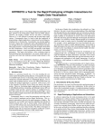
One-Dimensional Force Feedback Slider:
Going from an Analogue to a Digital Platform
Ali Shahrokni, Julio Jenaro, Tomas Gustafsson, Andreas Vinnberg, Johan Sandsjö, Morten Fjeld
Tabletop Interaction Lab (www.t2i.se), IDC, CSE, Chalmers TH, SE-412 96 Göteborg
{ali, julio, tomas, andreas, johan, morten}@t2i.se
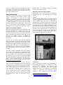
ABSTRACT
This paper examines the use of motorized physical sliders
with position and force as input and output parameters for
tangible human computer interaction. Firstly, we present
an analogue platform. It was used to realize two proof-ofconcept applications: one for learning system dynamics
as part of physics education and the second for
interaction with music loops. Based on the insight gained
with the analogue platform and the two applications, we
took the first steps towards a digital platform, also
presented here. More generally, the paper presents socalled haptic modes, which may be generated using force
feedback control of motorized sliders. The paper also
briefly presents parts of the underlying software and
hardware which was designed and realized as part of this
project.
and the feedback is mostly simulated by vibrations of
different frequency and intensity.
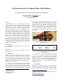
To explore a wider use of force feedback with onedimensional motorized sliders, we have started a project
called Force Feedback Slider (FFS). Motorized physical
sliders with position and force as input and output
parameters lend themselves well to tangible interaction
(Fig. 1). Their capacity to support direct [7] tangible
interaction can be proved at several levels. While the
directness of 3D interaction has been widely explored,
there is a need for more direct interaction with
multivariate models. For instance, the externalization of
abstract mathematical models was studied by Tweedie et
al. [8], as they examined a yield enhancement function of
upper and lower bounds.
Author Keywords
HCI, User interface design, physical prototyping, haptic
interface, force feedback, slider, TUI
ACM Classification Keywords
H.5.2 User Interfaces: Tangible user interfaces (TUI),
Haptic interface, prototyping
Figure 1. Motorized slider (left) and application (right).
INTRODUCTION
It is known that human beings have a very fast operating
sense of touch [1] and several research projects [2][3]
have capitalized on this fact. Interactive systems with
motorized sliders have been suggested in the iStuff [4]
and Phidgets [5] projects, as well as in commercial
joysticks with force feedback. Haptic display for socalled 3D haptic widgets has been examined [6]. Most of
the existing approaches have proposed motorized sliders
for output only, with no dynamic control of output force
or registration of user input force. These devices with
force feedback are not attuned to human tactile sensing
From a human’s perceptual point-of-view, the absence of
tactile feedback in GUI interfaces may overload our
visual senses and lead to increased physical strain. While
GUI input is largely limited to discrete operations such as
typing and selecting, a mouse affords some degree of
continuous control. However, since mouse interaction
occurs mainly without physical resistance and tactile
response it is not very effective. End-users who draw,
sculpt, or create continuous audio lines for long periods
of time using a mouse often become frustrated and
experience pain. There are negative health consequences
to the fixed posture and small repetitive movements
required by working with a GUI interface [3]. We admit
that one-dimensional sliders will not solve this problem.
However, the combination of alternative task-specific
UIs, including actuated sliders, may be an improvement.
The next section presents an analogue FFS platform,
including its software, followed by two proof-of-concept
applications and some discussion. This is followed by a
section on a digital FFS platform, including its hardware
and software. The final section discusses the results,
relates them to the other projects [4][5], and envisions the
next steps in the FFS project.
ANALOGUE PLATFORM
The first version of the FFS is a layered analogue system
which is connected to the computer through a USB
interface. The software is written in Java which
maximizes compatibility with different operating systems
and Java Applets. Using this device as a proof of concept,
two distinct applications were realized: the first for direct
interaction with a projectile motion model, Catapult (Fig.
2) [2], and the second for direct manipulation of sound
during playback in a program, FeelTheBeat (Fig. 3) [9].
Software of the Analogue Platform
The slider is designed in several layers which have been
previously described in a separate paper [10]. The
physical layer consists of an external USB sound card and
the slider board. The sound card is used to control the
slider board and send commands to the slider. It also
functions as an AD/DA converter. To stabilize the
movement of the slider a P-regulator is attached to the
slider board.
Machine. Thus the portability between the different
systems is successfully achieved.
Applications with the analogue platform
As mentioned in the previous sections, two applications
were realized to prove the functionality of the analogue
system.
Catapult 2
This is a secondary education (K-12) application allowing
for direct manipulation and testing of a catapult (Fig. 2).
Physics education often relies on the visualization of
theoretical laws to enhance the learning experience, and
while Java animations are widespread, they generally lack
user interaction. So, FFS could be advantageous to any
application used to interact with the law of physics. Here,
the users receive both tactile and visual feedback using
the software. We conjecture that a UI calling upon two
perceptual channels at the same time may help users to
more easily construct a mental model of the subjectmatter content. This application used the API.
The driver layer is in direct contact with the sound card
and sends and receives the commands directly from the
analogue hardware. Depending on which haptic mode1
the application requests a slider to run, the driver uses
different lookup tables (LUT) to control the behavior of
the slider. Each LUT contains the force to be applied by
the slider depending on the user force and the position of
the slider.
The slider should be compatible with major operating
systems and be easy to develop new applications for. To
achieve this goal an application program interface (API)
layer is provided in Java. This API allows the writing of
an application for the FFS without any knowledge of how
the slider fundamentally works. Most operating systems
support Audio-Class-USB and have available device
drivers. Also, the API is executable in the Java Virtual
1
FFS offers five haptic modes: In position, the slider is used only as
input device, the motor is switched off, and the user can move the slider
without FF. In elasticity, a default position and a variable resisting force
are defined. The user’s fingers have to overcome the resisting force.
When the handle is released it returns to the default position. Gradual
offers a number of discrete steps into which the handle can snap. In
texture, high-frequency low-intensity vibrations are applied to the
handle, thus giving users an impression of a rough surface. In
oscillation, the handle comes to rest after a damped sine movement.
These five haptic profiles are abstract descriptions of elementary
capacities; other applications can be composed from these modes. Any
finite function that can be written as a mathematical expression is
allowed [2].
Figure 2: The FFS in operation with catapult.
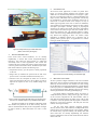
FeelTheBeat 3
This is an application allowing for direct manipulation of
sound during playback (Fig. 3). Computers are widely
used in music performance and production. DJs
increasingly use computers rather than analogue
turntables and mixers [11]. Musicians use sequencing
software in composition and ubiquitously employ
computers in their productions. Sequencing software
2
3
http://www.t2i.se/pub/media/ShootingDemo.avi
http://www.t2i.se/pub/media/FeelTheBeat.mpeg
offers the ability to arrange and transform music,
primarily in an offline situation, but with notable
exceptions such as Ableton Live, which is designed for
live performance. The aim of this application is to
develop a tangible user interface for common sequencing
operations such as the looping of a sound. Samples of
duration between 1 to 8 beats corresponding to 0.5 to 8
seconds are used in this case. The interface allows the
display and modification of sound during playback and
should operate in a direct way [7]. Furthermore, the slider
moves with different accelerations depending on the
amplitude of the sound that is played, generating different
perceivable forces. The proposed interface employs a
loudspeaker and a motorized slider [12] [9], thus offering
continuous audio, visual, and haptic cues during
playback. The slider handle moves according to a
predefined temporal audio parameter and thus gives
immediate and continuous feedback corresponding to the
current playback state. When the user holds or moves the
handle, the audio parameter changes and the audio
playback is altered accordingly. As the sound software
applied here was written in C++, this application
communicated directly with the sound card, bypassing the
Java API.
Figure 3. Amplitude envelope of sound and slider position.
Analogue platform: discussion
The analogue slider proved the validity of the idea. By
implementing a prototype system and testing its
operation, the way for improving the system opened up.
However, the analogue system exhibited a high latency
due to the fact that the data was processed through the
operating system, an external sound card, and the slider
board. Conversion between analogue and digital data and
the operating system’s sound mixer were responsible for
the largest parts of the delay. The design was not
sufficiently stable and depended on low-level operative
system settings. Nevertheless, the analogue platform
served as proof-of-concept. The next step was digitalizing
the system and combining several sliders to perform a
task.
DIGITAL PLATFORM
Based on previous experience and project aims, we
formulated a set of use requirements for the digital FFS
platform: i) low latency, ii) high stability, iii) platform
independency, iv) extendable to maximum of 16 sliders
mounted into a compact box, v) programmable via a
standardized API, vi) remote haptic collaboration
enabled.
The goal of digitalizing the system was to preserve its
advantage, solve the shortcomings presented above, and
thereby meet the use requirements. The most critical
problem is the high latency which causes the user to
experience the force change as discrete and not
continuous. Another major problem is system instability.
An additional requirement is to make the system
independent of operating system configurations and
settings. The digital solution is still under construction
but the tests conducted so far have shown promising
performance and much shorter delays. In the following
section we present and discuss hardware and software
issues of the digital platform.
Hardware of the digital platform
The digital version of the slider is designed in a modular
way and each slider can operate either individually or
within a combination of several sliders. Each slider has a
µcontroller operating at a clock frequency of 16 MHz. It
has several ADC converters digitalizing the analogue data
much faster than the sound card in the analogue version.
This reduces the latency of the slider considerably as
compared to the analogue system. The discreteness
should be undetectable by the human sense of touch.
The platform should allow the simultaneous operation of
several sliders side by side (Fig. 4). If each slider was
directly connected to the computer it would complicate
the system and increase the latency. Therefore, a
mainboard was designed that can control up to 16 sliders
simultaneously. It operates with the same kind of
µcontroller as each slider and at the same frequency. The
mainboard and the sliders are connected by an I2C bus
[13] which operates at a frequency of 400 KHz. The
sliders operate independently and therefore the bus is
only used to read the force or position of each slider or to
send LUTs to each slider. Thus, the amount of data
transferred by the bus is relatively low and should not
slow down the sliders.
Using in-house designed technology, the µcontroller
which drives the slider motor is able to determine
approximate forces applied by the user's hand and to
generate different resisting or active/driving forces. A
specific force is generated by sending the corresponding
current to the slider motor.
Software of the digital platform
Similar to the analogue design, the digital design has two
different layers of software: the µcontroller code and the
API code, which is the interface for the application
developer.
µcontroller programming
Each slider has a LUT stored in its memory according to
which it operates. Depending on the position of the
handle and some other factors, the slider generates a
specified force by applying the suitable current required
by the slider motor.
The mainboard µcontroller keeps track of the current
position and force of each slider. It can also send a new
LUT to the sliders using the I2C bus whenever a slider’s
operating mode changes.
Application Programming Interface (API)
As in the analogue version, the API simplifies the
development of new applications. Due to the same
reasons mentioned for the analogue system, the API is
written in Java. To make its use easier, the API inherits
the standard class (component) JSlider [14] which is the
standard soft slider class in Java library. To program, the
developer either chooses a standard operation mode or
provides a force function to be simulated by the slider.
The slider can either be resistive, active/driving, or both.
This means that it may resist against the user force (up to
a certain level given by the motor used), automatically
move with different forces, or combine these two
depending on the position of the slider handle.
Digital platform: discussion and outlook
We have achieved positive results in the design and
realization of the digital platform. In the next steps, we
foresee improvements in usability and robustness of the
hardware, the protocol, and the API. We also intend to
examine system performance related to human perceptual
factors such as haptic profile resolution, system feedback,
latency, and stability.
interface, modularity, and use of physical sliders are or
will be offered by the FFS. In contrast to commercial
joysticks with force feedback, FFS is planned to offer
accurate customized force feedback matching real world
settings, such as mechanics and music, more realistically.
In summary, we expect the FFS to be a versatile force
feedback device for developers and end-users.
ACKNOWLEDGEMENTS
Analogue platform realized by Adjan Kretz and Remo
Huber. FeelTheBeat realized with Tue Haste Andersen.
Sliders partly sponsored by Fournier Electronic (CH).
Thanks to http://www.eta.chalmers.se for cooperation and
support in hardware assembly.
REFERENCES
[1] Verplank, B., Gurevich, M., and Mathews, M., “The
PLANK: Designing a simple haptic controller”, Proc. of
NIME, 2002.
[2] Kretz, A., Huber, R., and Fjeld, M., “Force Feedback
Slider: An interactive device for learning dynamic system
behavior”, Proc. ICALT05, 2005, pp. 457-458.
[3] MacLean, K.E., Shaver, M.J., and Pai, D.K., “Handheld
Haptics: A USB Media Controller with Force Sensing,”
Proc. Symp. on Haptic Interfaces for Virtual Environment
and Teleoperator Systems, 2002, pp. 311-318.
[4] Ballagas, R., Ringel, M., Stone, M., and Borchers, J. 2003.
“iStuff: a physical user interface toolkit for ubiquitous
computing environments”, Proc. of CHI '03. pp. 537-544.
[5] Greenberg, S. and Fitchett, C. 2001. “Phidgets: easy
development of physical interfaces through physical
widgets”, Proc. of UIST '01, pp. 209-218.
[6] Miller, T. and Zeleznik, R. 1999. „The design of 3D haptic
widgets”, Proc. SI3D '99. ACM, pp. 97-102.
[7] Shneidemann, B., Designing the User Interface, 1993.
[8] Tweedie, L., Spence, R., Dawkes, H., and Su, H.
“Externalizing Abstract Mathematical Models”, Proc.
CHI96, 1996, pp. 406-412.
[9] Andersen, T.H., Huber, R., Kretz, A., and Fjeld, M. (2006).
“Feel the Beat: Direct Manipulation of Sound during
Playback”. Proc. TableTop2006, pp. 123-124.
[10] Kretz, A., Huber, R., and Fjeld, M., “Architecture of force
feedback slider”, ETH E-Collection, 2005. Available at
http://e-collection.ethbib.ethz.ch/show?type=semarb&nr=65
[11] Beamish, T., Maclean, K., and Fels, S. “Manipulating
Figure 4. Mock-up of multi-slider interactive device (left)
and the same mock-up device in use (right)
SUMMARY
We have presented an analogue and a digital realization
of the Force Feedback Slider (FFS). Most of the features
offered by iStuff [4] and Phidgets [5] such as USB
music: multimodal interaction for DJs”, Proc. CHI, 2004,
pp. 327-334.
[12] Newton-Dunn,
H., Nakano, H., and Gibson,
“BlockJam”, Abstract, Proc. SIGGRAPH, 2002.
[13] http://www.esacademy.com/faq/i2c/general/i2cproto.htm
[14] http://java.sun.com/j2se/1.4.2/docs/api/javax/swing/JSlider.html
J.,
D – Conference Paper 2, 2007:
J. Jenaro, A. Shahrokni, M. Fjeld (2007): One-Dimensional Force
Feedback Slider: Digital platform. In Proc. Workshop at the IEEE
Virtual Reality 2007 Conference: Mixed Reality User Interfaces:
Specification, Authoring, Adaptation (MRUI07), pp 47-51.
41
One-Dimensional Force Feedback Slider: Digital Platform
Julio Jenaro Rodríguez, Ali Shahrokni, Martin Schrittenloher, Morten Fjeld
TableTop Interaction Lab (http://t2i.se/), CSE
Chalmers University of Technology
Gothenburg, Sweden
ABSTRACT
This paper examines the use of motorized physical sliders with
position and force as input and output parameters for tangible
computer interaction. We have designed a device with the purpose
of controlling, in real time, a motor which is integrated into a
slider system with accuracy and latency values sufficient for
productive interaction. This was accomplished with a
microcontroller that handles the I2C protocol for communication
with a master device that centralizes the sliders’ information. The
system is modular, using the configuration of one mainboard and
I2C protocol to communicate with the sliders. The mainboard
interacts with the computer through a USB connection. The
mainboard also controls the sliders, each sitting on a slider board.
This paper also presents the designs and realizations of the
mainboard and slider board hardware components. Finally, the
paper envisions future applications of force feedback sliders such
as mapping of GUI sliders onto physical sliders, polling of user
impressions based on non-verbal selections cues, and remote
controls with haptic feedback.
may give users an added feeling of interaction with a real system.
This insight has been utilized in various fields such as tele-surgery
[12][6], digital media, and space station maintenance. Aiming to
explore a wider use of force feedback, we carried out a project
called Force Feedback Slider (FFS) 1 in which motorized physical
sliders are used to interact with users, utilizing position and force
as the main factors to achieve dynamic control (Figure 1). At the
same time, we read these values from the device to record the
user’s reaction.
Figure 1. Motorized slider (left) and mock-up box of multi-slider
interactive device (right).
Author Keywords:
Force feedback slider, digital hardware, haptic display, PID,
PWM, lookup table
Index Terms:
H.5.2 User Interfaces, Physical user interfaces, Haptic user
interface, GUI
1
INTRODUCTION
Human beings base their relationship with their environment
primarily on visual sensing. When interacting with computers we
often overload this sense, it being the main channel for feedback.
To reduce the task load on the visual sense, we seek to utilize
alternative perceptual channels; here, the sense of touch. We only
seldom use this sense when interacting with computers despite its
capability of fast operation [1].
While direct 3D interaction/manipulation has been widely
explored, the directness of haptic interfaces has not, even though
it may be justified at several levels [14]. Indeed, several research
projects [7][9] have examined and proved the benefit of touch
sensing in human-computer interaction. The use of force feedback
[email protected]
[email protected]
[email protected]
[email protected]
Figure 2. The FFS is intended to bring real and virtual environments
closer, thereby bridging the left and right part of the Milgram
continuum [10].
The first versions of the system were based on an analog
control of the motor [1][7] and some applications were developed
to test the device, such as an educational physics application
simulating a catapult [7] and a real-time music-editing system
called FeelTheBeat [1]. Our current goal is to digitalize the device
and turn it into a more versatile and configurable platform. This
may enable the design of a variety of single and multi-slider
applications (Figure 1).
2
RELATED WORK
USB/MIDI state-of-the-art user interfaces for music editing like
the Behringer B-Control Fader BCF2000 [17] and the Mackie
Control [19] already offer touch-sensitive motorized sliders.
However, the driving force in such sliders cannot be controlled
1
The project web site offers video documentation and previous
papers from the FFS project:
http://www.t2i.se/projects/ff.php
since they are based on speed control. This type of control
employs a constant current, giving a constant torque. While such
control is sufficient for audio editing, we aim for a more generic
interface where force serves as feedback in user-system
interaction. Hence, the novelty of the presented FFS lies in its
capacity to control the driving force while at the same time
measuring the force applied by the user. While the system we
design offers most standard features of actuated sliders, we also
plan to support applications where force serves as an input-output
medium (Table 1). A goal of this project is to offer a versatile
platform to map GUI slider onto a set of FFSs and thereby to
achieve a higher degree of mixed reality interaction [10].
Table 1. Position-Force matrix plotting two state-of-the-art user
interfaces for music editing in relation to the FFS according to their
input and output capacities.
FORCE
OUT
POSITION
IN
3
OUT
IN
Behringer
Mackie
FFS
FFS
Behringer
Mackie
FFS
FFS
DIGITAL FORCE FEEDBACK SLIDER
The goal of digitalizing the system is to address a set of critical
issues in the analogue version while preserving the system’s
advantages. The first issue was the high latency, which caused
users to experience the force change as discrete and not
continuous. The second issue was the system's instability in
controlling the motor, which caused non-optimal movement
patterns. These two issues were particularly difficult to address at
the same time. The third issue was an over-dependency on
operating system configurations and settings. Also, the motor
control function in the analog system [7] was hardware based, and
therefore difficult to modify.
Based on previous experience with the analog FFS [13] and
on the project’s goals, we formulated a set of use requirements for
the digital FFS platform:
i)
low latency
ii)
high stability
iii)
easy access to update motor control function
iv)
platform independency
v)
extendibility to a maximum of 16 sliders mounted into
a compact box
vi)
programmable via a standardized API
vii)
remote haptic collaboration enabled
The digital solution is still under construction and the tests
conducted so far have yielded promising functionality and
reduced delay times. The following sections will discuss the
design of digital hardware realization, as we aim to fulfill all
seven use requirements.
3.1
Hardware of the digital platform
The purpose of the system is to control multiple motorized sliders
and obtain feedback measurements of position and force. To
create a modular system, we split the platform up into two types
of boards: one to regulate the motor (called a slider board) and
another one to coordinate the slider boards and communicate with
the computer (called the mainboard). In this way, the sliders
operate independently and the bus is used to read the force or
position of each slider and to send Look-Up Tables (LUT) to the
microcontroller in the slider board. One microcontroller
commands the mainboard and each slider board is then
commanded by its own microcontroller. For this project, we chose
to use the Atmega-8 microcontroller with a 16 MHz crystal. The
RISC architecture of this chip can reach up to 16 MIPS (million
instructions per second). This is fast enough to adequately control
the system since the motor runs at up to 20 KHz (according to the
Nyquist–Shannon sampling theorem).
A clock cycle in the microcontroller takes approximately 6
ns and the operation usually takes less than 10 cycles to execute,
resulting in approximately 60 ns for the operation’s execution.
This latency is considerably reduced compared to the analog
design and makes the discreteness imperceptible by the human
sense of touch. Additionally, the microcontroller has 8 integrated
AD converters which are very useful in reading the parameters of
the motor and thereby controlling it. Another important feature is
the Atmega-8’s ability to handle the I2C protocol used for
communication between the slider boards and the mainboard. A
description of the different subsystems is provided in the
following sections.
3.2
Mainboard
The device is connected through the USB to the computer for fast
data transmission and easy recognition by the operating system.
This design increases the communication speed and thus reduces
the latency experienced with the old analog platform [1][3][7]. To
accomplish this, the mainboard uses a USB driver chip
(FT232RL) to control the frame communication between the
microcontroller and the computer. One of the most advantageous
features of this integrated circuit is that it requires few external
components to work properly and has integrated the EEPROM
memory used to customize the device properties. The board is
supplied with the 9 volt power supply used for the TTL circuits
and the motors, reducing possible interferences as much as
possible. The main function of the board is depicted a block
diagram (Figure 3) followed by the current realization of the
mainboard (Figure 4).
2
Figure 3: Mainboard block diagram with I C serial bus.
Thanks to the Atmega-8 features and some additional
hardware, the mainboard is equipped to carry out I2C
communication with the sliders. This enables a running speed of
400 KHz, which amounts to very fast master-slave
intercommunication. This bus also allows a large quantity of
devices to be connected, enabling the control of devices that use
many sliders such as DJ mixing boards. However, in our case, the
system is designed and optimized to control up to 16 sliders in
small applications.
mainboard. The communication through the I2C bus is
characterized by the reduced number of wires to transfer data
(only two wires are needed) and data communication frequencies
of 400 kHz, thanks to the Atmega-8. A block diagram of the
system is shown in Figure 5.
2
Figure 5. Slider board block diagram with I C serial bus.
The microcontroller sends pulse width modulated
signals to the H-Bridge.
Figure 4. Current version of the mainboad.
For future applications, the slider platform also has a switch
to enable/disable the slider or make the slider execute another
function (it will be determined by software in the microcontroller
firmware). This switch is connected to the microcontroller
through an AD converter input. In the future, the switch may be
replaced by a pressure-sensitive button, which can then be read by
the AD converter.
3.3
Slider board
Each motorized slider is controlled by an electronic board
attached to its base. We chose to have one microcontroller per
motor rather than one central board controlling all the motors
because this solution is more modular and the microcontrollers
can better control each motor. Furthermore, this helps achieve the
desired stability as described in use requirement ii.
In order to identify the devices, each slider board is defined
by a unique memory address. This allows the mainboard to
communicate directly with each of the sliders’ microcontroller.
In order to control the system, the microcontroller needs to
measure the position and electric current. To measure the position,
we use a potentiometer incorporated into the slider. A constant
voltage is supplied to it, making it so that when the position
changes the output resistance also changes, and with it the output
voltage to be measured by one of the microcontroller’s AD
converters. A similar process measures the current by
transforming the motor’s output current. In order to drive a small
motor in the forward and reverse directions we need an H-bridge
configuration, which basically consists of four transistors that
redirect the current in the desired direction. We used an integrated
circuit for its following properties: greater stability, its minimizing
of the differences between the transistors, reduced dimensions, a
wide range of operating voltage (5-36 V), TTL/CMOS compatible
inputs, faults status reporting, and current feedback output.
• Position: the slider is used only as an input device, the motor is
switched off, and the user can move the slider without force
feedback (FF).
The control of the motor is achieved using PWM signals
(Pulse Width Modulation) to control the voltage supplied and with
it, the torque (which is proportional to the current). This PWM
can be done in different ways. We used a fixed frequency of 10
kHz, generated with the microcontroller timer with a variable
on/off cycle. With this configuration, the number of PWM duty
cycles equals the average voltage over the motor, allowing us to
achieve different speeds in the motor and control the current.
Each slider board will function as a slave device, working in
a parallel process and waiting for petitions or orders from the
The slider platform is designed to memorize LUTs of 256
bytes for position and 256 bytes for force. With these LUTs, the
slider is able to perform these different functions:
• Elasticity: the user’s fingers must overcome a force which
increases with distance to default position. When the handle is
released it returns to its default position.
• Detents: offers a number of discrete steps into which the handle
can snap.
• Texture: high-frequency, low-intensity vibrations are applied to
the handle, giving users the impression of a rough surface.
• Oscillation: the handle comes to a rest after a damped sine
movement.
These five haptic profiles are abstract descriptions of
elementary capacities; other applications can be composed from
these modes. Any finite function that can be written as a
mathematical expression is allowed [8]. The first design and the
final slider are shown in Figure 6.
5
SCENARIOS OF USE
We envision several applications, of which we present three.
Firstly, we envision mapping Graphical User Interface (GUI)
sliders onto a set of FFSs incorporated into a box (Figure 1, right).
One use of such mapping could be in a financial modeling GUI
(Figure 8). Here, FFS detents with varying number of levels may
be programmed to provide haptic information about level of
interest rate or amount invested. In this example, we hope to
address typical ergonomic issues such as visual over-stimulation,
strain symptoms in repeated mouse movements, and lack of direct
and haptic input-output. Secondly, polling of physiological
sensation in test subjects may benefit from haptic representation
of non-verbal levels between upper and lower bounds such as
warm/cold, long/short time, and long/short distance. Finally,
remote controls involving multidimensional degrees of freedom
may benefit from mapping on FFSs. For instance, haptic
information of imminent collision risk or supportive cues in
grabbing remote physical objects are applications we consider
inviting for further investigation.
Figure 6. Testing board (top) and final slider board
(bottom, here held by two fingers).
4
ONGOING IMPLEMENTATION
From several motor control alternatives, we are currently
implementing a discrete PID control (Proportional-IntegralDerivative). This control was chosen because it is widely and
successfully used in control applications. This control also
prioritizes the precise output of the reference values below (Figure
7 shows a general case for PID control). The different parts of the
PID control actuate the system in the following ways:
• Proportional term (P): gives the system a control proportional
to the error.
• Integral term (I): stabilizes the system from the sum of the
previous errors. It is useful to eliminate the stationary error.
• Derivative term (D): anticipates the future error so that the
output is proportional to the error’s rate of change over time. It
improves the response if there is any sudden change in the
system.
Figure 7. Close Loop System with PID where y0 is reference input,
e is error, u is controller output, and y is desired system output.
Each microcontroller has an automatic recalibrating system
that calculates the parameters of the PID at startup. Thus, the
slider is controlled with the same precision irregardless of changes
in friction caused by slider deterioration over time or other
factors.
Figure 8. GUI for financial modeling, with soft sliders [20].
6
DISCUSSION AND OUTLOOK
We have presented a digital realization of the Force Feedback
Slider (FFS). This new platform contains almost all of the features
offered by the state-of-the-art user interfaces for music editing
like the Behringer B-Control Fader BCF2000 [17] and the Mackie
Control [19] such as a USB/MIDI interface, modularity, and the
use of actuated physical sliders. Related research projects offering
actuated physical sliders are iStuff [2] and Phidgets [5].
Our digital platform considerably reduces the latency as
compared with our previous, analog version [1][7]. We now use
an AD converter integrated into the microcontroller, which is
faster than the soundcard used in the analog version. Only an API
is needed to control the platform and the program to control the
functions is in the motor’s firmware. The delay has also been
reduced, increasing the stability.
The five basic haptic functions suggested (position,
elasticity, detents, texture, and oscillation) are implemented in the
firmware of the microcontroller and not in the computer, making
for reduced latency, improved stability, and thereby faster and
easier control. We are currently implementing new functions
based on combinations of the five basic functions that the slider is
able to work with.
The haptic device has an enable/disable button and a LED
which is able to indicate a predefined binary slider status, hence
making the status visible to the user.
Finally, we have shown some future applications of the FFS
such as the mapping of GUI sliders onto FFSs, polling of user
impressions based on non-verbal selections, and a remote control
with haptic warning cues. We even envision further uses, such as
remote collaboration, educational uses, 3D graphics control,
multi-factor optimization, music applications, collaborative
editing [15], interpersonal communication [11], and haptic
alphabets [4].
ACKNOWLEDGEMENTS
Sliders were partly sponsored by Fournier Electronic (CH).
Thanks to Olga, Olivier, Selina, and Martin for the help during the
project. Thanks to http://www.eta.chalmers.se/ for cooperation
and support in the slider production.
REFERENCES
[1] Andersen, T.H., Huber, R., Kretz, A., and Fjeld, M., "Feel
the Beat: Direct Manipulation of Sound during Playback ",
Proc. TableTop 2006, IEEE, pp. 123-124, 2006.
[2] Ballagas, R., Ringel, M., Stone, M., and Borchers, J., "iStuff:
a physical user interface toolkit for ubiquitous computing
environments", Proc. CHI '03, ACM Press, pp. 537-544,
2003.
[3] Beamish, T., Maclean, K., and Fels, S., "Manipulating
music: multimodal interaction for DJs", Proc. CHI, pp. 327334, 2004
[8] Tweedie, L., Spence, R., Dawkes, H., and Su, H.,
"Externalizing Abstract Mathematical
CHI96, pp. 406-412, 1996.
Models",
Proc.
[9] MacLean, K.E., Shaver, M.J., and Pai, D.K., "Handheld
Haptics: A USB Media Controller with Force Sensing",
Proc. Symp. on Haptic Interfaces for Virtual Environment
and Teleoperator Systems, pp. 311-318, 2002.
[10] Milgram, P., Takemura, H., Utsumi, A., and Kishino, F.,
"Augmented Reality: A class of displays on the realityvirtuality continuum", SPIE: Telemanipulator and
Telepresence Technologies, Boston, MA, pp. 282-292, 1994.
[11] Oakley, I., Brewster, S., and Gray, P., "Can you feel the
force? An investigation of Haptic Collaboration in Shared
Editors", Proc. Eurohaptics 2001, pp. 54-59, 2001.
[12] Gorman, P. J., Lieser, J. D., Murray, W. B., Haluck, R. S.,
and Krummel, T. M., "Assessment and validation of a force
feedback virtual reality based surgical simulator", Proc.
Third Phantom User’s Group Workshop, Cambridge, MA,
1998.
[13] Shahrokni, A., Jenaro, J., Gustafsson, T., Vinnberg, A.,
Sandsjö, J., and Fjeld, M., "One-Dimensional Force
Feedback Slider: Going from an Analogue to a Digital
Platform", Proc. NordiCHI 2006, ACM Press, pp. 453-456,
2006.
[14] Shneiderman, B., Designing the User Interface, 1993.
[15] Snibbe, S.S., MacLean, K.E., Shaw, R., Roderick, J.B.,
[4] Brave, S., and Dahley, A., "inTouch: A Medium for Haptic
Verplank, W., and Scheeff, M., "Haptic Metaphors for
DigitalMedia", Proc. ACM UIST, 2001.
Interpersonal Communication", Proc. CHI, ACM Press, pp.
363-364, 1997.
[16] Verplank, B., Gurevich, M., and Mathews, M., "The
[5] Greenberg, S., and Fitchett, C., "Phidgets: easy development
of physical interfaces through physical widgets", Proc. UIST
'01, pp. 209-218, 2001.
[6] Shennib, H., Bastawisy, A., McLoughlin, J., and Moll F.,
"Robotic computer assisted telemanipulation enhances
coronary artery bypass", J. Thoracic Cardiovascular Surgery,
vol. 117, pp. 310–316, 1999.
[7] Kretz, A., Huber, R., and Fjeld, M., "Force Feedback Slider:
An interactive device for learning dynamic system
behavior", Proc. ICALT05, pp. 457-458, 2005.
PLANK: Designing a simple haptic controller", Proc. of
NIME, 2002.
[17] www.behringer.com/BCF2000/index.cfm?lang=ENG
[18] www.esacademy.com/faq/i2c/general/i2cproto.htm
[19] www.mackie.com/products/mcu/index.html
[20] www.macrofocus.com