1
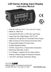
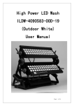
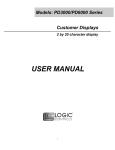
Model PD6200 Analog Input Rate/Totalizer
Instruction Manual
Transmitter Supply Voltage Selection (P+, P-)
1.
2.
3.
4.
All meters, including models equipped with the 12/24 VDC power
option, are shipped from the factory configured to provide 24 VDC
power for the transmitter or sensor.
If the transmitter requires 5 or 10 VDC excitation, the internal jumper
J4 must be configured accordingly.
To access the voltage selection jumper:
Remove all the connectors.
Unscrew the back cover.
Slide the back cover about 1 inch.
Configure the J4 jumper, located behind the input signal connector,
for the desired excitation voltage as shown.
Figure 5: Transmitter Supply Voltage Selection
Connections
All connections are made to removable screw terminal connectors
located at the rear of the meter.
Caution!
Use copper wire with 60°C or 60/75°C insulation
for all line voltage connections. Observe all
safety regulations. Electrical wiring should be
performed in accordance with all applicable
national, state, and local codes to prevent
damage to the meter and ensure personnel
safety.
19