1
Cisco IOS
Terminal Services
Configuration Guide
Release 12.2
Corporate Headquarters
Cisco Systems, Inc.
170 West Tasman Drive
San Jose, CA 95134-1706
USA
http://www.cisco.com
Tel: 408 526-4000
800 553-NETS (6387)
Fax: 408 526-4100
Customer Order Number: DOC-7812093=
Text Part Number: 78-12093-01
THE SPECIFICATIONS AND INFORMATION REGARDING THE PRODUCTS IN THIS MANUAL ARE SUBJECT TO CHANGE WITHOUT
NOTICE. ALL STATEMENTS, INFORMATION, AND RECOMMENDATIONS IN THIS MANUAL ARE BELIEVED TO BE ACCURATE BUT ARE
PRESENTED WITHOUT WARRANTY OF ANY KIND, EXPRESS OR IMPLIED. USERS MUST TAKE FULL RESPONSIBILITY FOR THEIR
APPLICATION OF ANY PRODUCTS.
THE SOFTWARE LICENSE AND LIMITED WARRANTY FOR THE ACCOMPANYING PRODUCT ARE SET FORTH IN THE INFORMATION
PACKET THAT SHIPPED WITH THE PRODUCT AND ARE INCORPORATED HEREIN BY THIS REFERENCE. IF YOU ARE UNABLE TO
LOCATE THE SOFTWARE LICENSE OR LIMITED WARRANTY, CONTACT YOUR CISCO REPRESENTATIVE FOR A COPY.
The Cisco implementation of TCP header compression is an adaptation of a program developed by the University of California, Berkeley (UCB) as part of
UCB’s public domain version of the UNIX operating system. All rights reserved. Copyright © 1981, Regents of the University of California.
NOTWITHSTANDING ANY OTHER WARRANTY HEREIN, ALL DOCUMENT FILES AND SOFTWARE OF THESE SUPPLIERS ARE PROVIDED
“AS IS” WITH ALL FAULTS. CISCO AND THE ABOVE-NAMED SUPPLIERS DISCLAIM ALL WARRANTIES, EXPRESSED OR IMPLIED,
INCLUDING, WITHOUT LIMITATION, THOSE OF MERCHANTABILITY, FITNESS FOR A PARTICULAR PURPOSE AND
NONINFRINGEMENT OR ARISING FROM A COURSE OF DEALING, USAGE, OR TRADE PRACTICE.
IN NO EVENT SHALL CISCO OR ITS SUPPLIERS BE LIABLE FOR ANY INDIRECT, SPECIAL, CONSEQUENTIAL, OR INCIDENTAL
DAMAGES, INCLUDING, WITHOUT LIMITATION, LOST PROFITS OR LOSS OR DAMAGE TO DATA ARISING OUT OF THE USE OR
INABILITY TO USE THIS MANUAL, EVEN IF CISCO OR ITS SUPPLIERS HAVE BEEN ADVISED OF THE POSSIBILITY OF SUCH DAMAGES.
AccessPath, AtmDirector, Browse with Me, CCIP, CCSI, CD-PAC, CiscoLink, the Cisco Powered Network logo, Cisco Systems Networking Academy,
the Cisco Systems Networking Academy logo, Cisco Unity, Fast Step, Follow Me Browsing, FormShare, FrameShare, IGX, Internet Quotient, IP/VC, iQ
Breakthrough, iQ Expertise, iQ FastTrack, the iQ Logo, iQ Net Readiness Scorecard, MGX, the Networkers logo, ScriptBuilder, ScriptShare, SMARTnet,
TransPath, Voice LAN, Wavelength Router, and WebViewer are trademarks of Cisco Systems, Inc.; Changing the Way We Work, Live, Play, and Learn,
and Discover All That’s Possible are service marks of Cisco Systems, Inc.; and Aironet, ASIST, BPX, Catalyst, CCDA, CCDP, CCIE, CCNA, CCNP,
Cisco, the Cisco Certified Internetwork Expert logo, Cisco IOS, the Cisco IOS logo, Cisco Press, Cisco Systems, Cisco Systems Capital, the Cisco Systems
logo, Empowering the Internet Generation, Enterprise/Solver, EtherChannel, EtherSwitch, FastHub, FastSwitch, GigaStack, IOS, IP/TV, LightStream,
MICA, Network Registrar, Packet, PIX, Post-Routing, Pre-Routing, RateMUX, Registrar, SlideCast, StrataView Plus, Stratm, SwitchProbe, TeleRouter,
and VCO are registered trademarks of Cisco Systems, Inc. and/or its affiliates in the U.S. and certain other countries.
All other trademarks mentioned in this document or Web site are the property of their respective owners. The use of the word partner does not imply a
partnership relationship between Cisco and any other company. (0110R)
Cisco IOS Terminal Services Configuration Guide
Copyright © 2001, Cisco Systems, Inc.
All rights reserved.
C O N T E N T S
About Cisco IOS Software Documentation
Documentation Objectives
Audience
xv
xv
xv
Documentation Organization
xv
Documentation Modules
Master Indexes
xv
xviii
Supporting Documents and Resources
New and Changed Information
Document Conventions
xix
xix
Obtaining Documentation
World Wide Web
xx
xx
Documentation CD-ROM
xx
Ordering Documentation
xxi
Documentation Feedback
xxi
Obtaining Technical Assistance
Cisco.com
xviii
xxi
xxi
Technical Assistance Center
xxii
Contacting TAC by Using the Cisco TAC Website
Contacting TAC by Telephone
Using Cisco IOS Software
xxii
xxiii
Understanding Command Modes
Getting Help
xxii
xxiii
xxiv
Example: How to Find Command Options
Using the no and default Forms of Commands
Saving Configuration Changes
xxv
xxvii
xxviii
Filtering Output from the show and more Commands
Identifying Supported Platforms
Using Feature Navigator
xxviii
xxix
xxix
Using Software Release Notes
xxix
Cisco IOS Terminal Services Configuration Guide
iii
Contents
Terminal Services Overview
TC-1
Cisco IOS Network Access Devices
Line Characteristics and Modems
TC-1
TC-2
Asynchronous Character Stream Calls
Remote Node Services
Terminal Services
Protocol Translation
TC-3
TC-3
TC-6
TC-6
Configuring Terminal Operating Characteristics for Dial-In Sessions
Terminal Operating Characteristics Overview
Selecting a Preferred Connection Protocol
Specifying the Transport Protocol
TC-9
TC-9
TC-10
Specifying a Local Transport Protocol
TC-10
Configuring Communication Parameters for Terminal Ports
Configuring Sessions on a Line
TC-11
TC-11
Configuring Local Session Parameters
TC-12
Changing the Default Privilege Level for Lines
Enabling Password Checking at Login
TC-13
Establishing Terminal Session Limits
TC-13
TC-12
Displaying Line Connection Information After the Login Prompt
Configuring Dial-In Terminal Services
Dial-In Terminal Service Overview
Configuring Telnet and rlogin
TC-14
TC-15
TC-15
TC-16
Telnet and rlogin Configuration Task List
Configuring Telnet and UNIX rlogin
TC-17
TC-17
Making Telnet and UNIX rlogin Connections
TC-19
Using UNIX Style Syntax for rlogin Connections
Monitoring TCP/IP Connections
Telnet and rlogin Examples
TC-9
TC-20
TC-20
TC-21
Telnet Connection Example
TC-21
Telnet Connection Without and With Messages Suppressed Example
rlogin Connection Example
TC-22
rlogin UNIX-Style Syntax Example
TC-22
Switch Between Telnet and rlogin Sessions Example
List Supported Telnet Commands Example
Using Cisco DialOut for Telnet Connections
Cisco IOS Terminal Services Configuration Guide
iv
TC-23
TC-23
TC-22
TC-21
Contents
Configuring Stream TCP
TC-24
Stream TCP Autocommand Procedure
Configuring LAT
LAT Overview
TC-24
TC-25
LAT Functionality
LAT Services
LAT Groups
TC-24
TC-25
TC-26
TC-26
LAT Sessions and Connection Support
Connecting a VMS Host Using LAT
TC-27
TC-27
VMS Version 5.4 or Earlier System
VMS Version 5.5 or Later System
TC-27
TC-27
Port Names When Configuring a LAT Printer
Additional LAT Capability
LAT Configuration Task List
TC-28
TC-28
TC-28
Configuring Basic LAT Services
Enabling Inbound Services
TC-29
TC-29
Controlling Service Announcements and Service Solicitation
Configuring Traffic Timers
Optimizing Performance
TC-31
TC-32
Defining LAT Access Lists
TC-32
Enabling Remote LAT Modification
Making LAT Connections
TC-33
TC-33
Monitoring and Maintaining LAT Connections
LAT Configuration and Connection Examples
Basic LAT Service Example
TC-34
TC-35
TC-35
LAT Service with Selected Group Codes Example
TC-35
Displaying LAT Services on the Same LAN Example
Establishing an Outbound LAT Session Example
TC-36
TC-36
Logically Partitioning LAT Services by Terminal Line Example
LAT Rotary Groups Example
LAT Connection Examples
TC-36
TC-36
Associating a Rotary Group with a Service Example
LAT Access List Example
TC-30
TC-37
TC-37
TC-38
Cisco IOS Terminal Services Configuration Guide
v
Contents
Configuring TN3270
TC-39
TN3270 Overview
TC-39
Keymaps and ttycaps
TC-40
Startup Sequence Priorities
TC-41
Using the Default Terminal Emulation File to Connect
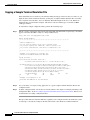
Copying a Sample Terminal Emulation File
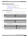
TN3270 Configuration Task List
TC-44
TC-45
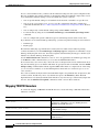
Configuring TN3270 Connections
Mapping TN3270 Characters
Starting TN3270 Sessions
TC-45
TC-46
TC-47
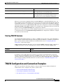
TN3270 Configuration and Connection Examples
TC-47
Custom Terminal Emulation File Example
TC-48
Custom Keyboard Emulation File Example
TC-48
Line Specification for a Custom Emulation Example
Character Mapping Examples
TC-49
TN3270 Connection Example
TC-50
Configuring XRemote
TC-43
TC-49
TC-50
X and the Client/Server Model
XRemote Overview
TC-51
Connection Capability
Remote Access to Fonts
TC-51
TC-52
XRemote Configuration Task List
Configuring XRemote
TC-50
TC-52
TC-53
Selecting Fonts for X Terminal Applications
TC-54
Accessing Nonresident Fonts Using TFTP
Selecting DECwindows Fonts
Making XRemote Connections
TC-54
TC-54
TC-55
Connecting Through Automatic Session Startup with an XDMCP Server
TC-55
Connecting Through Automatic Session Startup with a DECwindows Login via LAT
Connecting Through Manual XRemote Session Startup
Enabling XRemote Manually
TC-56
Connecting to the Remote Host Computer
Setting the Location of the X Display
Starting Client Applications
Returning to the EXEC Prompt
Cisco IOS Terminal Services Configuration Guide
vi
TC-57
TC-57
TC-57
TC-57
TC-56
TC-55
Contents
Reenabling XRemote Manually
TC-58
Establishing XRemote Sessions Between Servers
Exiting XRemote Sessions
TC-58
TC-59
Monitoring XRemote Connections
TC-59
XRemote Configuration and Connection Examples
Standard XRemote Configuration Example
TC-60
TC-60
Connecting Through Automatic Session Startup with XDMCP Server Example
TC-60
Connecting Through Automatic Session Startup with DECwindows Login via LAT Example
Enabling XRemote Manually Example
TC-60
Connecting an X Display Terminal Example
TC-61
Making XRemote Connections Between Servers Example
Configuring AppleTalk Remote Access
ARA Overview
TC-60
TC-61
TC-65
TC-65
ARA Configuration Task List
Connecting Cables
TC-66
TC-67
Configuring the Line and the Modem
Configuring ARA
TC-67
TC-68
Configuring ARA to Start Up Automatically
Configuring ARA Security
TC-70
ARA Server Security
TC-70
Local or Remote Security Database
TC-69
TC-71
TACACS and TACACS+ Security for ARA
TC-72
Enabling AAA/TACACS+ for ARA Authentication
TC-73
Connecting to an AppleTalk Network from a Client Running a Different Virtual Terminal
Protocol TC-76
Making ARA Connections
Monitoring an ARA Server
TC-77
TC-77
Monitoring the AppleTalk Network
TC-77
Troubleshooting ARA Connections
TC-78
ARAP Debugging Examples
TC-79
ARA Configuration and Connection Examples
ARA Server Configuration Procedure
TC-81
TC-81
Dedicated ARA Line with User Authentication Example
TC-82
Autostart Multiple ARA Lines with User Authentication Example
Telebit T-3000 Modem Setup Procedure
TC-82
TC-82
Cisco IOS Terminal Services Configuration Guide
vii
Contents
Modified and Unmodified CCL Scripts Sample Commands
ARA Router Support Example
TC-83
TC-84
Extended AppleTalk Network Example
Cable Range Expansion Example
TC-84
TC-84
Extended Network in Discovery Mode Example
TACACS Username Authentication Example
TC-85
TC-85
TACACS Enabled for ARA Authentication Example
TC-85
AppleTalk Network Connection over a Foreign Protocol Example
Configuring Support for NASI Clients to Access Network Resources
NASI Server Overview
TC-87
Configuring the Router as a NASI Server
TC-89
Configuring the Cisco PAD Facility for X.25 Connections
PAD Connection Overview
TC-91
Cisco PAD EXEC User Interface Connections
Cisco Universal X.28 PAD Emulation Mode
TC-93
TC-93
X.3 PAD EXEC User Interface Configuration Task List
Making a PAD Connection
Exiting a PAD Session
TC-94
TC-95
Monitoring X.25 PAD Connections
Setting X.3 PAD Parameters
TC-95
TC-95
X.28 PAD Emulation Configuration Task List
TC-97
Accessing X.28 Mode and Setting Options
Exchanging PAD Command Signals
Clearing a Call
TC-94
TC-94
Switching Between Connections
Placing a Call
TC-97
TC-98
TC-99
TC-100
Customizing X.3 Parameters
TC-100
Accepting Reverse or Bidirectional X.25 Connections
Setting PAD French Language Service Signals
In X.28 Mode
TC-101
Using an X.29 Profile
TC-101
Remote Access to X.28 Mode
TC-101
Using an Asynchronous Line
Using Incoming Telnet
Using Incoming X.25
Cisco IOS Terminal Services Configuration Guide
viii
TC-91
TC-102
TC-102
TC-103
TC-100
TC-100
TC-86
TC-87
Contents
Making X.25 PAD Calls over IP Networks
Configuring PAD Subaddressing
Configuring X.29 Reselect
TC-104
TC-104
Using Mnemonic Addressing
Character Limitations
TC-105
TC-105
Mnemonic Format Options
Example 1
TC-105
Example 2
TC-106
Example 3
TC-106
Example 4
TC-106
Facility Codes
PAD Examples
TC-103
TC-105
TC-107
TC-107
PAD EXEC User Interface Connection Examples
PAD Mode Connection Examples
TC-108
X.3 Parameter Customization Example
Load an X.3 Profile Example
TC-107
TC-108
TC-109
Set PAD Parameters Example
TC-109
Cisco Universal X.28 PAD Emulation Mode Examples
TC-111
Set Parameters Using X.28 PAD Emulation Mode Example
NUI Data Relocation Example
TC-111
X.25 Reverse Charge Example
TC-112
X.25 Call Detail Display Example
TC-111
TC-112
Set PAD French Service Signals in X.28 Mode Example
TC-112
Set PAD French Service Signals with an X.29 Profile Example
Get Help Example
PAD XOT Examples
TC-112
TC-112
TC-113
Accept XOT to PAD Connections Example
Accept XOT to Protocol Translation Example
TC-113
TC-113
Initiate a PAD Call over an XOT Connection Example
Address Substitution for PAD Calls Example
PAD Subaddressing Examples
TC-113
TC-113
TC-114
Configuring Protocol Translation and Virtual Asynchronous Devices
Protocol Translation Overview
TC-118
Definition of Protocol Translation
Definition of Tunneling
TC-117
TC-118
TC-119
Cisco IOS Terminal Services Configuration Guide
ix
Contents
Deciding Whether to Use One-Step or Two-Step Protocol Translation
One-Step Protocol Translation
TC-120
Two-Step Protocol Translation
TC-121
Tunneling SLIP, PPP, and ARA
TC-121
One-Step Tunneling of SLIP, PPP, and ARA
Two-Step Tunneling of PPP and SLIP
Two-Step Tunneling of ARA
TC-121
TC-122
TC-122
Setting Up Virtual Templates for Protocol Translation
Virtual Templates and L2F
TC-120
TC-122
TC-124
Protocol Translation Configuration Task List
TC-124
Configuring One-Step Protocol Translation
TC-124
Configuring a Virtual Template for One-Step Protocol Translation
Configuring Two-Step Protocol Translation
TC-126
Configuring a Virtual Template for Two-Step Protocol Translation
Changing the Number of Supported Translation Sessions
Configuring Tunneling of SLIP, PPP, or ARA
TC-125
TC-127
TC-127
TC-128
Configuring One-Step Tunneling of SLIP or PPP
Configuring One-Step Tunneling of ARA
TC-128
TC-129
Configuring Two-Step Tunneling of SLIP or PPP
TC-130
Enabling Dynamic Address Assignment for Outgoing PPP and SLIP on Virtual Terminal Lines
Assigning IP Addresses Using DHCP
TC-130
Assigning IP Addresses Using Local IP Address Pooling
Configuring X.29 Access Lists
TC-131
Creating an X.29 Access List
TC-132
Applying an Access List to a Virtual Line
Creating an X.29 Profile Script
Defining X.25 Host Names
TC-132
TC-132
TC-133
Protocol Translation and Processing PAD Calls
Background Definitions and Terms
Accepting a PAD Call
TC-131
TC-133
TC-133
TC-134
Accepting Incoming PAD Protocol Translation Calls
TC-134
Processing Outgoing PAD Calls Initiated by Protocol Translation
Increasing or Decreasing the Number of Virtual Terminal Lines
Enabling Asynchronous Functions on Virtual Terminal Lines
Creating Virtual Asynchronous Interfaces
Cisco IOS Terminal Services Configuration Guide
x
TC-138
TC-136
TC-137
TC-135
TC-130
Contents
Enabling Protocol Translation of PPP and SLIP on Virtual Asynchronous Interfaces
Enabling IPX-PPP over X.25 to an IPX Network on Virtual Terminal Lines
Enabling Dynamic Routing on Virtual Asynchronous Interfaces
Enabling Keepalive Updates on Virtual Asynchronous Interfaces
Enabling PAP
TC-139
TC-140
TC-140
Enabling PPP Authentication on Virtual Asynchronous Interfaces
Enabling CHAP
TC-138
TC-139
Enabling TCP/IP Header Compression on Virtual Asynchronous Interfaces
Setting an MTU on Virtual Asynchronous Interfaces
TC-141
TC-141
TC-142
Enabling PPP Authentication via TACACS on Virtual Asynchronous Interfaces
Maintaining Virtual Interfaces
TC-142
TC-142
Monitoring and Maintaining a Virtual Access Interface
Displaying a Virtual Asynchronous Interface
Monitoring Protocol Translation Connections
TC-142
TC-143
Troubleshooting Virtual Asynchronous Interfaces
TC-143
TC-144
Logging vty-Asynchronous Authentication Information to the Console Terminal
Logging vty-Asynchronous Authentication Information to a Buffer
Troubleshooting Protocol Translation
TC-144
TC-145
Logging vty-Asynchronous Authentication Information to a UNIX Syslog Server
TC-145
TC-145
Virtual Template for Protocol Translation Examples
One-Step Examples
TC-138
TC-145
TC-146
Tunnel PPP Across X.25 Example
TC-146
Tunnel SLIP Across X.25 Example
TC-146
Tunnel PPP Across X.25 and Specifying CHAP and Access List Security Example
Tunnel PPP with Header Compression On Example
Tunnel IPX-PPP Across X.25 Example
Two-Step Examples
TC-147
TC-147
TC-147
TC-147
Two-Step Tunneling of PPP with Dynamic Routing and Header Compression Example
Two-Step Tunneling of PPP with Dynamic Routing, TACACS, and CHAP Example
Protocol Translation Application Examples
Basic Configuration Example
TC-148
TC-148
TC-148
TC-149
Central Site Protocol Translation Example
TC-152
Decreasing the Number of Translation Sessions Example
Increasing the Number of Translation Sessions Example
LAT-to-LAT over an IP WAN Example
TC-153
TC-153
TC-153
Cisco IOS Terminal Services Configuration Guide
xi
Contents
LAT-to-LAT over Frame Relay or SMDS Example
TC-155
LAT-to-LAT Translation over a WAN Example
TC-157
LAT-to-LAT over an X.25 Translation Example
TC-158
LAT-to-TCP Translation over a WAN Example
TC-159
LAT-to-TCP over X.25 Example
TC-160
LAT-to-X.25 Host Configuration Example
Local LAT-to-TCP Translation Example
TC-162
TC-164
Local LAT-to-TCP Configuration Example
TC-164
Standalone LAT-to-TCP Translation Example
Tunneling SLIP Inside TCP Example
Tunneling PPP over X.25 Example
TC-166
TC-167
TC-167
X.25 to L2F PPP Tunneling Example
TC-168
Assigning Addresses Dynamically for PPP Example
Local IP Address Pool Example
X.29 Access List Example
X.3 Profile Example
TC-170
TC-170
TC-170
TC-171
X.25 PAD-to-LAT Configuration Example
TC-171
X.25 PAD-to-TCP Configuration Example
TC-173
Protocol Translation Session Examples
TC-174
One-Step Method for TCP-to-X.25 Host Connections Example
TC-175
Using the Two-Step Method for TCP-to-PAD Connections Example
Two-Step Protocol Translation for TCP-to-PAD Connections Example
Changing Parameters and Settings Dynamically Example
Monitoring Protocol Translation Connections Example
TC-175
TC-176
TC-177
TC-178
Two-Step Protocol Translation for Virtual Terminal Asynchronous Interfaces Example
Appendixes
X.3 PAD Parameters
TC-181
X.3 PAD Parameter Descriptions
TC-182
Parameter 1: PAD Recall Using a Character
Parameter 2: Echo
TC-182
TC-182
Parameter 3: Selection of Data Forwarding Character
Parameter 4: Selection of Idle Timer Delay
Parameter 5: Ancillary Device Control
TC-184
Parameter 6: Control of PAD Service Signals
Cisco IOS Terminal Services Configuration Guide
xii
TC-183
TC-184
TC-183
TC-178
Contents
Parameter 7: Selection of Operation of PAD on Receipt of a BREAK Signal
Parameter 8: Discard Output
TC-185
Parameter 9: Padding After Return
TC-186
Parameter 10: Line Folding (Not Supported)
Parameter 11: DTE Speed
TC-186
TC-186
Parameter 12: Flow Control of the PAD by the Start-Stop Mode DTE
Parameter 13: Line Feed Insertion
TC-187
Parameter 14: Line Feed Padding
TC-187
Parameter 15: Editing
Parameter 17: Line Delete
TC-188
TC-188
Parameter 18: Line Display
TC-188
Parameter 19: Editing PAD Service Signals
Parameter 20: Echo Mask
Parameter 22: Page Wait
TC-190
TC-191
TC-193
TC-193
Using Regular Expressions
TC-193
Creating Regular Expressions
TC-194
Single-Character Patterns
TC-194
Multiple-Character Patterns
Multipliers
TC-196
Alternation
TC-197
Anchoring
TC-189
TC-189
Parameter 21: Parity Treatment
General Concepts
TC-187
TC-188
Parameter 16: Character Delete
Regular Expressions
TC-185
TC-195
TC-197
Parentheses for Recall
TC-198
Regular Expressions Examples
Chat Scripts Example
TC-199
TC-199
X.25 Switching Feature Example
DECnet Access List Example
BGP IP Access Example
TC-199
TC-199
TC-199
Index
Cisco IOS Terminal Services Configuration Guide
xiii
Contents
Cisco IOS Terminal Services Configuration Guide
xiv
About Cisco IOS Software Documentation
This chapter discusses the objectives, audience, organization, and conventions of Cisco IOS software
documentation. It also provides sources for obtaining documentation from Cisco Systems.
Documentation Objectives
Cisco IOS software documentation describes the tasks and commands necessary to configure and
maintain Cisco networking devices.
Audience
The Cisco IOS software documentation set is intended primarily for users who configure and maintain
Cisco networking devices (such as routers and switches) but who may not be familiar with the tasks,
the relationship between tasks, or the Cisco IOS software commands necessary to perform particular
tasks. The Cisco IOS software documentation set is also intended for those users experienced with
Cisco IOS software who need to know about new features, new configuration options, and new software
characteristics in the current Cisco IOS software release.
Documentation Organization
The Cisco IOS software documentation set consists of documentation modules and master indexes. In
addition to the main documentation set, there are supporting documents and resources.
Documentation Modules
The Cisco IOS documentation modules consist of configuration guides and corresponding command
reference publications. Chapters in a configuration guide describe protocols, configuration tasks, and
Cisco IOS software functionality and contain comprehensive configuration examples. Chapters in a
command reference publication provide complete Cisco IOS command syntax information. Use each
configuration guide in conjunction with its corresponding command reference publication.
Cisco IOS Terminal Services Configuration Guide
xv
About Cisco IOS Software Documentation
Documentation Organization
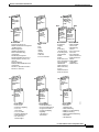
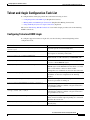
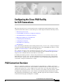
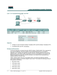
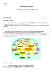
Figure 1 shows the Cisco IOS software documentation modules.
Note
Figure 1
The abbreviations (for example, FC and FR) next to the book icons are page designators,
which are defined in a key in the index of each document to help you with navigation. The
bullets under each module list the major technology areas discussed in the corresponding
books.
Cisco IOS Software Documentation Modules
IPC
FC
Cisco IOS
Configuration
Fundamentals
Configuration
Guide
Cisco IOS
Configuration
Fundamentals
Command
Reference
FR
IP2R
Module FC/FR:
• Cisco IOS User
Interfaces
• File Management
• System Management
WR
Cisco IOS
Wide-Area
Networking
Command
Reference
Module WC/WR:
• ATM
• Broadband Access
• Frame Relay
• SMDS
• X.25 and LAPB
Cisco IOS
IP Command
Reference,
Volume 1 of 3:
Addressing
and Services
Cisco IOS
IP Command
Reference,
Volume 2 of 3:
Routing
Protocols
P2C
IP3R
Cisco IOS
IP Command
Reference,
Volume 3 of 3:
Multicast
Cisco IOS
Interface
Configuration
Guide
IR
P3C
Cisco IOS
AppleTalk and
Novell IPX
Configuration
Guide
P2R
Module IPC/IP1R/IP2R/IP3R:
• IP Addressing and Services
• IP Routing Protocols
• IP Multicast
IC
Cisco IOS
Wide-Area
Networking
Configuration
Guide
IP1R
Module IC/IR:
• LAN Interfaces
• Serial Interfaces
• Logical Interfaces
P3R
Module P2C/P2R:
• AppleTalk
• Novell IPX
MWC
Cisco IOS
Interface
Command
Reference
Cisco IOS
AppleTalk and
Novell IPX
Command
Reference
Cisco IOS
Mobile
Wireless
Configuration
Guide
MWR
Cisco IOS
Mobile
Wireless
Command
Reference
Module MWC/MWR:
• General Packet
Radio Service
Cisco IOS
Apollo Domain,
Banyan VINES,
DECnet, ISO
CLNS, and XNS
Configuration
Guide
SC
Cisco IOS
Apollo Domain,
Banyan VINES,
DECnet, ISO
CLNS, and XNS
Command
Reference
Module P3C/P3R:
• Apollo Domain
• Banyan VINES
• DECnet
• ISO CLNS
• XNS
Cisco IOS
Security
Configuration
Guide
SR
Cisco IOS
Security
Command
Reference
Module SC/SR:
• AAA Security Services
• Security Server Protocols
• Traffic Filtering and Firewalls
• IP Security and Encryption
• Passwords and Privileges
• Neighbor Router Authentication
• IP Security Options
• Supported AV Pairs
47953
WC
Cisco IOS
IP
Configuration
Guide
Cisco IOS Terminal Services Configuration Guide
xvi
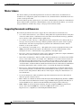
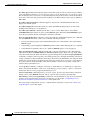
About Cisco IOS Software Documentation
Documentation Organization
Cisco IOS
Dial
Technologies
Configuration
Guide
TC
BC
Cisco IOS
Terminal
Services
Configuration
Guide
Cisco IOS
Bridging and
IBM Networking
Configuration
Guide
B2R
B1R
DR
Cisco IOS
Dial
Technologies
Command
Reference
TR
Module DC/DR:
• Preparing for Dial Access
• Modem and Dial Shelf Configuration
and Management
• ISDN Configuration
• Signalling Configuration
• Dial-on-Demand Routing
Configuration
• Dial-Backup Configuration
• Dial-Related Addressing Services
• Virtual Templates, Profiles, and
Networks
• PPP Configuration
• Callback and Bandwidth Allocation
Configuration
• Dial Access Specialized Features
• Dial Access Scenarios
VC
Cisco IOS
Voice, Video,
and Fax
Configuration
Guide
VR
Cisco IOS
Voice, Video,
and Fax
Command
Reference
Module VC/VR:
• Voice over IP
• Call Control Signalling
• Voice over
Frame Relay
• Voice over ATM
• Telephony Applications
• Trunk Management
• Fax, Video, and
Modem Support
Cisco IOS
Terminal
Services
Command
Reference
Module TC/TR:
• ARA
• LAT
• NASI
• Telnet
• TN3270
• XRemote
• X.28 PAD
• Protocol Translation
QC
Cisco IOS
Quality of
Service
Solutions
Configuration
Guide
QR
Cisco IOS
Quality of
Service
Solutions
Command
Reference
Module QC/QR:
• Packet Classification
• Congestion Management
• Congestion Avoidance
• Policing and Shaping
• Signalling
• Link Efficiency
Mechanisms
Cisco IOS
Bridging
and IBM
Networking
Command
Reference,
Volume 1 of 2
Cisco IOS
Bridging
and IBM
Networking
Command
Reference,
Volume 2 of 2
Module BC/B1R:
• Transparent
Bridging
• SRB
• Token Ring
Inter-Switch Link
• Token Ring Route
Switch Module
• RSRB
• DLSw+
• Serial Tunnel and
Block Serial Tunnel
• LLC2 and SDLC
• IBM Network
Media Translation
• SNA Frame Relay
Access
• NCIA Client/Server
• Airline Product Set
XC
Module BC/B2R:
• DSPU and SNA
Service Point
• SNA Switching
Services
• Cisco Transaction
Connection
• Cisco Mainframe
Channel Connection
• CLAW and TCP/IP
Offload
• CSNA, CMPC,
and CMPC+
• TN3270 Server
Cisco IOS
Switching
Services
Configuration
Guide
XR
Cisco IOS
Switching
Services
Command
Reference
Module XC/XR:
• Cisco IOS
Switching Paths
• NetFlow Switching
• Multiprotocol Label Switching
• Multilayer Switching
• Multicast Distributed Switching
• Virtual LANs
• LAN Emulation
47954
DC
Cisco IOS Terminal Services Configuration Guide
xvii
About Cisco IOS Software Documentation
Documentation Organization
Master Indexes
Two master indexes provide indexing information for the Cisco IOS software documentation set:
an index for the configuration guides and an index for the command references. Individual books also
contain a book-specific index.
The master indexes provide a quick way for you to find a command when you know the command name
but not which module contains the command. When you use the online master indexes, you can click
the page number for an index entry and go to that page in the online document.
Supporting Documents and Resources
The following documents and resources support the Cisco IOS software documentation set:
•
Cisco IOS Command Summary (two volumes)—This publication explains the function and syntax
of the Cisco IOS software commands. For more information about defaults and usage guidelines,
refer to the Cisco IOS command reference publications.
•
Cisco IOS System Error Messages—This publication lists and describes Cisco IOS system error
messages. Not all system error messages indicate problems with your system. Some are purely
informational, and others may help diagnose problems with communications lines, internal
hardware, or the system software.
•
Cisco IOS Debug Command Reference—This publication contains an alphabetical listing of the
debug commands and their descriptions. Documentation for each command includes a brief
description of its use, command syntax, usage guidelines, and sample output.
•
Dictionary of Internetworking Terms and Acronyms—This Cisco publication compiles and defines
the terms and acronyms used in the internetworking industry.
•
New feature documentation—The Cisco IOS software documentation set documents the mainline
release of Cisco IOS software (for example, Cisco IOS Release 12.2). New software features are
introduced in early deployment releases (for example, the Cisco IOS “T” release train for 12.2,
12.2(x)T). Documentation for these new features can be found in standalone documents called
“feature modules.” Feature module documentation describes new Cisco IOS software and hardware
networking functionality and is available on Cisco.com and the Documentation CD-ROM.
•
Release notes—This documentation describes system requirements, provides information about
new and changed features, and includes other useful information about specific software releases.
See the section “Using Software Release Notes” in the chapter “Using Cisco IOS Software” for
more information.
•
Caveats documentation—This documentation provides information about Cisco IOS software
defects in specific software releases.
•
RFCs—RFCs are standards documents maintained by the Internet Engineering Task Force (IETF).
Cisco IOS software documentation references supported RFCs when applicable. The full text of
referenced RFCs may be obtained on the World Wide Web at http://www.rfc-editor.org/.
•
MIBs—MIBs are used for network monitoring. For lists of supported MIBs by platform and
release, and to download MIB files, see the Cisco MIB website on Cisco.com at
http://www.cisco.com/public/sw-center/netmgmt/cmtk/mibs.shtml.
Cisco IOS Terminal Services Configuration Guide
xviii
About Cisco IOS Software Documentation
New and Changed Information
New and Changed Information
The Release 12.2 Cisco IOS Terminal Services Configuration Guide and Cisco IOS Terminal Services
Command Reference were extracted from Release 12.1 of the Cisco IOS Dial Services Configuration
Guide: Terminal Services and Cisco IOS Dial Services Command Reference.
Document Conventions
Within Cisco IOS software documentation, the term router is generally used to refer to a variety of Cisco
products (for example, routers, access servers, and switches). Routers, access servers, and other
networking devices that support Cisco IOS software are shown interchangeably within examples. These
products are used only for illustrative purposes; that is, an example that shows one product does not
necessarily indicate that other products are not supported.
The Cisco IOS documentation set uses the following conventions:
Convention
Description
^ or Ctrl
The ^ and Ctrl symbols represent the Control key. For example, the key combination ^D or Ctrl-D
means hold down the Control key while you press the D key. Keys are indicated in capital letters but
are not case sensitive.
string
A string is a nonquoted set of characters shown in italics. For example, when setting an SNMP
community string to public, do not use quotation marks around the string or the string will include the
quotation marks.
Command syntax descriptions use the following conventions:
Convention
Description
boldface
Boldface text indicates commands and keywords that you enter literally as shown.
italics
Italic text indicates arguments for which you supply values.
[x]
Square brackets enclose an optional element (keyword or argument).
|
A vertical line indicates a choice within an optional or required set of keywords or arguments.
[x | y]
Square brackets enclosing keywords or arguments separated by a vertical line indicate an optional
choice.
{x | y}
Braces enclosing keywords or arguments separated by a vertical line indicate a required choice.
Nested sets of square brackets or braces indicate optional or required choices within optional or
required elements. For example:
Convention
Description
[x {y | z}]
Braces and a vertical line within square brackets indicate a required choice within an optional element.
Cisco IOS Terminal Services Configuration Guide
xix
About Cisco IOS Software Documentation
Obtaining Documentation
Examples use the following conventions:
Convention
Description
screen
Examples of information displayed on the screen are set in Courier font.
boldface screen
Examples of text that you must enter are set in Courier bold font.
<
Angle brackets enclose text that is not printed to the screen, such as passwords.
>
!
[
An exclamation point at the beginning of a line indicates a comment line. (Exclamation points are also
displayed by the Cisco IOS software for certain processes.)
]
Square brackets enclose default responses to system prompts.
The following conventions are used to attract the attention of the reader:
Caution
Note
Timesaver
Means reader be careful. In this situation, you might do something that could result in
equipment damage or loss of data.
Means reader take note. Notes contain helpful suggestions or references to materials not
contained in this manual.
Means the described action saves time. You can save time by performing the action
described in the paragraph.
Obtaining Documentation
The following sections provide sources for obtaining documentation from Cisco Systems.
World Wide Web
The most current Cisco documentation is available on the World Wide Web at the following website:
http://www.cisco.com
Translated documentation is available at the following website:
http://www.cisco.com/public/countries_languages.html
Documentation CD-ROM
Cisco documentation and additional literature are available in a CD-ROM package, which ships
with your product. The Documentation CD-ROM is updated monthly and may be more current than
printed documentation. The CD-ROM package is available as a single unit or through an
annual subscription.
Cisco IOS Terminal Services Configuration Guide
xx
About Cisco IOS Software Documentation
Documentation Feedback
Ordering Documentation
Cisco documentation can be ordered in the following ways:
•
Registered Cisco Direct Customers can order Cisco product documentation from the Networking
Products MarketPlace:
http://www.cisco.com/cgi-bin/order/order_root.pl
•
Registered Cisco.com users can order the Documentation CD-ROM through the online
Subscription Store:
http://www.cisco.com/go/subscription
•
Nonregistered Cisco.com users can order documentation through a local account representative by
calling Cisco corporate headquarters (California, USA) at 408 526-7208 or, in North America, by
calling 800 553-NETS(6387).
Documentation Feedback
If you are reading Cisco product documentation on the World Wide Web, you can submit technical
comments electronically. Click Feedback in the toolbar and select Documentation. After you complete
the form, click Submit to send it to Cisco.
You can e-mail your comments to [email protected].
To submit your comments by mail, use the response card behind the front cover of your document, or
write to the following address:
Cisco Systems, Inc.
Document Resource Connection
170 West Tasman Drive
San Jose, CA 95134-9883
We appreciate your comments.
Obtaining Technical Assistance
Cisco provides Cisco.com as a starting point for all technical assistance. Customers and partners can
obtain documentation, troubleshooting tips, and sample configurations from online tools. For
Cisco.com registered users, additional troubleshooting tools are available from the TAC website.
Cisco.com
Cisco.com is the foundation of a suite of interactive, networked services that provides immediate, open
access to Cisco information and resources at anytime, from anywhere in the world. This highly
integrated Internet application is a powerful, easy-to-use tool for doing business with Cisco.
Cisco.com provides a broad range of features and services to help customers and partners streamline
business processes and improve productivity. Through Cisco.com, you can find information about Cisco
and our networking solutions, services, and programs. In addition, you can resolve technical issues with
online technical support, download and test software packages, and order Cisco learning materials and
merchandise. Valuable online skill assessment, training, and certification programs are also available.
Cisco IOS Terminal Services Configuration Guide
xxi
About Cisco IOS Software Documentation
Obtaining Technical Assistance
Customers and partners can self-register on Cisco.com to obtain additional personalized information
and services. Registered users can order products, check on the status of an order, access technical
support, and view benefits specific to their relationships with Cisco.
To access Cisco.com, go to the following website:
http://www.cisco.com
Technical Assistance Center
The Cisco TAC website is available to all customers who need technical assistance with a Cisco product
or technology that is under warranty or covered by a maintenance contract.
Contacting TAC by Using the Cisco TAC Website
If you have a priority level 3 (P3) or priority level 4 (P4) problem, contact TAC by going to the TAC
website:
http://www.cisco.com/tac
P3 and P4 level problems are defined as follows:
•
P3—Your network performance is degraded. Network functionality is noticeably impaired, but
most business operations continue.
•
P4—You need information or assistance on Cisco product capabilities, product installation, or basic
product configuration.
In each of the above cases, use the Cisco TAC website to quickly find answers to your questions.
To register for Cisco.com, go to the following website:
http://www.cisco.com/register/
If you cannot resolve your technical issue by using the TAC online resources, Cisco.com registered
users can open a case online by using the TAC Case Open tool at the following website:
http://www.cisco.com/tac/caseopen
Contacting TAC by Telephone
If you have a priority level 1 (P1) or priority level 2 (P2) problem, contact TAC by telephone and
immediately open a case. To obtain a directory of toll-free numbers for your country, go to the following
website:
http://www.cisco.com/warp/public/687/Directory/DirTAC.shtml
P1 and P2 level problems are defined as follows:
•
P1—Your production network is down, causing a critical impact to business operations if service
is not restored quickly. No workaround is available.
•
P2—Your production network is severely degraded, affecting significant aspects of your business
operations. No workaround is available.
Cisco IOS Terminal Services Configuration Guide
xxii
Using Cisco IOS Software
This chapter provides helpful tips for understanding and configuring Cisco IOS software using the
command-line interface (CLI). It contains the following sections:
•
Understanding Command Modes
•
Getting Help
•
Using the no and default Forms of Commands
•
Saving Configuration Changes
•
Filtering Output from the show and more Commands
•
Identifying Supported Platforms
For an overview of Cisco IOS software configuration, refer to the Cisco IOS Configuration
Fundamentals Configuration Guide, Release 12.2.
For information on the conventions used in the Cisco IOS software documentation set, see the chapter
“About Cisco IOS Software Documentation” located at the beginning of this book.
Understanding Command Modes
You use the CLI to access Cisco IOS software. Because the CLI is divided into many different modes,
the commands available to you at any given time depend on the mode you are currently in. Entering a
question mark (?) at the CLI prompt allows you to obtain a list of commands available for each
command mode.
When you log in to the CLI, you are in user EXEC mode. User EXEC mode contains only a limited
subset of commands. To have access to all commands, you must enter privileged EXEC mode, normally
by using a password. From privileged EXEC mode you can issue any EXEC command—user or
privileged mode—or you can enter global configuration mode. Most EXEC commands are one-time
commands. For example, show commands show important status information, and clear commands
clear counters or interfaces. The EXEC commands are not saved when the software reboots.
Configuration modes allow you to make changes to the running configuration. If you later save the
running configuration to the startup configuration, these changed commands are stored when the
software is rebooted. To enter specific configuration modes, you must start at global configuration
mode. From global configuration mode, you can enter interface configuration mode and a variety of
other modes, such as protocol-specific modes.
ROM monitor mode is a separate mode used when the Cisco IOS software cannot load properly. If a
valid software image is not found when the software boots or if the configuration file is corrupted at
startup, the software might enter ROM monitor mode.
Cisco IOS Terminal Services Configuration Guide
xxiii
Using Cisco IOS Software
Getting Help
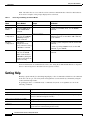
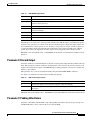
Table 1 describes how to access and exit various common command modes of the Cisco IOS software.
It also shows examples of the prompts displayed for each mode.
Table 1
Accessing and Exiting Command Modes
Command
Mode
Access Method
Prompt
Exit Method
User EXEC
Log in.
Router>
Use the logout command.
Privileged
EXEC
From user EXEC mode,
use the enable EXEC
command.
Router#
To return to user EXEC mode, use the disable
command.
Global
configuration
From privileged EXEC
mode, use the configure
terminal privileged
EXEC command.
Router(config)#
To return to privileged EXEC mode from global
configuration mode, use the exit or end command,
or press Ctrl-Z.
Interface
configuration
From global
configuration mode,
specify an interface using
an interface command.
Router(config-if)#
To return to global configuration mode, use the exit
command.
From privileged EXEC
mode, use the reload
EXEC command. Press
the Break key during the
first 60 seconds while the
system is booting.
>
ROM monitor
To return to privileged EXEC mode, use the end
command, or press Ctrl-Z.
To exit ROM monitor mode, use the continue
command.
For more information on command modes, refer to the “Using the Command-Line Interface” chapter in
the Cisco IOS Configuration Fundamentals Configuration Guide.
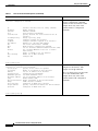
Getting Help
Entering a question mark (?) at the CLI prompt displays a list of commands available for each command
mode. You can also get a list of keywords and arguments associated with any command by using the
context-sensitive help feature.
To get help specific to a command mode, a command, a keyword, or an argument, use one of the
following commands:
Command
Purpose
help
Provides a brief description of the help system in any command mode.
abbreviated-command-entry?
Provides a list of commands that begin with a particular character string. (No space
between command and question mark.)
abbreviated-command-entry<Tab>
Completes a partial command name.
?
Lists all commands available for a particular command mode.
command ?
Lists the keywords or arguments that you must enter next on the command line.
(Space between command and question mark.)
Cisco IOS Terminal Services Configuration Guide
xxiv
Using Cisco IOS Software
Getting Help
Example: How to Find Command Options
This section provides an example of how to display syntax for a command. The syntax can consist of
optional or required keywords and arguments. To display keywords and arguments for a command, enter
a question mark (?) at the configuration prompt or after entering part of a command followed by a space.
The Cisco IOS software displays a list and brief description of available keywords and arguments. For
example, if you were in global configuration mode and wanted to see all the keywords or arguments for
the arap command, you would type arap ?.
The <cr> symbol in command help output stands for “carriage return.” On older keyboards, the carriage
return key is the Return key. On most modern keyboards, the carriage return key is the Enter key. The
<cr> symbol at the end of command help output indicates that you have the option to press Enter to
complete the command and that the arguments and keywords in the list preceding the <cr> symbol are
optional. The <cr> symbol by itself indicates that no more arguments or keywords are available and that
you must press Enter to complete the command.
Table 2 shows examples of how you can use the question mark (?) to assist you in entering commands.
The table steps you through configuring an IP address on a serial interface on a Cisco 7206 router that
is running Cisco IOS Release 12.0(3).
Table 2
How to Find Command Options
Command
Comment
Router> enable
Password: <password>
Router#
Enter the enable command and
password to access privileged EXEC
commands. You are in privileged
EXEC mode when the prompt changes
to Router#.
Router# configure terminal
Enter configuration commands, one per line. End with CNTL/Z.
Router(config)#
Enter the configure terminal
privileged EXEC command to enter
global configuration mode. You are in
global configuration mode when the
prompt changes to Router(config)#.
Router(config)# interface serial ?
<0-6>
Serial interface number
Router(config)# interface serial 4 ?
/
Router(config)# interface serial 4/ ?
<0-3>
Serial interface number
Router(config)# interface serial 4/0
Router(config-if)#
Enter interface configuration mode by
specifying the serial interface that you
want to configure using the interface
serial global configuration command.
Enter ? to display what you must enter
next on the command line. In this
example, you must enter the serial
interface slot number and port number,
separated by a forward slash.
You are in interface configuration mode
when the prompt changes to
Router(config-if)#.
Cisco IOS Terminal Services Configuration Guide
xxv
Using Cisco IOS Software
Getting Help
Table 2
How to Find Command Options (continued)
Command
Comment
Router(config-if)# ?
Interface configuration commands:
.
.
.
ip
Interface Internet Protocol config commands
keepalive
Enable keepalive
lan-name
LAN Name command
llc2
LLC2 Interface Subcommands
load-interval
Specify interval for load calculation for an
interface
locaddr-priority
Assign a priority group
logging
Configure logging for interface
loopback
Configure internal loopback on an interface
mac-address
Manually set interface MAC address
mls
mls router sub/interface commands
mpoa
MPOA interface configuration commands
mtu
Set the interface Maximum Transmission Unit (MTU)
netbios
Use a defined NETBIOS access list or enable
name-caching
no
Negate a command or set its defaults
nrzi-encoding
Enable use of NRZI encoding
ntp
Configure NTP
.
.
.
Router(config-if)#
Enter ? to display a list of all the
interface configuration commands
available for the serial interface. This
example shows only some of the
available interface configuration
commands.
Router(config-if)# ip ?
Interface IP configuration subcommands:
access-group
Specify access control for packets
accounting
Enable IP accounting on this interface
address
Set the IP address of an interface
authentication
authentication subcommands
bandwidth-percent
Set EIGRP bandwidth limit
broadcast-address
Set the broadcast address of an interface
cgmp
Enable/disable CGMP
directed-broadcast Enable forwarding of directed broadcasts
dvmrp
DVMRP interface commands
hello-interval
Configures IP-EIGRP hello interval
helper-address
Specify a destination address for UDP broadcasts
hold-time
Configures IP-EIGRP hold time
.
.
.
Router(config-if)# ip
Enter the command that you want to
configure for the interface. This
example uses the ip command.
Cisco IOS Terminal Services Configuration Guide
xxvi
Enter ? to display what you must enter
next on the command line. This
example shows only some of the
available interface IP configuration
commands.
Using Cisco IOS Software
Using the no and default Forms of Commands
Table 2
How to Find Command Options (continued)
Command
Comment
Router(config-if)# ip address ?
A.B.C.D
IP address
negotiated
IP Address negotiated over PPP
Router(config-if)# ip address
Enter the command that you want to
configure for the interface. This
example uses the ip address command.
Enter ? to display what you must enter
next on the command line. In this
example, you must enter an IP address
or the negotiated keyword.
A carriage return (<cr>) is not
displayed; therefore, you must enter
additional keywords or arguments to
complete the command.
Enter the keyword or argument you
want to use. This example uses the
172.16.0.1 IP address.
Router(config-if)# ip address 172.16.0.1 ?
A.B.C.D
IP subnet mask
Router(config-if)# ip address 172.16.0.1
Enter ? to display what you must enter
next on the command line. In this
example, you must enter an IP subnet
mask.
A <cr> is not displayed; therefore, you
must enter additional keywords or
arguments to complete the command.
Router(config-if)# ip address 172.16.0.1 255.255.255.0 ?
secondary
Make this IP address a secondary address
<cr>
Router(config-if)# ip address 172.16.0.1 255.255.255.0
Enter the IP subnet mask. This example
uses the 255.255.255.0 IP subnet mask.
Enter ? to display what you must enter
next on the command line. In this
example, you can enter the secondary
keyword, or you can press Enter.
A <cr> is displayed; you can press
Enter to complete the command, or
you can enter another keyword.
Router(config-if)# ip address 172.16.0.1 255.255.255.0
Router(config-if)#
In this example, Enter is pressed to
complete the command.
Using the no and default Forms of Commands
Almost every configuration command has a no form. In general, use the no form to disable a function.
Use the command without the no keyword to reenable a disabled function or to enable a function that
is disabled by default. For example, IP routing is enabled by default. To disable IP routing, use the no
ip routing command; to reenable IP routing, use the ip routing command. The Cisco IOS software
command reference publications provide the complete syntax for the configuration commands and
describe what the no form of a command does.
Configuration commands also can have a default form, which returns the command settings to the
default values. Most commands are disabled by default, so in such cases using the default form has the
same result as using the no form of the command. However, some commands are enabled by default and
Cisco IOS Terminal Services Configuration Guide
xxvii
Using Cisco IOS Software
Saving Configuration Changes
have variables set to certain default values. In these cases, the default form of the command enables the
command and sets the variables to their default values. The Cisco IOS software command reference
publications describe the effect of the default form of a command if the command functions differently
than the no form.
Saving Configuration Changes
Use the copy system:running-config nvram:startup-config command to save your configuration
changes to the startup configuration so that the changes will not be lost if the software reloads or a
power outage occurs. For example:
Router# copy system:running-config nvram:startup-config
Building configuration...
It might take a minute or two to save the configuration. After the configuration has been saved, the
following output appears:
[OK]
Router#
On most platforms, this task saves the configuration to NVRAM. On the Class A Flash file system
platforms, this task saves the configuration to the location specified by the CONFIG_FILE environment
variable. The CONFIG_FILE variable defaults to NVRAM.
Filtering Output from the show and more Commands
In Cisco IOS Release 12.0(1)T and later releases, you can search and filter the output of show and more
commands. This functionality is useful if you need to sort through large amounts of output or if you
want to exclude output that you need not see.
To use this functionality, enter a show or more command followed by the “pipe” character (|); one of
the keywords begin, include, or exclude; and a regular expression on which you want to search or filter
(the expression is case-sensitive):
command | {begin | include | exclude} regular-expression
The output matches certain lines of information in the configuration file. The following example
illustrates how to use output modifiers with the show interface command when you want the output to
include only lines in which the expression “protocol” appears:
Router# show interface | include protocol
FastEthernet0/0 is up, line protocol is up
Serial4/0 is up, line protocol is up
Serial4/1 is up, line protocol is up
Serial4/2 is administratively down, line protocol is down
Serial4/3 is administratively down, line protocol is down
For more information on the search and filter functionality, refer to the “Using the Command-Line
Interface” chapter in the Cisco IOS Configuration Fundamentals Configuration Guide, Release 12.2.
Cisco IOS Terminal Services Configuration Guide
xxviii
Using Cisco IOS Software
Identifying Supported Platforms
Identifying Supported Platforms
Cisco IOS software is packaged in feature sets consisting of software images that support specific
platforms. The feature sets available for a specific platform depend on which Cisco IOS software
images are included in a release. To identify the set of software images available in a specific release
or to find out if a feature is available in a given Cisco IOS software image, see the following sections:
•
Using Feature Navigator
•
Using Software Release Notes
Using Feature Navigator
Feature Navigator is a web-based tool that enables you to quickly determine which Cisco IOS software
images support a particular set of features and which features are supported in a particular Cisco IOS
image.
Feature Navigator is available 24 hours a day, 7 days a week. To access Feature Navigator, you must
have an account on Cisco.com. If you have forgotten or lost your account information, e-mail the
Contact Database Administration group at [email protected]. If you do not have an account on
Cisco.com, go to http://www.cisco.com/register and follow the directions to establish an account.
To use Feature Navigator, you must have a JavaScript-enabled web browser such as Netscape 3.0 or
later, or Internet Explorer 4.0 or later. Internet Explorer 4.0 always has JavaScript enabled. To enable
JavaScript for Netscape 3.x or Netscape 4.x, follow the instructions provided with the web browser. For
JavaScript support and enabling instructions for other browsers, check with the browser vendor.
Feature Navigator is updated when major Cisco IOS software releases and technology releases occur.
You can access Feature Navigator at the following URL:
http://www.cisco.com/go/fn
Using Software Release Notes
Cisco IOS software releases include release notes that provide the following information:
•
Platform support information
•
Memory recommendations
•
Microcode support information
•
Feature set tables
•
Feature descriptions
•
Open and resolved severity 1 and 2 caveats for all platforms
Release notes are intended to be release-specific for the most current release, and the information
provided in these documents may not be cumulative in providing information about features that first
appeared in previous releases.
Cisco IOS Terminal Services Configuration Guide
xxix
Using Cisco IOS Software
Identifying Supported Platforms
Cisco IOS Terminal Services Configuration Guide
xxx
Terminal Services Overview
This chapter provides an overview of Cisco IOS terminal services and includes the following main
sections:
•
Cisco IOS Network Access Devices
•
Line Characteristics and Modems
•
Asynchronous Character Stream Calls
•
Remote Node Services
•
Terminal Services
•
Protocol Translation
Cisco IOS Network Access Devices
Network devices that support access services enable single users to access network resources from
remote sites. Remote users include corporate telecommuters, mobile users, and individuals in remote
offices who access the central site. Access services connect remote users over serial lines to modems,
networks, terminals, printers, workstations, and other network resources on LANs and WANs. In
contrast, routers that do not support access services connect LANs or WANs.
Note
Access services are supported on the Cisco 2500, Cisco 2600, and Cisco 3600 series routers. See the
Cisco Products Quick Reference Guide, available at Cisco.com, for more information about Cisco devices
for terminal and modem access services.
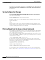
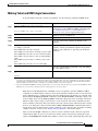
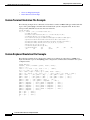
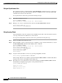
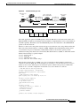
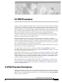
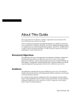
Figure 2 illustrates the following access services available in the Cisco IOS software:
•
Terminal services are shown between the terminals and hosts running the same protocol (LAT to
LAT or TCP to TCP).
•
Protocol translation is supported between the terminals and hosts running unlike protocols (such as
LAT to TCP or TCP to LAT).
Asynchronous IP routing is shown by the PC running Serial Line Internet Protocol (SLIP) or
Point-to-Point Protocol (PPP), and between the two access servers. Asynchronous routing configuration
is described in the Cisco IOS Terminal Services Configuration Guide, Release 12.2.
Cisco IOS Terminal Services Configuration Guide
TC-1
Terminal Services Overview
Line Characteristics and Modems
Figure 2
Access Service Functions
Branch Office
Mobile user
with PowerBook
PC (TCP)
PC (LAT)
Modem
Modem
Modem
Access
server
Modem
Telecommuter PC
(using PPP callback)
Terminal (LAT)
Terminal (TCP)
IP
Access
server
NCD terminal
Modem
ASCII terminal
X.25 WAN
UNIX host (TCP)
VMS host (LAT)
Central Office
S4201
PAD
Line Characteristics and Modems
The Cisco IOS software permits you to connect to asynchronous serial devices such as terminals and
modems and to configure custom device operation. You can configure a single physical or virtual line
or a range of lines. For example, you can configure one line for a laser printer and then configure a set
of lines to switch incoming modem connections to the next available line. You also can customize your
configurations. For example, you can define line-specific transport protocols, control character, and
packet transmissions, set line speed, flow control, and establish time limits for user access.
The chapters in this publication describe how to configure the lines for a specific device application. See
the chapter “Configuring Protocol Translation and Virtual Asynchronous Devices” in this publication,
and the chapters “Interfaces, Controllers, and Lines Used for Dial Access Overview” and “Preparing
Modem and Asynchronous Interfaces” in the Cisco IOS Dial Technologies Configuration Guide for
additional information about configuring Cisco asynchronous serial interfaces.
Cisco IOS Terminal Services Configuration Guide
TC-2
Terminal Services Overview
Asynchronous Character Stream Calls
Asynchronous Character Stream Calls
Asynchronous character stream calls enter the router or access server through virtual terminal (vty) lines
and virtual asynchronous interfaces (vty-async). These virtual lines and interfaces terminate incoming
character streams that have no physical connection to the access server or router (such as a physical
serial interface). For example, if you begin a PPP session over an asynchronous character stream, a
vty-async interface is created to support the call. The following types of calls are terminated on a virtual
asynchronous interface: Telnet, local-area transport (LAT), V.120, TN3270, and Link Access
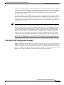
Procedure, Balanced-terminal adapter (LAPB-TA) and packet assembler/disassembler (PAD) calls.
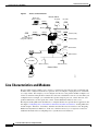
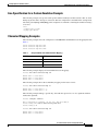
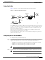
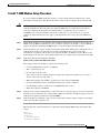
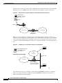
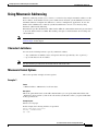
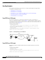
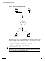
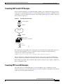
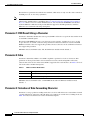
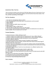
Figure 3 shows a dumb terminal using a modem and packet assembler/disassembler (PAD) to place a call
in to an X.25 switched network. The Cisco 4700-M router is configured to support vty lines and
vty-async interfaces.
Figure 3
Standard X.25 Dial-Up Connection
Dumb terminal
making a connection
with an X.25 host
Modem
PAD
Modem
X.25
X.25
X.25
Cisco 4700-M
with internal
PAD application
X.25 network
S6700
X.25 network
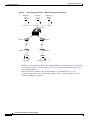
Remote Node Services
Remote node services permit remote users to connect devices over a telephone network using the
following protocols:
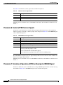
•
AppleTalk Remote Access (ARA), which is described in the chapter “Configuring AppleTalk
Remote Access” in this publication.
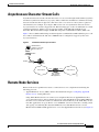
Using ARA, Macintosh users can connect across telephone lines into an AppleTalk network to
access network resources, such as printers, file servers, and e-mail. Remote users running ARA have
the same access to network resources as a Macintosh connected directly to the LAN. They can also
run other applications on top of ARA to access UNIX file servers for such tasks as reading e-mail
and copying or transferring files between UNIX hosts. Note that Macintosh users can run
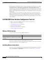
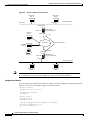
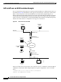
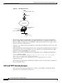
Macintosh-based SLIP or PPP applications to access non-AppleTalk-based resources (see Figure 4).
Cisco IOS Terminal Services Configuration Guide
TC-3
Terminal Services Overview
Remote Node Services
Figure 4
Remote Node Connection—Macintosh and PC Users Dialing In
AppleShare
server
UNIX mail
server
AppleShare
Server
Modem
Modem
Modem
Modem
Macintosh
•
PC (Windows 95)
S2247
Access server
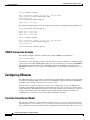
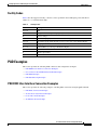
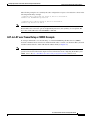
XRemote, the Network Control Device, Inc. (NCD) X Window Systems terminal protocol, which is
described in the section “Configuring XRemote” in the “Configuring Dial-In Terminal Services”
chapter in this publication.
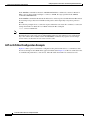
Remote users with X terminals, such as NCD terminals, use the XRemote protocol over
asynchronous lines. The router provides network functionality to remote X terminals. Figure 5
illustrates an XRemote connection.
Cisco IOS Terminal Services Configuration Guide
TC-4
Terminal Services Overview
Remote Node Services
Figure 5
XRemote Connection
NCD X terminal
running XRemote
S1923
Access server
UNIX host
(TCP/IP)
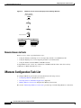
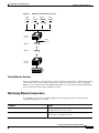
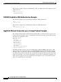
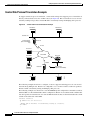
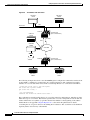
NetWare Access Server Interface (NASI) server, which is described in the chapter “Configuring
Support for NASI Clients to Access Network Resources” in this publication. Configuring a NASI
server enables NASI clients to connect to asynchronous resources attached to a router. NASI clients
are connected to the Ethernet interface 0 on the router. When the user on the NASI client uses the
Windows or DOS application to connect to the router, a list of available terminal and virtual terminal
lines appears. The user selects the desired outgoing terminal and virtual terminal port. (See
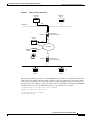
Figure 6.)
Figure 6
NASI Setup in a NetWare Environment
Modem
NASI
client
NetWare
connect
server
Modem
ASCII printer
S3914
•
DEC VMS
host (LAT)
Cisco IOS Terminal Services Configuration Guide
TC-5
Terminal Services Overview
Terminal Services
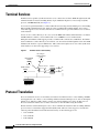
Terminal Services
Terminal services permit asynchronous devices to be connected to a LAN or WAN through network and
terminal-emulation software including Telnet, rlogin, NASI, the Digital local-area transport (LAT)
protocol, and IBM TN3270. (See Figure 7.)
Access services permit terminals to connect with remote hosts using virtual terminal protocols including
Telnet, NASI, LAT, TN3270, rlogin, and X.25 packet assembler/disassembler (PAD). You can use a
router that supports access services to function as a terminal server to provide terminal access to devices
on the network.
A host can also connect directly to an access server. In IBM environments, TN3270 allows a standard
ASCII terminal to emulate a 3278 terminal and access an IBM host across an IP network.
In Digital environments, LAT support provides a terminal with connections to VMS hosts. X.25 PAD
allows terminals to connect directly to an X.25 host over an X.25 network through the router. X.25 PAD
eliminates the need for a separate PAD device. This connection requires use of one of the synchronous
serial interfaces on the router supporting access services.
Figure 7
Terminal-to-Host Connectivity
PC acting as
a dumb terminal
Desktop NCD
terminal
Access server
Modem
Modem
S2223
Dumb terminal
UNIX host
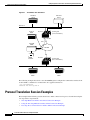
Protocol Translation
Protocol translation services are essentially an extension of terminal services. A user running a TCP/IPbased application can connect to a host running a different virtual terminal protocol, such as the Digital
LAT protocol. The Cisco IOS software converts one virtual terminal protocol into another protocol.
Protocol translation enables users to make connections to X.25 machines using X.25 PAD.
Routers translate virtual terminal protocols to allow communication between devices running different
protocols. Protocol translation supports Telnet (TCP), LAT, and X.25. One-step protocol translation
software performs bidirectional translation between any of the following protocols:
•
X.25 and TCP
•
X.25 and LAT
•
LAT and TCP
Cisco IOS Terminal Services Configuration Guide
TC-6
Terminal Services Overview
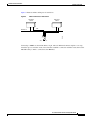
Protocol Translation
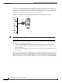
Figure 8 illustrates LAT-to-TCP protocol translation.
Figure 8
LAT-to-TCP Protocol Translation
LAT device
LAT-A
Network A
TCP device
TCP-A
LAT
S1033b
Telnet
Access server
Connecting to IBM hosts from LAT, Telnet, rlogin, and X.25 PAD environments requires a two-step
translation process. In other words, users must first establish a connection with the router, then use the
TN3270 facility to make a connection to the IBM host.
Cisco IOS Terminal Services Configuration Guide
TC-7
Terminal Services Overview
Protocol Translation
Cisco IOS Terminal Services Configuration Guide
TC-8
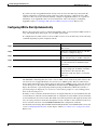
Configuring Terminal Operating Characteristics
for Dial-In Sessions
This chapter describes how to set operating characteristics for remote terminal service connections. It
includes the following main sections:
•
Terminal Operating Characteristics Overview
•
Selecting a Preferred Connection Protocol
•
Configuring Communication Parameters for Terminal Ports
For a complete description of the terminal characteristic commands in this chapter, refer to the Cisco
IOS Terminal Services Command Reference, Release 12.2. To locate documentation of other commands
that appear in this chapter, use the command reference master index or search online.
To identify the hardware platform or software image information associated with a feature, use the
Feature Navigator on Cisco.com to search for information about the feature or refer to the software
release notes for a specific release. For more information, see the “Identifying Supported Platforms”
section in the “Using Cisco IOS Software” chapter.
Terminal Operating Characteristics Overview
In line configuration mode, you can set terminal operating characteristics that will be in operation for
that line until the next time you change the line parameters. Alternatively, you can change the line setting
locally (temporarily) with terminal EXEC commands. Both tasks are described in this chapter.
Selecting a Preferred Connection Protocol
Your first task is to select a preferred connection protocol, then configure the appropriate communication
parameters. The preferred transport type is your preferred connection protocol. To configure the router
to support specific protocols, perform the tasks described in the following sections:
•
Specifying the Transport Protocol
•
Specifying a Local Transport Protocol
Cisco IOS Terminal Services Configuration Guide
TC-9
Configuring Terminal Operating Characteristics for Dial-In Sessions
Selecting a Preferred Connection Protocol
Specifying the Transport Protocol
Use the transport preferred command to specify which transport protocol is used on connections. Use
the transport input and transport output commands to explicitly specify the protocols allowed on
individual lines for both incoming and outgoing connections.
Note
Cisco routers do not accept incoming network connections to asynchronous ports (TTY lines) by
default. You must specify an incoming transport protocol, or specify the transport input all
command before the line will accept incoming connections. For example, if you are using your router
as a terminal server to make console-port connections to routers or other devices, you will not be able
to use Telnet to connect to these devices. You will receive the message “Connection Refused.”
For routers that support the Digital local-area transport (LAT) protocol, the default protocol for outgoing
connections is LAT. For those that do not support LAT, the default protocol for outgoing connections is
Telnet. For incoming connections, all the supported network protocols are accepted (the default protocol
is the all keyword).
To specify transport protocols, use one or more of the following commands in line configuration mode:
Command
Purpose
Router(config-line)# transport input {all | lat | mop
| nasi | none | pad | rlogin | ssh | telnet | v120}
Defines which protocols can be used to connect to a specific
line.
Router(config-line)# transport output {all | lat | mop
| nasi | none | pad | rlogin | telnet | v120}
Determines the protocols that can be used for outgoing
connections from a line.
Router(config-line)# transport preferred {all | lat |
mop | nasi | pad | rlogin | telnet | v120}
Specifies the protocol for the router to use if the user did not
specify a protocol.
Router(config-line)# transport preferred none
Prevents errant connection attempts.
The IOS software accepts a host name entry at the EXEC system prompt as a Telnet command. If you
enter the host name incorrectly, the router interprets the entry as an incorrect Telnet command and
provides an error message indicating that the host does not exist. The transport preferred none
command disables this option so that if you enter a command incorrectly at the EXEC prompt, the
software does not attempt to make a Telnet connection to a host that it cannot find.
The transport preferred command setting specifies a search order when attempting to resolve names
that might be valid for multiple protocols. If the address or service does not match the preferred protocol,
all other valid output protocols are searched to find a valid match.
Specifying a Local Transport Protocol
You can configure the Cisco IOS software to save local parameters between sessions. These local
parameters are set with terminal EXEC commands.
Cisco IOS Terminal Services Configuration Guide
TC-10
Configuring Terminal Operating Characteristics for Dial-In Sessions
Configuring Communication Parameters for Terminal Ports
To specify the preferred protocol to use for the current session when a command does not specify one,
use the following command in EXEC mode:
Command
Purpose
Router> terminal transport preferred {all | lat | mop
| nasi | none | pad | rlogin | telnet | v120}
Specifies the protocol for the Cisco IOS software to use for
the current session if the user did not specify a protocol.
The preferred transport type is your preferred connection protocol. This setting specifies a protocol
search order that the Cisco IOS software uses when it attempts to resolve a device name that you enter,
but you do not specify a connection protocol. For example, if you want to connect to a TCP/IP host
named host1 and want to use Telnet, you enter the telnet host1 command. However, if your preferred
connection protocol is set to Telnet, you could enter only the host1 argument and be connected to the
device. A host name might be valid for multiple protocols. If the address or service does not match the
preferred protocol, all other valid connection protocols are searched to find a valid match for the name.
For router software images that support LAT, the default protocol for outgoing connections is LAT. For
router software images that do not support LAT, the default protocol for outgoing connections is Telnet.
For incoming connections, all the supported network protocols are accepted (the default protocol is the
all keyword).
The Cisco IOS software accepts a host name entry at the EXEC prompt as a Telnet command. If you
enter the host name incorrectly, the Cisco IOS software interprets the entry as an incorrect Telnet
command and provides an error message indicating that the host does not exist. The transport preferred
none command disables this option so that if you enter a command incorrectly at the EXEC prompt, the
Cisco IOS software does not attempt to make a Telnet connection.
Configuring Communication Parameters for Terminal Ports
To configure communication parameters, perform the tasks described in the following sections:
•
Configuring Sessions on a Line (Required)
•
Configuring Local Session Parameters (As Required)
•
Changing the Default Privilege Level for Lines (As Required)
•
Enabling Password Checking at Login (As Required)
•
Establishing Terminal Session Limits (As Required)
•
Displaying Line Connection Information After the Login Prompt (As Required)
Configuring Sessions on a Line
The Cisco IOS software supplies the following default serial communication parameters for terminal and
other serial device operation:
•
9600 bits per second (bps) line speed
•
8 data bits
•
2 stop bits
•
No parity bit
Cisco IOS Terminal Services Configuration Guide
TC-11
Configuring Terminal Operating Characteristics for Dial-In Sessions
Configuring Communication Parameters for Terminal Ports
To change the default parameters as necessary to meet the requirements of the terminal or host to which
you are connected, use any of the following commands in line configuration mode:
Command
Purpose
Router(config-line)# speed bps
Sets the line speed. Choose from line speed,
transmit speed, or receive speed.
or
Router(config-line)# txspeed bps
or
Router(config-line)# rxspeed bps
Router(config-line)# databits {5 | 6 | 7 | 8}
Sets the data bits.
Router(config-line)# stopbits {1 | 1.5 | 2}
Sets the stop bits.
Router(config-line)# parity {none | even | odd | space | mark}
Sets the parity bit.
Configuring Local Session Parameters
To change these parameters as necessary to meet the requirements of the terminal or host to which you
are attached, use the following commands in EXEC mode, as needed:
Command
Purpose
Router> terminal speed bps
Sets the line speed for the current session.
Choose from line speed, transmit speed, or
receive speed.
or
Router> terminal txspeed bps
or
Router> terminal rxspeed bps
Router> terminal databits {5 | 6 | 7 | 8}
Sets the data bits for the current session.
Router> terminal stopbits {1 | 1.5 | 2}
Sets the stop bits for the current session.
Router> terminal parity {none | even | odd | space | mark}
Sets the parity bit for the current session.
Changing the Default Privilege Level for Lines
To change the default privilege level for a given line or a group of lines, use the following command in
line configuration mode:
Command
Purpose
Router(config-line)# privilege level level
Specifies a default privilege level for a line.
Cisco IOS Terminal Services Configuration Guide
TC-12
Configuring Terminal Operating Characteristics for Dial-In Sessions
Configuring Communication Parameters for Terminal Ports
Enabling Password Checking at Login
You can enable password checking on a particular line so that the user is prompted to enter a password
at the system login screen. You must then also specify a password. To do so, use the following commands
in line configuration mode:
Command
Purpose
Step 1 Router(config-line)# login
Enables password checking on a per-line basis using the password
specified with the password command.
Step 2 Router(config-line)# password password
Assigns a password to a particular line.
You can enable password checking on a per-user basis, in which case authentication is based on the
username specified with the username global configuration command. To enable password checking on
a per-user basis, use the following commands in line configuration mode:
Command
Purpose
Step 1 Router(config-line)# login local
Enables password checking on a per-user basis using the username
and password specified with the username global configuration
command.
Step 2 Router(config-line)# login tacacs
Selects the TACACS style user ID and password-checking
mechanism.
or
Router(config-line)# login authentication
{default | list-name}
Use the login tacacs command with TACACS and extended TACACS. Use the login authentication
command with AAA/TACACS+.
By default, virtual terminals require passwords. If you do not set a password for a virtual terminal, the
router displays an error message and closes the attempted connection. Use the no login command to
disable this function and allow connections without a password.
For other access control tasks and password restrictions, including the enable password global
configuration command that restricts access to privileged mode, see the Cisco IOS Security
Configuration Guide, Release 12.2.
Establishing Terminal Session Limits
You might need to control terminal sessions in high-traffic areas to provide resources for all users. You
can define the following limitations for terminal sessions:
•
The maximum number of sessions
•
The idle session timeout interval or the absolute timeout interval
Cisco IOS Terminal Services Configuration Guide
TC-13
Configuring Terminal Operating Characteristics for Dial-In Sessions
Configuring Communication Parameters for Terminal Ports
To establish terminal session limits, use the following commands in line configuration mode:
Command
Purpose
Step 1
Router(config-line)# session-limit session-number
Sets the maximum number of simultaneous
sessions.1
Step 2
Router(config-line)# session-timeout minutes [output]
Sets the idle session timeout interval.
or
Router(config-line)# absolute-timeout minutes
Sets the absolute timeout interval.
Step 3
Router(config-line)# logout-warning [seconds]
1.
Warns users of impending timeouts set with the
absolute-timeout command.
There is no inherent upper limit to the number of sessions you can create.
Note
The absolute-timeout command overrides any timeouts set through the AppleTalk Remote Access
(ARA) protocol.
Displaying Line Connection Information After the Login Prompt
You can display the host name, line number, and location of the host each time an EXEC session is
started or an incoming connection is made. The line number banner appears immediately after the EXEC
banner or incoming banner. This feature is useful for tracking problems with modems because it lists the
host and line for the modem connection. Modem type information is also included if applicable.
To provide line information after the login prompt, use the following command in global configuration
mode:
Command
Purpose
Router(config)# service linenumber
Provides service line number information after the
EXEC banner or incoming banner.
Cisco IOS Terminal Services Configuration Guide
TC-14
Configuring Dial-In Terminal Services
This chapter describes how to configure support for asynchronous character stream calls running Telnet,
rlogin, local-area transport (LAT), XRemote, or TN3270. It includes the following main sections:
•
Dial-In Terminal Service Overview
•
Configuring Telnet and rlogin
•
Telnet and rlogin Configuration Task List
•
Using Cisco DialOut for Telnet Connections
•
Configuring LAT
•
LAT Configuration Task List
•
Monitoring and Maintaining LAT Connections
•
LAT Configuration and Connection Examples
•
Configuring TN3270
•
TN3270 Configuration Task List
•
TN3270 Configuration and Connection Examples
•
Configuring XRemote
•
XRemote Configuration Task List
•
XRemote Configuration and Connection Examples
For a complete description of the dial-in terminal services commands in this chapter, refer to the Cisco
IOS Terminal Services Command Reference, Release 12.2. To locate documentation of other commands
that appear in this chapter, use the command reference master index or search online.
Dial-In Terminal Service Overview
Inbound asynchronous character stream calls are routed to virtual terminal lines and virtual
asynchronous interfaces, which are used to terminate incoming character steams that do not share a
physical connection with the access server or router (such as a physical interface). A virtual
asynchronous interface is the place where inbound Telnet, LAT, V.120, TN3270, and packet
assembler/disassembler (PAD) calls or sessions terminate on the router. Virtual terminal lines are used
for attaching to the router in a nonphysical way.
Configuring support for terminal service connections means enabling network devices running the same
protocol to connect across a LAN or WAN through network and terminal-emulation software.
Cisco IOS Terminal Services Configuration Guide
TC-15
Configuring Dial-In Terminal Services
Configuring Telnet and rlogin
The following sections describe how to configure these supported dial-in terminal services:
•
Configuring Telnet and rlogin—Of all protocol suites, TCP/IP is the most widely implemented on
networks of all media types. TCP/IP is the current standard for internetworking and is supported by
most computer vendors, including all UNIX-based workstation manufacturers. TCP/IP includes
Telnet and rlogin.
•
Configuring LAT—The proprietary LAT terminal connection protocol from Digital Equipment
Corporation used with Digital minicomputers.
•
Configuring TN3270—IBM 3278 terminal emulation provides TN3270-based connectivity to IBM
hosts over serial lines.
•
Configuring XRemote—The X Window Systems terminal protocol from Network Control Devices,
Inc., provides network functionality to remote X terminals.
Each section provides examples of how to configure and connect to a terminal service.
Configuring Telnet and rlogin
Telnet and rlogin are protocols that enable TCP/IP connections to a host. Telnet, a virtual terminal
protocol that is part of the TCP/IP protocol suite, is the more widely used protocol. The rlogin protocol
is a remote login service developed for the Berkeley Software Distribution (BSD) UNIX system. It
provides better control and output suppression than Telnet, but can only be used when the host (typically,
a UNIX system) supports rlogin. The Cisco IOS implementation of rlogin does not subscribe to the
rlogin “trusted host” model. That is, a user cannot automatically log in to a UNIX system from the router,
but must provide a user ID and a password for each connection.
Telnet allows a user at one site to establish a TCP connection to a login server at another site, then passes
the keystrokes from one system to the other. Telnet can accept either an IP address or a domain name as
the remote system address. In short, Telnet offers three main services:
•
Network virtual terminal connection
•
Option negotiation
•
Symmetric connection
The Cisco implementation of Telnet supports the following Telnet options:
•
Remote echo
•
Binary transmission
•
Suppress go ahead
•
Timing mark
•
Terminal type
•
Send location
•
Terminal speed
•
Remote flow control
•
X display location
Cisco IOS Terminal Services Configuration Guide
TC-16
Configuring Dial-In Terminal Services
Telnet and rlogin Configuration Task List
Telnet and rlogin Configuration Task List
To configure Telnet and rlogin, perform the tasks in the following sections:
•
Configuring Telnet and UNIX rlogin (Required for Service)
•
Making Telnet and UNIX rlogin Connections (Required for Making Connections)
•
Using UNIX Style Syntax for rlogin Connections (Optional)
The section “Monitoring TCP/IP Connections” later in this chapter provides tasks for maintaining
TCP/IP connections.
Configuring Telnet and UNIX rlogin
To configure support for Telnet or rlogin calls, use the following commands beginning in line
configuration mode.
Command
Purpose
Router(config-line)# telnet speed default-speed
maximum-speed
Negotiates speeds on reverse Telnet lines.
Router(config-line)# telnet refuse-negotiations
Causes Telnet to refuse to negotiate full-duplex, remote
echo requests on incoming connections.
Router(config-line)# telnet transparent
Sets line to send a RETURN (CR) as a CR followed by a
NULL instead of a CR followed by a LINE FEED (LF).
Router(config-line)# telnet sync-on-break
Sets the line to send a Telnet SYNCHRONIZE signal when
it receives a Telnet BREAK signal.
Router(config-line)# telnet break-on-ip
Sets the line to cause the system to generate a hardware
BREAK signal on the EIA/TIA-232 line that is associated
with a reverse Telnet connection when a Telnet
Interrupt-Process command is received on that connection.
Router(config)# ip tcp chunk-size number
In global configuration mode, optimizes the line by setting
the number of characters output before the interrupt
executes.
Router(config-if)# ip alias ip-address tcp-port
In interface configuration mode, assigns an IP address to
the service provided on a TCP port.
Router(config)# busy-message hostname d message d
In global configuration mode, defines a message that the
router displays whenever a Telnet or rlogin connection to
the specified host fails.
Router(config)# login-string hostname d message
[%secp] [%secw] [%b] d [%m] d
In global configuration mode, defines a message that the
router displays whenever a Telnet or rlogin connection to
the specified host succeeds.
Router(config-line)# notify
Sets up a line to notify a user that has multiple, concurrent
Telnet connections when output is pending on a connection
other than the current one.
Router(config-line)# refuse-message d message d
Defines a “line-in-use” message to indicate that the line is
currently busy.
Cisco IOS Terminal Services Configuration Guide
TC-17
Configuring Dial-In Terminal Services
Telnet and rlogin Configuration Task List
The telnet speed command sets the line speed to match line speeds on remote systems in reverse Telnet,
on host machines hooked up to an access server or router to access the network, or on a group of console
lines hooked up to the access server or router when disparate line speeds are in use at the local and remote
ends of the connection. Line speed negotiation adheres to the Remote Flow Control option, defined in
RFC 1080.
The telnet refuse-negotiations command suppresses negotiation of the Telnet Remote Echo and
Suppress Go Ahead options.
The telnet transparent command is useful for coping with different interpretations of end-of-line
handling in the Telnet protocol specification.
The telnet sync-on-break command sets the line to cause a reverse Telnet line to send a Telnet
SYNCHRONIZE signal when it receives a Telnet BREAK signal. The Telnet SYNCHRONIZE signal
clears the data path, but the line still interprets incoming commands.
Enter the telnet break-on-ip command to control the translation of Telnet Interrupt-Process commands
into X.25 BREAK indications, and to work around the following situations:
•
Several user Telnet programs send a Telnet Interrupt-Process command, but cannot send a Telnet
BREAK signal.
•
Some Telnet programs implement a BREAK signal that sends a Telnet Interrupt-Process command.
•
Some EIA/TIA-232 hardware devices use a hardware BREAK signal for various purposes.
When the telnet break-on-ip command is used with a correctly operating host, Cisco IOS software
implements the Telnet SYNCHRONIZE and ABORT OUTPUT signals, which can stop output within
one packet worth of data from the time the user types the interrupt character. Enter the ip tcp chunk-size
command to configure a faster response to user interrupt characters. Changing the number of characters
output, or chunk size, affects neither the size of the packet used nor the TCP window size, either of which
would cause serious efficiency problems for the remote host and for the access server or router. Instead,
the system software checks the Telnet status after the number of characters specified, causing only a
relatively minor performance loss.
Use the ip alias command to configure connections to an IP address to act identically to connections
made to the primary IP address of the server on the TCP port. A user trying to connect is connected to
the first free line in a rotary group using the Telnet protocol.
With the login-string command options, you can set a pause, prevent a user from issuing commands
during a pause, send a BREAK character, and use a percent sign (%) in the login string. The
busy-message command and login-string command are only useful with two-step protocol translation
sessions. For more information about protocol translation, see the chapter “Configuring Protocol
Translation and Virtual Asynchronous Devices” in this publication.
For actual sample configurations on how to configure Telnet and rlogin, see the section “Telnet and
rlogin Examples” later in this chapter.
Cisco IOS Terminal Services Configuration Guide
TC-18
Configuring Dial-In Terminal Services
Telnet and rlogin Configuration Task List
Making Telnet and UNIX rlogin Connections
To provide Telnet and rlogin connection capabilities, use the following commands in EXEC mode:
Step 1
Command
Purpose
Router> connect host [port] [keyword]
Logs in to a host that supports Telnet. Refer to the
descriptions for the connect and telnet commands in the
Cisco IOS Terminal Services Command Reference,
Release 12.2, for a list of supported keywords. 1
or
Router> telnet host [port] [keyword]
Step 2
Router> show hosts
Displays a list of available hosts.
Step 3
Router> show tcp
Displays the status of all TCP connections.
Step 4
Ctrl^
Logs out of the host by entering the default escape
sequence.2
Step 5
Choose from the following list of escape sequences,
according to your task:
Logs out of the host by entering a special escape
sequence.2 These special Telnet sequences map generic
terminal control functions to operating system-specific
functions.
Press Ctrl^ b if your task is to break.
Press Ctrl^ c if your task is to interrupt a process (IP).
Press Ctrl^ h if your task is to erase a character (EC).
Press Ctrl^ o if your task is to abort an output display
(AO).
Press Ctrl^ t if your task is to confirm you are at the
host.
Press Ctrl^ u if your task is to erase a line (EL).
Step 6
Ctrl^ ?
Lists the available Telnet commands at any time during
the active Telnet session.2
Step 7
exit
Exits a Telnet or rlogin session.
or
logout
1.
Cisco IOS software provides a robust collection of connection options. The options allow for enhanced sessions allowing, for example,
encrypted sessions, Kerberos login, and File Transfer Protocol and World Wide Web connections. Additionally, it is possible to suppress
system messages, including IP addresses and server names, displayed during session connection and disconnection. This function allows
transparent TCP connections and can be useful when an asynchronous tunnel connection is being made.
2.
Press and hold the Ctrl and Shift keys while pressing the 6 key. You can enter the command character as you hold down the Ctrl key or with
Ctrl released; you can enter the command characters as either uppercase or lowercase letters.
With the Cisco IOS implementation of TCP/IP, you are not required to enter the connect or telnet
commands to establish a Telnet connection. You can just enter the learned host name as long as the host
name is different from a command word for the router. Telnet must be the default (you can make it the
default with the transport preferred command). Use the show hosts EXEC command to display a list
of the available hosts. Use the show tcp EXEC command to display the status of all TCP connections.
The Cisco IOS software assigns a logical name to each connection, and several commands use these
names to identify connections. The logical name is the same as the host name, unless that name is already
in use or you change the connection name with the name-connection EXEC command. If the name is
already in use, the Cisco IOS software assigns a null name to the connection. For an example of making
a Telnet connection, see the section “Telnet and rlogin Examples” later in this chapter.
After you enter the rlogin command, you can have several concurrent rlogin connections open and
switch between them. To open a new connection, exit the current connection by entering the escape
sequence (Ctrl-Shift-6 then x [Ctrl^x] by default) to return to the system command prompt, then open
Cisco IOS Terminal Services Configuration Guide
TC-19
Configuring Dial-In Terminal Services
Telnet and rlogin Configuration Task List
a new connection. For an example of making an rlogin connection or switching between connections,
see the sections “rlogin Connection Example” or “Switch Between Telnet and rlogin Sessions Example”
later in this chapter.
Note
We recommend that you use Encrypted Kerberized Telnet whenever you establish a Telnet session to
a router or access server, which protects the integrity of the device. For information about Encrypted
Kerberized Telnet, refer to the “Configuring Network Access Security” chapter in the Cisco IOS
Security Configuration Guide, Release 12.2.
Using UNIX Style Syntax for rlogin Connections
The rlogin command supports the standard BSD UNIX -l option. Before this addition was introduced,
the rlogin command allowed remote users to log in using the /user username option, which was not
compatible with the standard UNIX rlogin -l username option.
This feature is supported on all of Cisco TCP/IP-enabled routers and access servers.
To set up this UNIX feature, use one of the following the following commands in EXEC mode:
Command
Purpose
Router# rlogin hostname
Enters the name of the host to which you are
connecting.
Router# rlogin hostname [-l hostname] [/user hostname]
Enters the user name.
Router# rlogin hostname [-l hostname] [/user hostname] debug
(Optional) Enters the debug mode to troubleshoot
the connection from the remote site to the host.
Router# rlogin hostname [-l hostname] [/user hostname] /quiet
(Optional) Enters the /quiet keyword to make a
transparent connection from the remote site to the
host.
When you are done with the UNIX session, use the exit command to end it.
Monitoring TCP/IP Connections
To display the status of a TCP connection or view a summary of the TCP connection endpoints in the
system, use the following commands in user EXEC mode:
Command
Purpose
Router> show tcp [line-number]
Displays the status of a TCP connection.
Router> show tcp brief [all]
Displays a summary of the TCP connection
endpoints in the system.
Cisco IOS Terminal Services Configuration Guide
TC-20
Configuring Dial-In Terminal Services
Telnet and rlogin Configuration Task List
Telnet and rlogin Examples
This section provides the following examples:
•
Telnet Connection Example
•
Telnet Connection Without and With Messages Suppressed Example
•
rlogin Connection Example
•
rlogin UNIX-Style Syntax Example
•
Switch Between Telnet and rlogin Sessions Example
•
List Supported Telnet Commands Example
Telnet Connection Example
The following example routes packets from the source system named host1 to kl.sri.com, then to
10.1.0.11, and finally back to host1:
Router> connect host1 /route:kl.sri.com 10.1.0.11 host1
The following example connects to a host with logical name host1:
Router> host1
Telnet Connection Without and With Messages Suppressed Example
The following examples show how to suppress the onscreen messages displayed during login and logout
of a Telnet session.
The following example shows the messages displayed when a connection is made without using the
optional /quiet keyword with the telnet EXEC command to suppress messages from the operating
system:
Router# telnet Server3
Translating "Server3"...domain server (172.18.89.42) [OK]
Trying Server3--Server3.cisco.com (172.18.89.42)... Open
Kerberos:
No default realm defined for Kerberos!
login: User2
Password:
Welcome to OpenVMS VAX version V6.1 on node CRAW
Last interactive login on Tuesday, 15-DEC-1998 11:01
Last non-interactive login on Sunday, 3-JAN-1999 22:32
Server3) logout
User2
logged out at 16-FEB-2000 09:38:27.85
[Connection to Server3 closed by foreign host]
Router#
The following example shows the limited messages displayed when connection is made using the
optional /quiet keyword:
Router# telnet Server3 /quiet
login: User2
Password:
Cisco IOS Terminal Services Configuration Guide
TC-21
Configuring Dial-In Terminal Services
Telnet and rlogin Configuration Task List
Welcome to OpenVMS VAX version V6.1 on node CRAW
Last interactive login on Tuesday, 15-DEC-1998 11:01
Last non-interactive login on Sunday, 3-JAN-1999 22:32
Server3) logout
User2
Router#
logged out at
16-FEB-2000 09:38:27.85
The /quiet keyword is useful for making transparent connections during asynchronous tunnel
connections. The keyword can be used with any of the EXEC connection commands—connect, telnet,
and rlogin.
Note
The Cisco IOS software offers the ip telnet quiet global configuration command, which also
suppresses onscreen messages during Telnet connections. The ip telnet quiet command is set
globally, and is useful to Internet service providers that want to permanently suppress onscreen
system connection messages that often include information such as server names and IP addresses.
Refer to the Cisco IOS Dial Technologies Command Reference, Release 12.2, for more information
about the ip telnet quiet command.
rlogin Connection Example
The following example makes an rlogin connection to a host at address 172.31.21.2 and enables the
message mode for debugging:
Router> rlogin 172.31.21.2 debug
rlogin UNIX-Style Syntax Example
The following example illustrates how a user named jsmith can use the rlogin ? help command and the
debug mode to establish and troubleshoot a remote connection to the host named Alviso:
Router> rlogin ?
WORD IP address or hostname of a remote system
Router> rlogin Alviso ?
-l
Specify remote username
/user Specify remote username
debug Enable rlogin debugging output
<cr>
Router> rlogin Alviso -l ?
WORD Remote user name
Router> rlogin Alviso -l jsmith ?
debug Enable rlogin debugging output
<cr>
Router> rlogin Alviso -l jsmith debug
Switch Between Telnet and rlogin Sessions Example
You can switch between sessions by escaping one session and resuming a previously opened session.
The following example shows how to escape out of a connection to the host named host1 and to resume
connection 2. You escape out of the current session and return to the EXEC prompt by entering the
command sequence Ctrl-Shift-6 then x. Resume the connection with the resume command.
host1% ^^X
Router> resume 2
Cisco IOS Terminal Services Configuration Guide
TC-22
Configuring Dial-In Terminal Services
Using Cisco DialOut for Telnet Connections
You can omit the command name and simply enter the connection number to resume that connection.
The following example illustrates how to resume connection 3:
Router> 3
To list all the open sessions associated with the current terminal line, use the where command.
List Supported Telnet Commands Example
At any time during an active Telnet session, you can list the Telnet commands by pressing the escape
sequence keys (by default Ctrl-Shift-6) followed by a question mark at the system prompt:
Ctrl-^ ?
A sample of this list follows:
Router> ^^?
[Special telnet escape help]
^^B sends telnet BREAK
^^C sends telnet IP
^^H sends telnet EC
^^O sends telnet AO
^^T sends telnet AYT
^^U sends telnet EL
Note
In screen output examples that show two caret (^^) symbols together, the first caret represents the
Ctrl key and the second caret represents the keystroke sequence Shift-6. The double caret
combination (^^) means hold down the Ctrl key while you press the Shift and the 6 keys.
Using Cisco DialOut for Telnet Connections
The Cisco DialOut feature enables users on a workstation operating Windows to send faxes or connect
to service provider services outside the LAN by using modems attached or internal to a network access
server. The Cisco DialOut feature extends the functionality of Telnet by enabling users to control the
activity of these modems from their desktop computers using standard communications software.
The Cisco DialOut feature has two components:
•
Telnet Extensions for Dialout—Network access server component
•
The DialOut Utility—Client/desktop component
Both components are required and neither can function as a stand-alone feature.
The Telnet Extensions for Dialout component uses reverse Telnet to access modems attached to the
network access server. This component enables the network access server to interface with the
client/desktop component of the Cisco DialOut feature and to return CARRIER DETECT signals to the
communications software so that the software can determine when to start dialing a particular number.
Telnet extensions allow the communications software running on the desktop computer of the client to
control modem settings such as baud rate, parity, bit size, and stop bits.
To enable this feature, you only need to configure the access server or router for reverse Telnet and
configure the appropriate lines to send and receive calls.
Cisco IOS Terminal Services Configuration Guide
TC-23
Configuring Dial-In Terminal Services
Configuring Stream TCP
The client/desktop component of Cisco DialOut feature must be installed on the client workstation
before this feature can be used. For information about installing and using the client/desktop component
of the Cisco Dial-Out feature, and configuring the access server, see the DialOut Utility User Guide
Cisco publication at Cisco.com.
Configuring Stream TCP
Stream TCP connections, or raw TCP or TCP-Clear connections as they are sometimes called, are used
to transport a stream of 8-bit characters as-is over an IP network, between a TCP client and TCP server
system. This method is used to transport legacy asynchronous application data through an IP network,
for example, with a Point-of-Sale (PoS) terminal connecting to an application server.
To establish a Stream TCP connection from an EXEC session, use the /stream keyword with the telnet
command. You will also generally want to configure the line to provide for data transparency. See the
following procedure for the steps to do this.
Stream TCP Autocommand Procedure
In the following procedure, a line is configured so that any connection into it is automatically connected
using Stream TCP to the application server at the specified IP address and TCP port (IP address 10.1.2.3
and TCP port 4321 in the examples).
Step 1
Configure the line for data transparency using the following configuration as an example:
Router# configure terminal
Router(config)# line
Router(config-line)#
Router(config-line)#
Router(config-line)#
Router(config-line)#
Router(config-line)#
Step 2
33
no motd-banner
no exec-banner
no vacant-message
escape-character NONE
no hold-character
Configure the autocommand:
Router(config-line)# autocommand telnet 10.1.2.3 4321 /quiet /stream
Step 3
Configure the telnet-faststream option (this is an optional step). On platforms that support this feature
such as the Cisco AS5800 access servers, you may want to configure the telnet-faststream
autocommand option to provide for Stream TCP performance enhancements. An example of how this
option can be entered follows:
Router(config-line)# autocommand-options telnet-faststream
Configuring LAT
The LAT protocol is the one used most often to connect to Digital hosts. LAT is a Digital-proprietary
protocol. Cisco provides LAT technology licensed from Digital. This section describes how to configure
the LAT transmission protocol.
Cisco IOS Terminal Services Configuration Guide
TC-24
Configuring Dial-In Terminal Services
Configuring LAT
The LAT protocol allows a user to establish a LAT connection to a host at another site, then pass the
keystrokes from one system to the other. A user can establish a LAT connection through a router to a
LAT host simply by entering the host name. The Cisco IOS software supports the LAT 5.2 specification.
LAT Overview
Unlike TCP/IP, LAT was designed to be used on LANs and it cannot be routed because it does not have
a routing layer. However, a bridge or combined bridge and router, such as a Cisco router, can be used to
carry LAT traffic across a WAN. Protocol translation can be used to carry LAT traffic over a WAN by
first translating LAT to X.25 or Telnet, as shown in Figure 9.
Figure 9
Comparing LAT and TCP/IP Protocol Stacks
LAT device
LAT-A
Network A
TCP device
TCP-A
LAT
S1033b
Telnet
Access server
The following sections describe the Cisco implementation of LAT in more detail:
•
LAT Functionality
•
LAT Services
•
LAT Groups
•
LAT Sessions and Connection Support
•
Connecting a VMS Host Using LAT
•
Port Names When Configuring a LAT Printer
•
Additional LAT Capability
LAT Functionality
The LAT protocol is asymmetrical; it has master and slave functionality. First, the LAT master starts a
LAT circuit by sending a circuit start message, and then a LAT slave responds with its own circuit start
message. From 1 to 255 LAT sessions can then be multiplexed on a circuit.
In a typical setup, where the terminal of the user is connected to a router, the router acts as the master,
and the target VMS host acts as the slave.
For example, the following command results in the device named router1 acting as the master (or server)
and the target VMS host named wheel acting as the slave (or host).
router1> lat wheel
Cisco IOS Terminal Services Configuration Guide
TC-25
Configuring Dial-In Terminal Services
Configuring LAT
A router can also act as a slave when the user connects from one access server to another. For example,
the following command results in router1 acting as the master (server) and router2 acting as the slave
(host).
router1> lat router2
In a LAT host-initiated connection, the VMS system always acts as the LAT slave. For example, a print
job originating from a VMS system initiates or triggers the router to which the printer is connected to
act as the LAT master. In short, the master-slave relationship also applies to host-initiated sessions from
a LAT slave.
LAT Services
Resources such as modems, computers, and application software are viewed in a LAT network as
services that any user in the network can use. A LAT node can offer one or more such LAT services, and
more than one LAT node can offer the same LAT service.
A LAT node that offers one or more services, collectively called advertised services, broadcasts its
services in the form of Ethernet multicast messages, called LAT service announcements. Conversely, a
LAT node can listen for LAT service announcements on the network. These messages are cached in a
dynamic table of known LAT services, collectively called learned services.
The Cisco IOS software supports both learned and advertised LAT services; therefore, it also supports
incoming and outgoing LAT sessions. The services rating of its advertised nodes is determined
dynamically but can also be set statically.
To establish outgoing connections to a LAT service, the Cisco IOS software searches for the service in
the learned services cache. If one or more nodes is offering the same service, the node with the highest
rating is chosen. For example, a LAT connection to a service offered by a VAX cluster connects to the
node in that cluster with the smallest load and thus the highest service rating. These connections are how
load balancing works in relation to a group of nodes offering the same service.
To establish an incoming connection, a LAT session connects from another LAT node to the service
advertised by the local LAT node.
LAT Groups
Because any user can access any of the services on a LAT network, a LAT server manager uses the
concept of group codes to allow or restrict access to the services.
When both the router and the LAT host share a common group code, a connection can be established
between the two. If the default group codes have not been changed on either side, a user on any router
can connect to any learned service on the network.
However, if you define groups for access servers or routers and LAT hosts, you can partition these
services into logical subnetworks. You can organize the groups so that users on one device view one set
of services, and users on another device (or another line on the same device) view a different set. You
might also design a plan that correlates group numbers with organizational groups, such as departments.
The section “LAT Configuration Task List” later in this chapter describes how to enter group code lists
in your configuration file.
The services of a LAT host node cannot be accessed individually; access is granted, per node, on an
all-or-none basis.
Cisco IOS Terminal Services Configuration Guide
TC-26
Configuring Dial-In Terminal Services
Configuring LAT
LAT Sessions and Connection Support
A LAT session is a two-way logical connection between a LAT service and the router. The connection
is transparent to the user at a console connected to a LAT session; to the user it appears that connection
has been made directly to the desired device or application program. There is no inherent upper limit to
the number of LAT sessions you can create from an asynchronous terminal to the router.
A host print job connected to a router is called a host-initiated connection. The Cisco IOS software
maintains a queue of hosts requesting connection by sending periodic status messages to the requesting
host.
You can establish host-initiated connections by specifying a port number or by defining a service. These
same services are used for connections from other access servers or routers.
Note
If a connection request is received that specifies a service and a destination port number, the port
number is used to determine the line number for the connection. This function allows a user to
connect to a specified port simply by specifying any service on the server and a port number. (Earlier
versions of the Cisco IOS software ignored the service name on inbound connections.)
Connecting a VMS Host Using LAT
Connection to a VMS host is slightly different if you are connecting to a VMS host running
VMS Version 5.4 or earlier than when connecting to a VMS host running VMS Version 5.5 or later
software.
VMS Version 5.4 or Earlier System
If a host-initiated connection is received that specifies a destination port number that corresponds to a
virtual port on the router, a virtual EXEC process will be created to allow the user to log in. This process
can be used, in conjunction with the Digital set host/dte command on VMS, to connect to a router named
router1 from a VMS host node, as shown in the following example:
$lcp
$lcp
$lcp
$set
:==$latcp
create port lta300:
set port lta300:/service=able /node=router1
host/dte lta300:
VMS Version 5.5 or Later System
To connect to a VMS host running VMS Version 5.5 or later software, you must turn on the outgoing
connections of the VMS LAT hosts and use the Digital set host/lat command, as shown in the following
example:
$lcp :== $latcp
$lcp set node/connection =outgoing
$set host/lat able
Cisco IOS Terminal Services Configuration Guide
TC-27
Configuring Dial-In Terminal Services
LAT Configuration Task List
Port Names When Configuring a LAT Printer
When you configure a LAT printer, the LAT port name is the line number without a “TTY” designation
on the show lines command output. For example, if you configure terminal line 10 (named ABLE) to be
a LAT printer port, you must use the OpenVMS command to associate an arbitrary LAT device to the
LAT port name, as follows:
$lcp :== $lcp
$lcp create port lta300:
$lcp set port/node=ABLE/port=10 lta300:
The LAT port name is the line number without the “TTY,” regardless of whether the format of the TTY
line number is decimal or octal.
Additional LAT Capability
The Cisco IOS software fully supports the LAT protocol suite, and provides the following features:
•
High-speed buffering—Handles a full screen of data (2000 characters) at full speed without
requiring additional flow control.
•
Protocol transparency—Handles connections transparently. The user needs no protocol information
to establish a connection.
•
Simplified configuration management—Uses logical names for LAT group codes to simplify the
network structure.
•
Maintenance Operation Protocol (MOP)—Supports the Digital protocol to support the request ID
message, periodic system ID messages, and the remote console carrier functions for Ethernet
interfaces.
LAT Configuration Task List
The Cisco IOS software LAT protocol is supplied with a default configuration and does not require
additional configuration for you to use it.
To enable LAT and customize LAT for your particular network environment, perform the tasks described
in the following sections:
•
Configuring Basic LAT Services (Required for Service)
•
Enabling Inbound Services (As Required)
•
Controlling Service Announcements and Service Solicitation (As Required)
•
Configuring Traffic Timers (As Required)
•
Optimizing Performance (As Required)
•
Defining LAT Access Lists (As Required)
•
Enabling Remote LAT Modification (As Required)
•
Making LAT Connections (Required for Making Connections)
The section “Monitoring and Maintaining LAT Connections” later in this chapter provides tips for
maintaining LAT connections. The section “LAT Configuration and Connection Examples” later in this
chapter provides LAT configuration examples.
Cisco IOS Terminal Services Configuration Guide
TC-28
Configuring Dial-In Terminal Services
LAT Configuration Task List
Configuring Basic LAT Services
To enable basic LAT services, use the following commands beginning in interface configuration mode:
Command
Purpose
Step 1
Router(config-if)# lat enabled
Enables the LAT protocol. LAT is disabled by default.
Step 2
Router(config-if)# lat node node-name
Gives the router a LAT node name that is different than
the host name.
Step 3
Router(config-line)# lat out-group {groupname
number | range | all}
(Optional) Defines the group list for an outgoing
connection on a specified line.
Step 4
Router(config)# lat group-list groupname {number
| range | all} [enabled | disabled]
(Optional) Specifies logical names for group lists.
Step 5
Router(config)# lat service-group {groupname |
number | range | all} [enabled | disabled}
(Optional) Specifies groups to be advertised.
Step 6
Router(config-line)# lat remote-modification
(Optional) Enables remote LAT modification of line
characteristics.
Use the lat out-group command to define the list of services to which a user can connect. You create
this list by defining the group code lists used for connections from specific lines. You can limit the
connection choices for an individual line by defining the group code lists for an outgoing connection.
When a user initiates a connection with a LAT host, the line of the user must share a common group
number with the remote LAT host before a connection can be made.
Use the lat group-list command to specify a name for group lists to simplify the task of entering
individual group codes. A name makes it easier to refer to a long list of group code numbers. To display
the defined groups, use the show lat groups command.
Use the lat service-group command to specify a group code mask to use when advertising all services
for a node. You can enter more than one group code by listing the numbers. You can also enter both a
group code name and group codes.
Use the lat remote-modification line configuration command to configure a LAT line so that a remote
LAT node can change the operating characteristics of the line.
Enabling Inbound Services
Just as LAT services are offered by host computers, they also can be offered by access servers and
routers, because they implement both the host and server portions of the LAT protocol. This capability
allows connections from either hosts or local access servers or routers. A host connected to a local device
is called a host-initiated connection.
The tasks described in this section define support for host-initiated connections. This support includes
refining the list of services that the router will support. An incoming session can be to either a port or a
service. The port name is the terminal line number, as reported by the show users all EXEC command.
Cisco IOS Terminal Services Configuration Guide
TC-29
Configuring Dial-In Terminal Services
LAT Configuration Task List
To enable inbound services, use the following commands in global configuration mode as needed:
Command
Purpose
Router(config)# lat service service-name password
password
Sets the LAT password for a service.
Router(config)# lat service service-name ident
identification
Sets the LAT service ID for a specific service.
Router(config)# lat service service-name rating
static-rating
Specifies a static service rating for a specific service.
Router(config)# lat service service-name rotary group
Configures a LAT rotary group.
Router(config)# lat service service-name autocommand
command
Associates a command with a specific service for
auto-execution.
Router(config)# lat service service-name enabled
Enables inbound connections to a specific service.
Use the show lat advertised EXEC command to display LAT services offered to other systems on the
network.
A service must be specifically enabled, but not all of the attributes in the previous task table are
necessary in a particular environment.
Controlling Service Announcements and Service Solicitation
You can configure the Cisco IOS software to support the service responder feature that is part of the LAT
Version 5.2 specification.
Specifically, the DECserver90L+, which has less memory than other Digital servers, does not maintain
a cache of learned services. Instead, the DECserver90L+ solicits information about services as they are
needed.
LAT Version 5.2 nodes can respond for themselves, but LAT Version 5.1 nodes, for example, VMS
Version 5.4 or earlier nodes, cannot. Instead, a LAT Version 5.2 node configured as a service responder
can respond in proxy for those LAT Version 5.1 nodes.
The Cisco IOS software can be configured as a LAT service responder. Of course, if all your nodes are
LAT Version 5.2 nodes, you need not enable the service responder features.
To control service announcements and service solicitations, use the following commands in global
configuration mode:
Command
Purpose
Step 1
Router(config)# lat service-responder
Enables a proxy node to respond to solicit-information
multicast messages.
Step 2
Router(config)# no lat service-announcements
Disables periodic broadcasts of service advertisements.
Step 3
Router(config)# lat service-timer interval
Adjusts the time between service announcements.
Use the lat service-responder command to configure the Cisco IOS software to respond to solicit
information requests addressed to LAT Version 5.1 nodes. This function allows nodes that do not cache
service advertisements to interoperate with nodes that do not respond to solicit requests. Figure 10 shows
how a router can act as a proxy for LAT servers.
Cisco IOS Terminal Services Configuration Guide
TC-30
Configuring Dial-In Terminal Services
LAT Configuration Task List
Figure 10
Router as Proxy for LAT Server
Access server
Service responder proxy
for Stella
LAT Version 5.2
S3067
Solicit information messages
DECserver90L+
LAT Version 5.2
VMS host Stella
LAT Version 5.1
(VMS Version 5.4)
The DECserver90L+ broadcasts a solicit information request in search of service for address Stella. The
VMS host, Stella, is unable to respond to the request because it is running LAT Version 5.1. The access
server is running LAT Version 5.2 with service responder enabled and informs the DECserver90L+ of
the address for Stella.
Use the no lat service-announcements command to disable periodic broadcasts of service
announcements. If service announcements are enabled, the LAT node will periodically broadcast service
advertisements. If service announcements are disabled, the LAT node will not send service
announcements, so a remote node requiring connection to the local node must use solicit-information
messages to look up node information. Disable service announcements only if all of the nodes on the
LAN support the service responder feature.
Use the lat service-timer command to adjust the time between LAT service advertisements for services
offered. This command is useful in large networks with many LAT services and limited bandwidth.
Configuring Traffic Timers
You can customize the environment for sending LAT messages. The Cisco IOS implementation of LAT
allows you to set the following features:
•
The number of retransmissions before declaring a system unreachable
•
The interval of time LAT waits before sending a keepalive message on an idle connection
•
The interval of time LAT waits between transmission of messages
These features affect all LAT connection types.
To enable these features, use the following commands in global configuration mode:
Command
Purpose
Step 1
Router(config)# lat retransmit-limit number
Sets the message retransmit limit.
Step 2
Router(config)# lat ka-timer seconds
Sets the keepalive timer.
Step 3
Router(config)# lat vc-timer milliseconds
Sets the virtual circuit timer.
Cisco IOS Terminal Services Configuration Guide
TC-31
Configuring Dial-In Terminal Services
LAT Configuration Task List
Optimizing Performance
To optimize performance for your LAT environment, use the following commands beginning in global
configuration mode:
Command
Purpose
Step 1
Router(config)# lat vc-sessions number
Sets the maximum number of sessions on a
LAT virtual circuit. The maximum (and
default) number of sessions is 255.
Step 2
Router(config)# lat host-buffers receive-buffers
Allows a LAT host node to receive more than
one message at a time.
Step 3
Router(config)# lat server-buffers receive-buffers
Allows a LAT server node to receive more than
one message at a time.
Step 4
Router(config)# lat host-delay number
Specifies the delay acknowledgment for
incoming LAT slave connections, where
number is milliseconds.
Use the lat host-buffers command to set the number of messages received by a host at one time.
Increasing this number can enhance performance. Before LAT Version 5.2, LAT allowed only one
outstanding message at one time on a virtual circuit. This restriction could limit the performance of the
Cisco IOS software when it processed a large number of messages because only one Ethernet packet of
data could be in transit at a time. During virtual circuit startup, each side communicates to the other how
many outstanding messages it is willing to accept.
Use the lat server-buffers command to set the number of messages received by a server at one time.
Increasing this number can enhance performance. Before LAT Version 5.2, LAT allowed only one
outstanding message at one time on a virtual circuit. This restriction could limit the performance of
Cisco IOS software when it processed a large number of messages because only one Ethernet packet of
data could be in transit at a time. With LAT Version 5.2, nodes can indicate that they are willing to
receive more than one message at a time. During virtual circuit startup, each side communicates to the
other how many outstanding messages it is willing to accept.
Use the lat host-delay command to set a user-defined delay for the acknowledgment for incoming LAT
slave connections. This command is useful in situations where you need to control the delay. For
example, if data is being transferred between a Digital server (using LAT) and a UNIX host (using
Telnet) via a protocol translator, the protocol translator imposes the LAT delay on the Telnet and the LAT
service, where Telnet may time out due to the LAT restriction.
Defining LAT Access Lists
Because LAT groups were not intended to implement security or access control, the Cisco IOS software
supports access lists to provide these functions. An access list is a sequential collection of permit and
deny conditions that serve to restrict access to or from LAT nodes on a specific terminal line. Each access
list statement defines a permit or deny condition and a matching criterion for the node name.
When a LAT connection is attempted (either incoming or outgoing), the node name of the destination
service (not the service name) is compared against the regular expression. If they match, the connection
is permitted or denied as specified.
Cisco IOS Terminal Services Configuration Guide
TC-32
Configuring Dial-In Terminal Services
LAT Configuration Task List
To define access lists and conditions, use the following commands beginning in global configuration
mode:
Command
Purpose
Step 1
Router# configure terminal
Enters global configuration mode.
Step 2
Router(config)# lat access-list number {permit | deny}
node-name
Specifies an access condition.
Step 3
Router(config)# line line-number
Enters line configuration mode.
Step 4
Router(config-line)# access-class access-list-number
{in | out}
Restricts incoming and outgoing connections
between a particular terminal line or group of lines
and the node names in an access list.
Enabling Remote LAT Modification
You can configure a LAT line so that a remote LAT node can change the operating characteristics of the
line. To enable remote LAT modification, use the following command in line configuration mode:
Command
Purpose
Router(config-line)# lat remote-modification
Enables remote LAT modification of line
characteristics.
Making LAT Connections
The LAT protocol is most often used to connect routers to Digital hosts. LAT is a Digital-proprietary
protocol, and the Cisco IOS software uses LAT technology licensed from Digital to allow the following
LAT services:
•
Make a LAT connection
•
Define a group code list for outgoing LAT connections
•
Switch between LAT sessions
•
Use Digital commands on the server
•
Exit a LAT session
For actual LAT connection examples, see the section “LAT Configuration and Connection Examples”
later in this chapter.
To enable specific LAT connections or services, use the following commands in EXEC mode:
Command
Purpose
Step 1 Router> lat name [node node-name | port portname | /debug]
Connects to a LAT host.1
Step 2 Router> terminal lat out-group {groupname | number | range}
(Optional) Defines a temporary list of services
to which you or another user can connect by
defining the group code lists used for
connections from specific lines.
Cisco IOS Terminal Services Configuration Guide
TC-33
Configuring Dial-In Terminal Services
Monitoring and Maintaining LAT Connections
Command
Purpose
Step 3 Router> show lat services [service-name]
(Optional) Lists available LAT services.
Step 4 Router> help
(Optional) Lists the subset of Digital
commands that the Cisco IOS software
supports.
1.
You can quit the connection by pressing Ctrl-C or complete the connection by entering the password for a given service.
You can also set your preferred connection protocol to any available connection protocol supported in
the Cisco IOS software. Your preferred connection protocol is also referred to in the Cisco IOS software
as a “preferred transport type.” If your preferred connection protocol is set to lat, you can use the
connect command in place of the lat command. To configure a preferred connection protocol, use the
transport preferred command. When your preferred connection protocol is set to none or to another
protocol, you must use the lat command to connect to a LAT host.
To specify a temporary list of services to which you or another user can connect, you must define the
group code lists used for connections from specific lines. You limit the connection choices for an
individual line by defining the group code lists for an outgoing connection. To define a group code list,
use the terminal lat out-group command. When a user initiates a connection with a LAT host, the line
of the user must share a common group number with the remote LAT host before a connection can be
made. The group code range must be a subset of the configured group code range of the line.
You can have several concurrent LAT sessions open and switch between them. To open a subsequent
session, first enter the escape sequence (Ctrl-Shift-6 then x [Ctrl^x] by default) to suspend the current
session. Then open a new session. To list the available LAT services, enter the show lat services EXEC
command.
When you are done with the LAT session, use the exit command to end it, then terminate the active LAT
session by entering the Ctrl-C key sequence.
Monitoring and Maintaining LAT Connections
To monitor and maintain LAT connections, use the following commands in EXEC mode as needed:
Command
Purpose
Router> clear entry number
Deletes an entry from the queue.
Router> show entry
Displays queued host-initiated connections.
Router> show lat advertised
Displays LAT services offered to other LAT
systems.
Router> show lat groups
Displays defined LAT groups.
Router> show lat nodes
Displays information about LAT nodes.
Router> show lat services [service-name]
Displays information about LAT learned
services.
Router> show lat sessions [line-number]
Displays active LAT sessions.
Router> show lat traffic
Displays traffic and resource utilization
statistics.
Cisco IOS Terminal Services Configuration Guide
TC-34
Configuring Dial-In Terminal Services
LAT Configuration and Connection Examples
Command
Purpose
Router> show node [all | node-name] [counters | status | summary]
Displays information about LAT nodes.
Information is displayed in the same way as in
the Digital interface.
Router> show service [service-name]
Displays LAT learned services.
LAT Configuration and Connection Examples
This section provides the following LAT examples:
•
Basic LAT Service Example
•
LAT Service with Selected Group Codes Example
•
Displaying LAT Services on the Same LAN Example
•
Establishing an Outbound LAT Session Example
•
Logically Partitioning LAT Services by Terminal Line Example
•
LAT Rotary Groups Example
•
Associating a Rotary Group with a Service Example
•
LAT Access List Example
•
LAT Connection Examples
Basic LAT Service Example
The following example establishes the LAT service named ABLE for your router. Subsequently, your
router advertises ABLE (with default group code 0) on the LAN. Other LAT nodes can connect to you
using LAT service ABLE, provided the group codes on the LAT nodes and the group codes for ABLE
intersect. By default, most LAT nodes, such as OpenVMS Version 5.5 hosts, have user group code set to
0, so you have default access to ABLE.
! Create LAT service with password protection and
! identification string using the following global configuration commands.
lat service ABLE password secret
lat service ABLE ident Welcome to my machine
LAT Service with Selected Group Codes Example
The following example establishes the LAT service named ABLE from your router with selected group
codes 1, 4 through 7, and 167. This configuration limits inbound access to those LAT nodes that have
group codes that intersect with those for LAT service ABLE.
! Establish a LAT group list.
lat group-list HUBS 1 4-7 167
!
! Enable LAT group list for the service-group.
lat service-group HUBS enabled
!
Cisco IOS Terminal Services Configuration Guide
TC-35
Configuring Dial-In Terminal Services
LAT Configuration and Connection Examples
! Create LAT service with password protection and
! identification string.
lat service ABLE password secret
lat service ABLE ident Welcome to my machine
Displaying LAT Services on the Same LAN Example
The following example demonstrates how you can check which LAT services are on the same LAN as
your router. Note that the LAT service named ABLE is also listed, with the “Interface” column listing
the interface as “Local.”
Router> show lat services
Service Name
CAD
ABLE
CERTIFY
Rating
16
16
33
Interface
Ethernet0
Local
Ethernet0
Node (Address)
WANDER
STELLA
Establishing an Outbound LAT Session Example
The following example establishes a LAT session to remote LAT service HELLO using an interactive
session:
Router> lat HELLO
Logically Partitioning LAT Services by Terminal Line Example
The following example illustrates how LAT services are logically partitioned by terminal line. At the
example site, lines 1 through 7 go to the shop floor, lines 8 through 11 go to the Quality Assurance
department, and lines 12 through 16 go to a common area.
! Define LAT groupnames.
lat group-list DEFAULT 0
lat group-list FLOOR 3
lat group-list QA 4
line 1 7
lat out-group FLOOR enabled
lat out-group DEFAULT disabled
line 8 11
lat out-group QA enabled
lat out-group DEFAULT disabled
line 12 16
lat out-group DEFAULT QA FLOOR enabled
LAT Rotary Groups Example
The following example illustrates how to configure a range of lines for rotary connections and then
establishes the LAT service named Modems for rotary connection:
! Establish rotary groups.
line 3 7
rotary 1
!
! Establish modem rotary service.
Cisco IOS Terminal Services Configuration Guide
TC-36
Configuring Dial-In Terminal Services
LAT Configuration and Connection Examples
!
lat service Modems rotary 1
lat service Modems enabled
Associating a Rotary Group with a Service Example
The following example defines a service that communicates with a specific line and defines a rotary with
only that line specified. You can establish rotary groups using line configuration commands and the
rotary line configuration command.
hostname ciscots
! Service name for the access server as a whole.
lat service ciscopt enable
! Set up some lines with unique service names.
line 1
rotary 1
lat service ciscopt1 rotary 1
lat service ciscopt1 enable
!
line 2
rotary 2
lat service ciscopt2 rotary 2
lat service ciscopt2 enable
LAT Access List Example
The following example illustrates incoming permit conditions for all IP hosts and LAT nodes with
specific characters in their names and a deny condition for X.25 connections to a printer. Outgoing
connections, however, are less restricted.
! Permit all IP hosts, LAT nodes beginning with “VMS” and no X.25
! connections to the printer on line 5.
!
access-list 1 permit 0.0.0.0 255.255.255.255
lat access-list 1 permit ^VMS.*
x29 access-list 1 deny .*
!
line 5
access-class 1 in
!
! Meanwhile, permit outgoing connections to various places on all the
! other lines.
!
! Permit IP access within cisco.
access-list 2 permit 172.30.0.0 0.0.255.255
!
! Permit LAT access to the Stella/blue complexes.
lat access-list 2 permit ^STELLA$
lat access-list 2 permit ^BLUE$
!
! Permit X25 connections to infonet hosts only.
x29 access-list 2 permit ^31370
!
line 0 99
access-class 2 out
The following example illustrates how to define access lists that permit all connections, thereby
conforming to software behavior prior to Cisco IOS Release 9.0. Remember that the value supplied for
the list argument in both variations of the access-class commands is used for all protocols supported by
Cisco IOS Terminal Services Configuration Guide
TC-37
Configuring Dial-In Terminal Services
LAT Configuration and Connection Examples
the Cisco IOS software. If you are already using an IP access list, it will be necessary to define LAT (and
possibly X.25) access lists permitting connections to all devices, to emulate the behavior of earlier
software versions.
access-list 1 permit 172.30.0.0 0.0.255.255
access-list 1 permit 172.30.0.0 0.0.255.255
!
line 1 40
access-class 1 out
! Define LAT access list that permits all connections.
lat access-list 1 permit .*
LAT Connection Examples
The following example establishes a LAT connection from the router named router to host eng2:
Router> lat eng2
Trying ENG2...Open
ENG2 – VAX/VMS V5.2
Username: JSmith
Password: <password>
Welcome to VAX/VMS version V5.2 on node ENG2
Last interactive login on Friday, 1-APR-1994 19:46
The system informs you of its progress by displaying the messages “Trying <system>...” and then
“Open.” If the connection attempt is not successful, you receive a failure message.
The following example establishes a LAT connection from the router named router to our-modems and
specifies port 24, which is a special modem:
Router> lat our-modems port 24
The following example establishes a LAT connection from the router named router to our-modems and
specifies a node named eng:
Router> lat our-modems node eng
The following example uses the LAT session debugging capability:
Router> lat Eng2 /debug
Trying ENG2...Open
ENG2 – VAX/VMS V5.2
Username: JSmith
Password: <password>
Welcome to VAX/VMS version V5.2 on node ENG2
Last interactive login on Tuesday, 5-APR-1994 19:02
[Set Flow out off, Flow in on, Format 8:none, Speed 9600/9600]
[Set Flow out off, Flow in on, Format 8:none, Speed 9600/9600]
$ set ter/speed=2400
[Set Flow out off, Flow in on, Format 8:none, Speed 2400/2400]
A variety of LAT events are reported, including all requests by the remote system to set local line
parameters. The messages within brackets ([ ]) are the messages produced by the remote system setting
the line characteristics as the operating system defaults.
The following example defines a group code list for the outgoing group 4 LAT connection:
Router> terminal lat out-group 4, 6-189
Cisco IOS Terminal Services Configuration Guide
TC-38
Configuring Dial-In Terminal Services
Configuring TN3270
Configuring TN3270
IBM 3270 display terminals are among the most widely implemented and emulated terminals for
host-based computing in the computing community. Information in this section describes the TN3270
terminal emulation environment and how to use and create files that allow terminals connected to the
access server or router to be used for TN3270 operation.
This section does not describe how to configure a TN3270 server. For information about configuring
TN3270 server support in the Cisco IOS software, see the Cisco IOS Bridging and IBM Networking
Configuration Guide, Release 12.2. The following sections are included:
•
TN3270 Overview
•
TN3270 Configuration Task List
•
TN3270 Configuration and Connection Examples
TN3270 Overview
TN3270 terminal emulation software allows any terminal to be used as an IBM 3270-type terminal.
Users with non-3270 terminals can take advantage of the emulation capabilities to perform the functions
of an IBM 3270-type terminal. The Cisco IOS software supports emulation of the following terminal
types:
•
IBM 3278-2 terminal with an 80-by-24 display
•
IBM 3278-2 terminal with a 24-by-80 display
•
IBM 3278-3 terminal with a 32-by-80 display
•
IBM 3278-4 terminal with a 48-by-80 display
•
IBM 3278-5 terminal with a 27-by-132 display
True IBM 3270-type terminals use a character format referred to as Extended Binary Coded Decimal
Interchange Code (EBCDIC). EBCDIC consists of 8-bit coded characters and was originally developed
by IBM. Emulation is made possible by the termcap protocol. Termcap functions translate the keyboard
and terminal characteristics for ASCII-type terminals into those required for an IBM host.
Formally, a termcap is a two-part terminal-handling mechanism. It consists of a database and a
subroutine library. The database describes the capabilities of each supported terminal, and the subroutine
library allows programs to query the database and to make use of the values it contains. For more
information about defining termcaps, refer to the commercially available book termcap & terminfo, by
Jim Strang, Tim O’Reilly, and Linda Mui.
The Cisco IOS software includes a default termcap entry for Digital VT100 terminal emulation. More
samples are available directly from Cisco at http://www.cisco.com/warp/public/494/1.html. This URL is
subject to change without notice.
TN3270 emulation capability allows users to access an IBM host without using a special IBM server or
a UNIX host acting as a server. (See Figure 11.) The IBM host must directly support TCP/IP or have a
front-end processor that supports TCP/IP.
A two-step translation method connects IBM hosts from LAT, TCP, and X.25/PAD environments. (See
the chapter “Configuring Protocol Translation and Virtual Asynchronous Devices” later in this
publication for more information about two-step translations.) In general, TN3270 support allows
outgoing TN3270 connections only. In other words, LAT, TCP, and X.25/PAD users must first establish
a connection with the access server or router, then use the TN3270 facility from the Cisco IOS software
to make a connection to the IBM host.
Cisco IOS Terminal Services Configuration Guide
TC-39
Configuring Dial-In Terminal Services
Configuring TN3270
Figure 11
Typical TN3270 Connection Environment
Non-TN3270
terminal
S1967
Access server
running TN3270 software
IBM host
with TCP/IP
Keymaps and ttycaps
Figure 12 shows how the keymapping and TTYcap functionality in the Cisco IOS software allows IBM
hosts and non-IBM terminals to communicate.
Figure 12
Keymaps and TTYcaps
Characters
Commands
to terminal
Keymap
TTYcap
IBM directives
S2248
Access server
IBM host
IBM commands
to draw screen
Keymaps and TTYcaps have the following functionality:
•
Keymap—Keyboard map file. Terminals send a key sequence for every key used to send packets to
an IBM host. The keymapping function in the Cisco IOS software identifies special sequences and
converts them to directives to the IBM host. A minimal level of keymapping is supported by default.
Several keys can convert to the same IBM directives.
•
TTYcap—Terminal emulation file. IBM devices and software send commands to the terminal,
including cursor position, clear screen, and so on. The TTYcap functionality in the Cisco IOS
software changes IBM directives into the terminal language. By default, protocol translation on
access servers and routers conforms to the American National Standards Institute (ANSI) terminal
standard, which is VTxxx terminal compatible.
Cisco IOS Terminal Services Configuration Guide
TC-40
Configuring Dial-In Terminal Services
Configuring TN3270
Startup Sequence Priorities
At system startup, the Cisco IOS software uses the following decision sequence when selecting a
TTYcap:
1.
Use a user-supplied terminal emulation filename.
2.
Use a terminal emulation filename specified using line configuration commands.
3.
Use a default terminal emulation filename supplied by the administrator.
4.
Use the default VT100 emulation.
Figure 13 illustrates the decision process used by the Cisco IOS software to choose a TTYcap for a
specific TN3270 session.
Figure 13
Decision Diagram for Cisco IOS Software TTYcap Selection Process
Start process
with connection
request by user
➤
YES
NO
➤
Is
terminal-type
specified in line
configuration
statement?
NO
➤
YES
Does an
administrationdefined default
TTYcap exist?
NO
➤
Use the
factorydefined
default
TTYcap
YES
➤
Determine if name
➤ specified matches
a TTYcap name
in the
configuration file
➤
Use the
administrationdefined
default
TTYcap
➤
Did the
system fail
to find a
match in the
configuration
file?
NO
Use the
TTYcap
identified
➤
according to
the appropriate
match
➤
YES
Does an
administrationdefined default
TTYcap
exist?
NO
➤
Use the
factorydefined
default
TTYcap
YES
Use the
administrationdefined
➤
default
TTYcap
S1968
Was
terminal
terminal-type
specified by
user?
Cisco IOS Terminal Services Configuration Guide
TC-41
Configuring Dial-In Terminal Services
Configuring TN3270
At system startup, the Cisco IOS software uses the following decision sequence when selecting a
keymap:
1.
Use a user-supplied keyboard map filename.
2.
Use a keyboard map filename specified using line configuration commands.
3.
Use a user-supplied terminal emulation filename.
4.
Use a terminal emulation filename specified using line configuration commands.
5.
Use the default keyboard map filename supplied by the administrator.
6.
Use the default VT100 emulation.
The software uses the following criteria to determine the file to use:
•
If a filename is specified by the user but fails to match any name in the configuration file, the access
server or router adopts the default specified by the administrator. If one has not been specifically
defined, the factory-default emulation file is adopted.
•
If a filename is specified for line configuration that does not match any name in the configuration
file, the access server or router adopts the default specified by the administrator. If one has not been
specifically defined, the factory-default VT100 emulation file is used.
Figure 14 illustrates the decision process used by the Cisco IOS software to choose a keymap for a
specific TN3270 session. When one of the first four priority checks fails (that is, the name specified does
not match any name in the configuration file), the same rules listed for the terminal emulation file apply.
Cisco IOS Terminal Services Configuration Guide
TC-42
Configuring Dial-In Terminal Services
Configuring TN3270
Figure 14
Decision Diagram for Cisco IOS Software Keymap Selection Process
Start process
with connection
request by user
➤
Was
terminal
terminal-type
specified by
user?
YES
NO
➤
Is
terminal-type
specified in line
configuration
statement?
NO
➤
YES
Was
terminal
keymap-type
specified by
user?
YES
NO
➤
Is
keymap-type
specified in line
configuration
statement?
YES
NO
➤
Does an
administrationdefined default
keymap
exist?
NO
➤
Use the
factorydefault
defined
keymap
YES
➤
Use the
administrationdefined
➤
default
keymap
➤
➤
Determine if name
➤ specified matches
a keymap name
in the
configuration file
➤
Did the
system fail
to find a
match in the
configuration
file?
Use the
keymap
identified
➤
according to
the appropriate
match
NO
➤
YES
Does an
administrationdefined default
keymap
exist?
Use the
➤ factory-defined
default
keymap
NO
➤
Use the
administrationdefined
default
keymap
S1141a
YES
Using the Default Terminal Emulation File to Connect
By default, an ASCII terminal and keyboard connected to the Cisco device emulate a Digital VT100
terminal type.
To connect to an IBM host, enter the tn3270 command from EXEC mode. This command will make the
connection using the terminal emulation file selected using the startup sequence priorities outlined in
“Startup Sequence Priorities” earlier in this section.
Refer to the “Configuring TN3270 Connections” section later in this document for more information
about making connections.
Cisco IOS Terminal Services Configuration Guide
TC-43
Configuring Dial-In Terminal Services
Configuring TN3270
Copying a Sample Terminal Emulation File
If the default file does not work for your terminal and keyboard type or the host that you connect to, you
might be able to find a usable file from the growing list of sample terminal emulation files created by
Cisco engineers and customers. You can obtain the TN3270 examples from Cisco.com. Numerous
emulation files are listed in the examples, which allow various terminal types to emulate an IBM
3270-type terminal.
To obtain these sample configuration files, perform the following steps:
Step 1
Obtain a sample configuration file from the following URL. The TN3270 Keymap Examples document
appears. Note that this URL is subject to change without notice.
http://www.cisco.com/warp/public/494/1.html
TN3270 Keymap Examples
!!!!!!!!!!!!!!!!!!!!!!!!!!!!!!!!!!!!!!!!!!!!!!!!!!!!!!!!!!!!!!!!!!!!!!!
!
! TN3270 examples file
! For use with the TN3270 on the cisco terminal server
! If you have requests for additions, contact [email protected]
! If you have contributions, send them to [email protected]
!
!!!!!!!!!!!!!!!!!!!!!!!!!!!!!!!!!!!!!!!!!!!!!!!!!!!!!!!!!!!!!!!!!!!!!!!
!
! Example of a ttycap for a televideo 925
! Taken from standard TTYCAP from BSD Unix
!
ttycap televideo \
v8|vi|tvi925|925|televideo model 925:\
:hs:am:bs:co#80:li#24:cm=\E=%+ %+ :cl=\E*:cd=\Ey:ce=\Et:\
:al=\EE:dl=\ER:im=:ei=:ic=\EQ:dc=\EW:mr=\EG4:mk=\EG1:md=\EG4:me=\EG0:\
:ho=^^:nd=^L:bt=\EI:pt:so=\EG4:se=\EG0:sg#1:us=\EG8:ue=\EG0:ug#1:\
:up=^K:do=^V:kb=^H:ku=^K:kd=^V:kl=^H:kr=^L:kh=^^:ma=^V^J^L :\
:k1=^A@\r:k2=^AA\r:k3=^AB\r:k4=^AC\r:k5=^AD\r:k6=^AE\r:k7=^AF\r:\
:k8=^AG\r:k9=^AH\r:k0=^AI\r:ko=ic,dc,al,dl,cl,ce,cd,bt:\
:ts=\Ef:fs=\Eg:ds=\Eh:sr=\Ej:xn:ti=\EG0:to=\EG0:\
:is=\El\E"^M\E3^M
\E1
\E1
\E1
\E1
\E1
\E1
\E1
\E1
\E1^M
!
! Example of a keymap for a 925
! Borrowed from MAP3270 of the BSD TN3270
!
...
Step 2
Use a text editor or word processing application to copy the sample terminal emulation file into the
configuration file.
Step 3
Load the configuration file onto the host or network. (Refer to the chapter “Loading System Images and
Configuration Files” in the Cisco IOS Configuration Fundamentals Configuration Guide, Release 12.2,
for information on loading configuration files.)
This procedure adds new terminal emulation capability to the configuration file. Each time the system
is started up, or booted, the settings in the file will be used as the default for terminal emulation.
Cisco IOS Terminal Services Configuration Guide
TC-44
Configuring Dial-In Terminal Services
TN3270 Configuration Task List
TN3270 Configuration Task List
To configure TN3270, perform the tasks in the following sections:
•
Configuring TN3270 Connections (Required for Service)
•
Mapping TN3270 Characters (As Required)
•
Starting TN3270 Sessions (Required for Making Connections)
The section “TN3270 Configuration and Connection Examples” later in this chapter provides examples
of making TN3270 connections.
Configuring TN3270 Connections
The tasks in this section indicate how to create TTYcap and keymap files, and configure your lines for
a TN3270 connection.
To create a TTYcap and keymap file, use the following commands in global configuration mode:
Command
Purpose
Step 1
Router(config)# ttycap ttycap-name termcap-entry
Creates a custom terminal emulation file, or TTYcap.
Step 2
Router(config)# keymap keymap-name keymap-entry
Creates a custom keyboard emulation file, or keymap.
To configure your line for the TN3270 connection, use the following commands in line configuration
mode:
Command
Purpose
Step 1
Router(config-line)# terminal-type terminal-name
Specifies the type of terminal connected to the line.
Step 2
Router(config-line)# keymap-type keymap-name
Specifies the keyboard map for a terminal connected to
the line.
To customize the TN3270 connection environment, use the following commands in global configuration
mode. (These tasks are optional).
Command
Purpose
Step 3
Router(config)# tn3270 datastream {extended | normal}
Enables TN3270 extended features.
Step 4
Router(config)# tn3270 null-processing [3270 | 7171]
Enables null processing.
Step 5
Router(config)# tn3270 reset-required
Specifies a reset whenever a 3278-x terminal
keyboard locks up.
Cisco IOS Terminal Services Configuration Guide
TC-45
Configuring Dial-In Terminal Services
TN3270 Configuration Task List
To use a custom emulation file, you must load the emulation settings into the system configuration file.
This step establishes the settings in the file as the terminal and keyboard defaults and provides several
ways in which the emulation settings can be used within the system, as follows:
•
You can provide default settings for all terminals in the network or terminals on a specific host.
•
You can set up your system to boot, or load, a specific configuration file using configuration
commands described in the Cisco IOS Configuration Fundamentals Configuration Guide, Release
12.2.
•
You can temporarily override default settings using terminal EXEC commands.
•
Load in the files by using the local terminal terminal-type and terminal keyboard-type EXEC
commands.
•
You can configure line-specific emulation types for terminal negotiations with a remote host.
If you intend to use an alternate TTYcap and keymap, you must assign the following two characteristics:
•
Terminal type
•
Keymap type
The terminal and keymap type information is used by the Cisco IOS software when negotiating
connections with hosts. Use the terminal-type and keymap-type line configuration commands to assign
TTYcap and keymap line characters. You must assign the terminal and keyboard type to the line if you
intend to use alternate TTYcap and keymap files.
Use the tn3270 datastream command to cause an “-E” to be appended to the terminal type string sent
to the IBM host. This command allows you to use the extended TN3270 features.
If a user enters data, uses an arrow key to move the cursor to the right on the screen, and then enters more
data, the intervening spaces are filled in with nulls. To specify how nulls are handled, enter the tn3270
null-processing command either with the argument 3270, where nulls are compressed out of the string
(as on a real 3278-x terminal), or use the 7171 argument, where nulls are converted to spaces as on a
7171 controller.
On a 3278-x terminal, the keyboard is locked and further input is not permitted after an input error (due
to field overflow, invalid entry, and so on), until the user presses the RESET key. Most TN3270
implementations leave the keyboard unlocked and remove any error message on the next key input after
the error. Use the tn3270 reset-required command to enable a reset in these situations.
Mapping TN3270 Characters
To control the mapping of EBCDIC and ASCII characters, use the following commands in the modes
indicated, as needed:
Command
Purpose
Router(config)# tn3270 character-map ebcdic-in-hex
ascii-in-hex
In global configuration mode, creates character
mappings by configuring a two-way binding between
EBCDIC and ASCII characters.
Router(config)# no tn3270 character-map {all |
ebcdic-in-hex} [ascii-in-hex]
In global configuration mode, resets character mappings
to their default settings.
Router> show tn3270 character-map {all | ebcdic-in-hex}
In EXEC mode, displays character mappings.
Router> show tn3270 ascii-hexval
In EXEC mode, displays the hexadecimal value of an
ASCII character.1
Cisco IOS Terminal Services Configuration Guide
TC-46
Configuring Dial-In Terminal Services
TN3270 Configuration and Connection Examples
Command
Purpose
Router(config-line)# tn3270 8bit display
In line configuration mode, temporarily configures the
Cisco IOS software to use the 8-bit mask.
Router(config-line)# tn3270 8bit transparent-mode
In line configuration mode, temporarily configures the
Cisco IOS software to use the 8-bit mask if you use a
file-transfer protocol such as Kermit in 8-bit mode.
1. After you enter the show tn3270 ascii-hexval command, enter the ASCII character whose hexadecimal value you want to display.
When you create character mappings between extended EBCDIC or extended ASCII characters, you
must configure the Cisco IOS software for the correct data character bit length. The default mask used
for TN3270 connections is a 7-bit mask. In certain situations, you must use an 8-bit display. When an
8-bit mask has been set by the data-character-bits {7 | 8} line configuration command or the terminal
data-character-bits {7 | 8} EXEC command, you can temporarily configure the software to use the 8-bit
mask by entering the tn3270 8bit display line configuration command.
When you use a file-transfer protocol such as Kermit in 8-bit mode or you use 8-bit graphics, which rely
on transparent mode, use the tn3270 8bit transparent-mode line configuration command to configure
the software for the 8-bit mask.
Starting TN3270 Sessions
You use TN3270 terminal emulation to connect to an IBM 3278-type host. Your system administrator
must configure a default terminal emulation file that permits the terminal to communicate with the host.
How to specify alternate terminal emulations is described in the section “Configuring TN3270
Connections” earlier in this chapter.
Unlike with Telnet and LAT connections, you must enter the tn3270 command to make a connection to
an IBM 3278-type host. To start a TN3270 session, use the following command in EXEC mode:
Command
Purpose
Router> tn3270 host
Begins a TN3270 session.
To terminate an active TN3270 session, enter the escape sequence (Ctrl-Shift-6 then x [Ctrl^x] by
default) and enter the disconnect command at the EXEC prompt. You can also log out of the remote
system by issuing the command specific to that system (such as exit, logout, quit, close, or disconnect).
For an example of making TN3270 connections, see the next section, “TN3270 Configuration and
Connection Examples.”
TN3270 Configuration and Connection Examples
This section provides the following examples to help you define custom terminal and keyboard
emulation files, and to configure your system to use those files:
•
Custom Terminal Emulation File Example
•
Custom Keyboard Emulation File Example
•
Line Specification for a Custom Emulation Example
Cisco IOS Terminal Services Configuration Guide
TC-47
Configuring Dial-In Terminal Services
TN3270 Configuration and Connection Examples
•
Character Mapping Examples
•
TN3270 Connection Example
Custom Terminal Emulation File Example
The following example allows a Televideo 925 terminal to emulate an IBM 3270-type terminal. The file
is part of the global ttycap command and is included in the system configuration file. Notice that a
carriage return (^M) indicates the last character in the file.
ttycap ttycap1 \
v8 | vi | tvi925 | 925 | televideo model 925:\
:so=\EG4:se=\EG0:\
:hs:am:bs:co#80:li#24:cm=\E=%+ %+ :cl=\E*:cd=\Ey:ce=\Et:\
:al=\EE:dl=\ER:im=:ei=:ic=\EQ:dc=\EW:\
:ho=^^:nd=^L:bt=\EI:pt:so=\EG4:se=\EG0:sg#1:us=\EG8:ue=\EG0:ug#1:\
:up=^K:do=^V:kb=^H:ku=^K:kd=^V:kl=^H:kr=^L:kh=^^:ma=^V^J^L :\
:k1=^A@\r:k2=^AA\r:k3=^AB\r:k4=^AC\r:k5=^AD\r:k6=^AE\r:k7=^AF\r:\
:k8=^AG\r:k9=^AH\r:k0=^AI\r:ko=ic,dc,al,dl,cl,ce,cd,bt:\
:md=\E(:me=\E):ti=\E):te=\E(:\
:ts=\Ef:fs=\Eg:ds=\Eh:sr=\Ej:xn:\
:is=\El\E"^M\E3^M
\E1
\E1
\E1
\E1
\E\
1
\E1
\E1
\E1
\E1^M
Custom Keyboard Emulation File Example
The following example allows a keyboard to emulate an asynchronous connection to an IBM 7171
keyboard. The file is part of the keymap global configuration command and is included in the system
configuration file.
keymap ibm7171 \
vt100av | vt100 | vt100nam | pt100 | vt102 | vt125{ \
enter = '^m';\
erase = '^?'; reset = '^g'; clear = '^z' | '\EOM';\
nl = '^j'; tab = '^i'; btab = '^b';\
left = '\EOD'; right = '\EOC'; up = '\EOA'; down = '\EOB';\
home = '^h'; delete = '^d'; eeof = '^e' | '\E^?'; einp = '^w';
pfk1 = '\EOP' | '\E1'; pfk2 = '\EOQ' | '\E2'; pfk3 = '\EOR'
pfk4 = '\EOw' | '\E4'; pfk5 = '\EOx' | '\E5'; pfk6 = '\EOy'
pfk7 = '\EOt' | '\E7'; pfk8 = '\EOu' | '\E8'; pfk9 = '\EOv'
pfk10 = '\EOq' | '\E0'; pfk11 = '\EOr' | '\E-';\
pfk12 = '\EOs' | '\E='; pfk13 = '\EOp\EOP' | '^f13';\
pfk14 = '\EOp\EOQ' | '^f14'; pfk15 = '\EOp\EOR' | '^f15';\
pfk16 = '\EOp\EOw' | '^f16'; pfk17 = '\EOp\EOx' | '^f17';\
pfk18 = '\EOp\EOy' | '^f18'; pfk19 = '\EOp\EOt' | '^f19';\
pfk20 = '\EOp\EOu' | '^f20'; pfk21 = '\EOp\EOv' | '^f21';\
pfk22 = '\EOp\EOq' | '^f22'; pfk23 = '\EOp\EOr' | '^f23';\
pfk24 = '\EOp\EOs' | '^f24';\
pa1 = '^p1' | '\EOS';\
pa2 = '^p2' | '\EOm';\
pa3 = '^p3' | '\EOl';\
}
Cisco IOS Terminal Services Configuration Guide
TC-48
insrt = '\EOn';\
| '\E3';\
| '\E6';\
| '\E9';\
Configuring Dial-In Terminal Services
TN3270 Configuration and Connection Examples
Line Specification for a Custom Emulation Example
The following example sets up a line with specific terminal and keyboard characteristics that are used
during negotiation with a host upon connection. The line configuration commands in the example must
follow the global ttycap and keymap global configuration commands containing the emulation settings
to be used.
line 3
terminal-type ttycap1
keymap-type ibm7171
Character Mapping Examples
The following example shows the configuration of the EBCDIC and ASCII character mappings listed in
Table 3:
tn3270 character-map 0x81 0x78
tn3270 character-map 0x82 0x79
tn3270 character-map 0x83 0x7A
Table 3
Sample EBCDIC and ASCII Character Mapping
EBCDIC
ASCII
a
x
b
y
c
z
The following example displays all nonstandard character mappings:
Router# show tn3270 character-map all
EBCDIC 0x81 <=> 0x78 ASCII
EBCDIC 0x82 <=> 0x79 ASCII
EBCDIC 0x83 <=> 0x7A ASCII
The following example shows the standard key mapping for the letters d and c:
Router# show tn3270 character-map 83
EBCDIC 0x83 <=> 0x63 ASCII = `c’
EBCDIC 0x84 <=> 0x64 ASCII = `d’
The following example unmaps a specific key, first with the optional ascii-in-hex argument and then
without the argument:
Router# configure terminal
Enter configuration commands, one per line. End with CNTL/Z.
Router(config)# no tn3270 character-map 0x80 0x78
Router(config)# ^Z
Router# show tn3270 character-map all
EBCDIC 0x82 <=> 0x79 ASCII
EBCDIC 0x83 <=> 0x7A ASCII
Cisco IOS Terminal Services Configuration Guide
TC-49
Configuring Dial-In Terminal Services
Configuring XRemote
Router# configure terminal
Enter configuration commands, one per line. End with CNTL/Z.
Router(config)# no tn3270 character-map 0x82
Router(config)# ^Z
Router# show t3270 character-map all
EBCDIC 0x82 <=> 0x79 ASCII
The following example displays character mappings, then removes all mappings with the all keyword:
Router# show tn3270 character-map all
EBCDIC 0x81 <=> 0x78 ASCII
EBCDIC 0x82 <=> 0x79 ASCII
EBCDIC 0x83 <=> 0x7A ASCII
Router# configure terminal
Enter configuration commands, one per line.
Router(config)# no tn3270 character-map all
Router(config)# ^Z
End with CNTL/Z.
Router# show tn3270 character-map all
TN3270 Connection Example
The following example establishes a terminal session with an IBM host named finance:
Router> tn3270 finance
To terminate an active TN3270 session, log out of the remote system by entering the command specific
to that system (such as exit, logout, quit, or close). You can also enter the escape sequence (Ctrl-Shift-6
then x [Ctrl^x] by default) and enter the disconnect command at the EXEC prompt. Because the
disconnect command can “hang” a port, we recommend that you avoid using it routinely when you exit
a session.
Configuring XRemote
The X Window System, also called X, is a network-based graphics window system originally developed
for workstations running UNIX. Cisco has developed an XRemote application that allows the XRemote
capabilities of X terminals to run on an access server or router.
Previous window systems for terminals were kernel-based and therefore were closely linked to the
operating system running on the workstation itself. They typically only ran on discrete systems, such as
a single workstation. The X Window System is not part of any operating system, but instead, is composed
of application programs. Thus, the X Window System enables flexible, graphics-based network
computing across a wide range of operating systems and hardware platforms.
X and the Client/Server Model
The underlying architecture of the X Window System is based on a client/server model. The system is
split into two parts: clients and display servers. Clients are application programs that perform specific
tasks, and display servers provide specific display capabilities and track user input. These two parts can
Cisco IOS Terminal Services Configuration Guide
TC-50
Configuring Dial-In Terminal Services
Configuring XRemote
reside on the same computer or can be separated over a network. In an X terminal environment, such as
in NCD terminal implementations, the display server resides on the display station and the client resides
on a host computer.
Because the X Windows System employs this client/server partitioning and is independent of both the
hardware and operating environment, X terminal users can access different types of computers to
simultaneously access several applications and resources in a multivendor environment. A user at an X
terminal can concurrently run and display a calendar program on a VAX, a spreadsheet program on a PC,
and a compiler on a workstation.
XRemote Overview
XRemote is a protocol developed specifically to optimize support for the X Window System over a serial
communications link. Its compression and decompression algorithms are designed to handle bit-mapped
displays and windowing systems.
There are two basic parts to XRemote:
•
Server-side helper process
•
Client-side helper process
These two helper processes communicate with each other using the XRemote protocol. The client-side
helper communicates with X clients using the standard X protocol. The server-side helper communicates
with the server using the standard X Window System. The server-side helper might operate as part of the
X server or it might be external and accessed across the network; for example, the server-side helper can
operate in an access server or router at your house or work site. If the server-side helper is in the X
terminal, it must have XRemote programmable read-only memory (PROM) installed.
XRemote enables a user of a display station to run the X Window System via 9600-baud (and faster)
modem connections with performance that is superior to using conventional serial protocols, such as
Serial Line Internet Protocol (SLIP). An X display station must either implement XRemote or be
connected to a network configuration that includes an access server or router.
Connection Capability
The Cisco implementation of XRemote is fully compatible with the NCD XRemote protocol. Figure 15
illustrates an XRemote connection between an X terminal and an access server. In Figure 15, the
server-side helper runs on the X terminal, and the client-side helper runs on the access server.
Cisco IOS Terminal Services Configuration Guide
TC-51
Configuring Dial-In Terminal Services
XRemote Configuration Task List
Figure 15
XRemote Session from an X Display Server Running XRemote
NCD X terminal
running XRemote
S1923
Access server
UNIX host
(TCP/IP)
DEC VMS
host (LAT)
Remote Access to Fonts
Remote access to fonts is provided in three ways:
•
Using the industry-standard protocol for transporting X traffic over TCP/IP networks
•
Using the Digital protocol for transporting X traffic over LAT networks
•
Using the Internet standard TFTP for TCP/IP networks
A single XRemote user can use any combination of TCP/IP and LAT client connections and any
combination of TFTP and LAT font access.
XRemote Configuration Task List
To configure XRemote, perform the tasks described in the following sections:
•
Configuring XRemote (Required for Service)
•
Selecting Fonts for X Terminal Applications (Optional)
•
Making XRemote Connections (Required for Making Connections)
The section “Monitoring XRemote Connections” provides tips on maintaining XRemote connections.
Cisco IOS Terminal Services Configuration Guide
TC-52
Configuring Dial-In Terminal Services
XRemote Configuration Task List
Configuring XRemote
To allow host connections using the XRemote feature from NCD and the access server or router, use the
following commands. Before starting the following tasks, verify that a modem is externally or internally
connected with your access server or router. Unless specified otherwise, all commands in this task table
are entered in global configuration mode.
Command
Purpose1
Step 1
Router(config)# xremote tftp host hostname
Defines a specific TFTP font server as the source for
fonts.
Step 2
Router(config)# xremote tftp buffersize
buffersize
Sets the buffer size used for loading font files.
Step 3
Router(config)# xremote tftp retries retries
Increases the number of times that the font loader tries to
load the fonts.2
Step 4
Router> show xremote
(Optional) In EXEC mode, displays current XRemote
connections and monitors traffic.
Step 5
Router> show xremote line number
(Optional) In EXEC mode, displays XRemote traffic and
line statistics.
1.
The X Server for the X terminal and the network and serial parameters for the X terminal must be configured as described in the publications
for the specific X terminal you are using. In general, the X terminal configuration determines the mode of operation for the terminal, the
source of font information, and the source of remote configuration information (when applicable).
2.
This feature is particularly useful when the font servers are known to be heavily loaded.
In general, you can use any modem that provides acceptable performance for your application. The
following guidelines apply to an XRemote operation using a modem (see the user manual for your
modem for specific connection procedures):
•
Attach cables and set up your modem for use with XRemote (access over asynchronous lines only),
or cable the X terminal directly to the access server or router.
•
Disable any error correction and compression features of the modem. Because XRemote implements
its own compression and error correction, the compression and error correction from the modem
actually impair performance.
•
If you must use a flow control mechanism, hardware flow control (such as RTS/CTS or DTR/DSR)
is recommended. Software flow control (such as XON/XOFF) is discouraged.
•
The modem should incur minimal delays in round-trip transmissions, even when transmitting small
packets, and transmissions should be transparent to the data stream.
•
The modem should provide true full-duplex transmission at 9600 baud or faster. Half-duplex
modems are not suitable for use with XRemote.
Refer to the chapters in the part “Modem and Dial Shelf Configuration and Management” in Cisco IOS
Dial Technologies Configuration Guide, Release 12.2, for more information about configuring modems.
When the X terminal requests that a font file be loaded, the Cisco IOS software must first load the font
file into an internal buffer before passing it to the X terminal. The default value for this buffer is
70000 bytes, which is adequate for most font files, but the size can be increased as necessary for
nonstandard font files using the xremote tftp buffersize global configuration command. This task can
be performed for both TFTP and LAT font access.
Cisco IOS Terminal Services Configuration Guide
TC-53
Configuring Dial-In Terminal Services
XRemote Configuration Task List
Selecting Fonts for X Terminal Applications
The NCD terminal contains a small set of built-in fonts in local ROM. You should use these fonts because
loading fonts over a serial line can increase application startup time. The default for an NCD terminal is
to use built-in fonts, unless you log in using DECwindows over LAT. When using DECwindows over
LAT, the standard DECwindows fonts are used automatically.
To select fonts, perform the tasks described in the following sections:
•
Accessing Nonresident Fonts Using TFTP
•
Selecting DECwindows Fonts
Accessing Nonresident Fonts Using TFTP
When an X terminal application requests a font that is not stored in ROM for the terminal, the X terminal
makes a request for a font file from the access server or router. The Cisco IOS software uses the TFTP
to load the font from the font server, and then passes the font to the X terminal using the XRemote
protocol. Loading fonts from the access server or router to the X terminal can take 30 to 45 seconds,
depending on the size of the font file.
An X server can display only the fonts it finds in the directories in its font path. The default font path
for the X server includes only the built-in fonts. To access fonts stored on a host, you must add the font
directories from the host to the font path of the X server, which is done using the UNIX command xset
with the fp+ argument to add fonts to the end of the font path of the server.
For example, to allow your display station to access the 100 dots-per-inch (dpi) fonts found in the
standard font directory, enter the following command at the host system prompt:
host_prompt% xset fp+ /usr/lib/x11/ncd/fonts/100dpi
For more information, see the NCDware XRemote User’s Manual.
Selecting DECwindows Fonts
Downloading of fonts occurs automatically when you initiate a remote DECwindows login session using
the xremote lat EXEC command. Using the xremote lat EXEC command instead of relying on TFTP
to download the fonts, the fonts are read in via the LAT protocol.
If you want to use DECwindows fonts while running standard X applications on a UNIX host, you need
to use the UNIX xset command or an application that sends an XSetFontPath request to set a font path.
You might want to use the UNIX xset command if you are primarily a TCP/IP user, but also run some
DECwindows applications.
Enter the xset command, or launch the application that sends an XSetFontPath request, to set the
following path:
/LAT/SERVICE
In this path, SERVICE is a LAT service name with DECwindows support; case is not significant.
When the Cisco IOS software sees a request for font files in that directory, it uses LAT instead of TFTP
to access the specified service.
Cisco IOS Terminal Services Configuration Guide
TC-54
Configuring Dial-In Terminal Services
XRemote Configuration Task List
Making XRemote Connections
You use the XRemote protocol with an X display station and a modem to connect to remote hosts via
TCP/IP and LAT. This section outlines the steps for starting XRemote in several typical environments
and for exiting XRemote sessions. It includes the following sections:
•
Connecting Through Automatic Session Startup with an XDMCP Server
•
Connecting Through Automatic Session Startup with a DECwindows Login via LAT
•
Connecting Through Manual XRemote Session Startup
•
Establishing XRemote Sessions Between Servers
•
Exiting XRemote Sessions
When possible, use the automated processes. Make sure that your system administrator has already
configured a path for loading fonts.
You can run the XRemote protocols between two servers. This capability is useful if you use an X display
server that does not support XRemote, or if an X display station is connected to a LAN and you want to
use the LAN rather than a dial-in link to connect to a server. (Note that XRemote is faster when the X
display station connects to a server over a dial-in link.) Refer to the section “Establishing XRemote
Sessions Between Servers” later in this chapter.
For an example of making an XRemote connection, see the “XRemote Configuration and Connection
Examples” section later in this chapter.
Connecting Through Automatic Session Startup with an XDMCP Server
If your host computer supports a server for X Display Manager Control Protocol (XDMCP) (such as the
xdm program included in X11R4 or later), you can use automatic session startup to make an XRemote
session connection. To do so, use the following command in EXEC mode:
Command
Purpose
Router> xremote xdm [hostname]
Creates a connection with XRemote and an XDMCP server.
This command sends an XDMCP session startup request to the host computer. If you do not specify a
host name, a broadcast message is sent to all hosts. The first host to respond by starting up a session is
used.
The server and X terminal stay in XRemote mode until either the display manager terminates the session,
or a reset request is received from the X terminal.
Connecting Through Automatic Session Startup with a DECwindows Login via LAT
If your host computer supports DECwindows login sessions, you can use automatic session startup to
make an XRemote session connection, when the system administrator at the remote host configures
support for DECwindows over LAT. To start the connection, use the following command in EXEC mode:
Command
Purpose
Router> xremote lat service
Creates a connection with XRemote and DECwindows over LAT.
Cisco IOS Terminal Services Configuration Guide
TC-55
Configuring Dial-In Terminal Services
XRemote Configuration Task List
After you enter this command, expect the following to occur:
•
The XRemote font server loads several initial fonts for the DECwindows login display.
•
The terminal displays the Digital logo and DECwindows login box.
Log in to the system. Upon completion of login, more fonts are loaded, and the remote session begins.
Note
Because of heavy font usage, DECwindows applications can take longer than expected to start when
you use XRemote. After the application starts, performance and access times should be normal.
Connecting Through Manual XRemote Session Startup
If you do not use a host computer that supports XDMCP or LAT, you must use manual session startup.
To use manual session startup, perform the tasks described in the following sections:
•
Enabling XRemote Manually (Required for Manual Sessions)
•
Connecting to the Remote Host Computer (Required for Manual Sessions)
•
Setting the Location of the X Display (Required for Manual Sessions)
•
Starting Client Applications (Required for Manual Sessions)
•
Returning to the EXEC Prompt (Required for Manual Sessions)
•
Reenabling XRemote Manually (Required for Manual Sessions)
Enabling XRemote Manually
To prepare the XRemote server for manual startup, use the following command in EXEC mode:
Command
Purpose
Router> xremote
Prepares the XRemote server for manual startup.
After you enter this command, instructions prompt you through the process of manually enabling
XRemote.
Note
In manual operation, the server and X terminal remain in XRemote mode until all clients disconnect
or the server receives a reset request from the X terminal. A session might terminate during startup
because you invoked transient X clients that set some parameters and then disconnected (such as xset
or xmodmap parameters). There must always be one session open or the connection is reset.
Cisco IOS Terminal Services Configuration Guide
TC-56
Configuring Dial-In Terminal Services
XRemote Configuration Task List
Connecting to the Remote Host Computer
To connect to a host, use one of the following commands in EXEC mode:
Command
Purpose
Router> telnet
Prepares the server for XRemote manual startup.
or
Router> lat
or
Router> rlogin
After entering the command, you can log in as usual.
Setting the Location of the X Display
Note
If you are using a version of Telnet on the remote host that supports the “X Display Location” option
(RFC 1096), skip this section and go on to the “Starting Client Applications” section.
Once you are logged in to the remote host computer, inform the host computer of your X display location
that the server provided when you enabled XRemote manually. For most versions of the UNIX operating
system, the X display location is set by using the setenv command to set the Display environment
variable. Refer to the online X(1) manual page available from UNIX for more information.
On VAX/VMS systems, use the SET DISPLAY command to set the X display location. For more
information, refer to the VMS DCL Dictionary.
Note
To set the location of the X display for VAX/VMS client systems, you must install either the TCP/IP
transport from Digital or a third-party TCP/IP transport. Contact your VAX/VMS system
administrator for the appropriate TCP/IP transport name.
Starting Client Applications
When you ave set the location of the Xdisplay, you can start your client applications for your host
operating system, as specified in the documentation for the client applications.
The server accepts the X connection attempt from the client application and places the client in a
dormant state.
Returning to the EXEC Prompt
If it is possible to log out of the host computer and keep your X clients running in the background, you
can do so now. This capability conserves resources on both the host and the server that would otherwise
be inaccessible until you exited from the XRemote state.
If you cannot log out of the host computer and keep your clients running, return to the EXEC prompt for
the access server using the escape sequence (Ctrl-Shift-6 then x [Ctrl^x] by default).
Cisco IOS Terminal Services Configuration Guide
TC-57
Configuring Dial-In Terminal Services
XRemote Configuration Task List
Reenabling XRemote Manually
To begin a manual remote session again, see the “Enabling XRemote Manually” section earlier in this
chapter. If the X clients connected successfully, the session is put into XRemote mode, and the clients
complete their startup.
If no clients are found, you see the following message: “No X clients waiting - check that your display
is darkstar:2018”
Check your hosts to determine whether an error has occurred when the session started. The most likely
causes are that there is an improperly specified display location, or the host computer did not recognize
the name of your server.
Establishing XRemote Sessions Between Servers
If you are on an X display server that does not support XRemote, you can still run the XRemote
protocols. An X display server (such as a PCX, MacX, or UNIX workstation) connected to an Ethernet
network can dial out through an access server on a conventional modem to access an X client program
on a host residing on another network. The access server provides the server-side helper process.
To run XRemote, connect to one of the XRemote ports.
Note
The NCD helper process does not support X display devices that use a maximum request and
response size larger than 64 kbps.
Find out from your administrator whether the connection from your X display server is configured as an
individual line or a rotary connection.
Depending upon the connection configuration, use one of the following connection methods:
•
To connect to an individual line, use Telnet to connect from the X display server to port 9000 plus
the decimal value of the line number.
•
To make a rotary connection, use Telnet to connect from the X display server to port 10000 plus the
decimal value of the line number.
For information about how to configure individual lines and rotary connections, see the chapters
“Preparing Modem and Asynchronous Interfaces” and “Configuring Additional Modem Features” in the
Cisco IOS Dial Technologies Configuration Guide, Release 12.2.
Figure 16 illustrates a configuration in which a display server is not running XRemote. In this
configuration, the server-side XRemote helper is running on the access server named Access Server 1,
and the client-side XRemote helper is running on the access server named Access Server 2.
Cisco IOS Terminal Services Configuration Guide
TC-58
Configuring Dial-In Terminal Services
XRemote Configuration Task List
Figure 16
NCD
XRemote Session Between Servers
Sun
MacX
PCX
Access
server 1
Line 3
Rotary 7
Modem
Modem
Host running
client programs
S3873
Access
server 2
Exiting XRemote Sessions
When you exit XRemote, you must quit all active X connections, usually with a command supported by
your X client system. Usually when you quit the last connection (all client processes are stopped),
XRemote closes and you return to the EXEC prompt. Refer to your X client system documentation for
specific information about exiting an XRemote session.
Monitoring XRemote Connections
To list XRemote connections and monitor XRemote traffic through the router, use the following
commands in EXEC mode as needed:
Command
Purpose
Router> show xremote
Lists XRemote connections and monitors XRemote traffic
through the router or access server.
Router> show xremote line number
Lists XRemote connections and monitors XRemote traffic for
specific lines on an XRemote server.
Cisco IOS Terminal Services Configuration Guide
TC-59
Configuring Dial-In Terminal Services
XRemote Configuration and Connection Examples
XRemote Configuration and Connection Examples
These examples are provided to help you understand how to make XRemote connections:
•
Standard XRemote Configuration Example
•
Connecting Through Automatic Session Startup with XDMCP Server Example
•
Connecting Through Automatic Session Startup with DECwindows Login via LAT Example
•
Enabling XRemote Manually Example
•
Connecting an X Display Terminal Example
•
Making XRemote Connections Between Servers Example
Standard XRemote Configuration Example
The following example shows how to specify IBM-1 as the host name of the TFTP font server, how to
specify 7 retry attempts at accessing the server, and how to reduce the buffer size to 20,000 bytes:
xremote tftp host IBM-1
xremote tftp retries 7
xremote tftp buffersize 20000
Connecting Through Automatic Session Startup with XDMCP Server Example
The following example starts a session with a remote host named star:
Router> xremote xdm star
Connecting Through Automatic Session Startup with DECwindows Login
via LAT Example
The following example begins connection with a LAT service named WHIRL:
Router> xremote lat WHIRL
Enabling XRemote Manually Example
The following example shows how a successful manual XRemote session begins:
Router> xremote
XRemote enabled; your display is dialup:2006
Start your clients and type XRemote again
The system replies with a message informing you of your X display location. Use this information to tell
the host the location of your X display server.
If no clients are found, you see the following message: “No X clients waiting - check that your display
is darkstar:2006”
Check your hosts to determine whether an error has occurred when the session started. The most likely
causes are that there is an improperly specified display location or the host computer did not recognize
the name of your server.
Cisco IOS Terminal Services Configuration Guide
TC-60
Configuring Dial-In Terminal Services
XRemote Configuration and Connection Examples
Connecting an X Display Terminal Example
To make a connection from an X display terminal through a server to a host running client programs,
perform the following steps:
Step 1
Enter the xremote command at the EXEC prompt:
Router> xremote
Step 2
Read and follow the instruction from the host:
XRemote enabled; your display is dialup:2006
Start your clients and type XRemote again
Step 3
Connect to the client:
Router> telnet eureka
Trying EUREKA.NOWHERE.COM (172.16.1.55)... Open
SunOS UNIX (eureka)
Step 4
Log in at the prompt:
login: deal
Password:
Last login: Fri Apr 1 17:17:46 from dialup.nowhere.com
SunOS Release (SERVER+FDDI+DBE.patched) #14: Fri Apr 8 10:37:29 PDT 1994
Step 5
At the client prompt, enter the display name from Step 2 in this procedure and the xterm command:
eureka% setenv DISPLAY dialup:2006
eureka% xterm &
[1] 15439
Step 6
Disconnect from the client:
eureka% logout
[Connection to EUREKA closed by foreign host]
Step 7
Begin the XRemote session:
Router> xremote
Entering XRemote
The server and X terminal stay in XRemote mode until either the display manager terminates the session,
or a reset request is received from the X terminal:
Connection closed by foreign host.
eureka%
Making XRemote Connections Between Servers Example
This section describes two ways to make XRemote connections between servers.
The following process explains how an XRemote connection is established for a configuration such as
the one shown in Figure 16 in the section “Establishing XRemote Sessions Between Servers” earlier in
this chapter. This procedure assumes that the administrator has set the display environment variable to
identify and match the X display terminal of the user.
Cisco IOS Terminal Services Configuration Guide
TC-61
Configuring Dial-In Terminal Services
XRemote Configuration and Connection Examples
From the PCX, MacX, or UNIX machine in Figure 16, the user connects to port 9003 on the access
server named Access Server 1. If your administrator has configured a rotary number 7, the user connects
to port 10007. For more information about rotary groups, refer to the chapter “Configuring Additional
Modem Features” in the Cisco IOS Dial Technologies Configuration Guide, Release 12.2.
Following is a summary of the connection process:
1.
Access Server 1 connects the user to a modem.
2.
The modem calls Access Server 2.
3.
The user enters the xremote command at the Access Server 2 prompt.
4.
The user connects to the remote host from Access Server 2 using the telnet command.
5.
The user starts the X client program that runs on the remote host and displays on the X display server
(PCX, MacX, or UNIX host).
6.
The user escapes from the remote host back to Access Server 2, or logs out if clients were run in the
background, and enters the xremote command again at the Access Server 2 prompt.
The following procedure shows a second way to make an XRemote connection between servers. The
number 9016 in the first line of the display indicates a connection to individual line 16. If the
administrator had configured a rotary connection, the user would enter 10000 plus the number of the
rotary (instead of 9016).
Step 1
Enter the telnet command to make the connection:
space% telnet golden-road 9016
Trying 172.31.7.84 ...
Connected to golden-road.cisco.com.
Escape character is '^]'.
Step 2
Supply the password for TACACS verification:
User Access Verification
Password: <password>
Password OK
--- Outbound XRemote service --Enter X server name or IP address: innerspace
Enter display number [0]:
Connecting to tty16... please start up XRemote on the remote system
Step 3
Dial in to the remote system using the modem, and then log in:
atdt 13125554141
DIALING
RING
CONNECT 14400
User Access Verification
Username: deal
Password:
Welcome to the cisco dial-up access server.
Step 4
Enter the xremote command at the EXEC prompt, then follow the instructions from the host:
Router> xremote
XRemote enabled; your display is dialup:2006
Start your clients and type XRemote again
Cisco IOS Terminal Services Configuration Guide
TC-62
Configuring Dial-In Terminal Services
XRemote Configuration and Connection Examples
Step 5
Connect to the client:
Router> telnet sparks
Trying SPARKS.NOWHERE.COM (173.19.1.55)... Open
SunOS UNIX (sparks)
login: deal
Password: <password>
Last login: Fri Apr 1 17:17:46 from dialup.nowhere.com
SunOS Release (SERVER+FDDI+DBE.patched) #14: Fri Apr 8 10:37:29 PDT 1994
Step 6
At the client prompt, enter the display name from Step 4 and the xterm command:
sparks% setenv DISPLAY dialup:2006
sparks% xterm &
[1] 15439
Step 7
Disconnect from the client:
sparks% logout
[Connection to SPARKS closed by foreign host]
Step 8
Begin the XRemote session.
Router> xremote
Entering XRemote
When the connection is closed by the foreign host, the Xterm window appears on the local workstation
screen:
Connection closed by foreign host.
sparks%
Cisco IOS Terminal Services Configuration Guide
TC-63
Configuring Dial-In Terminal Services
XRemote Configuration and Connection Examples
Cisco IOS Terminal Services Configuration Guide
TC-64
Configuring AppleTalk Remote Access
This chapter describes how to configure your router to act as an AppleTalk Remote Access (ARA) server.
It includes the following main sections:
•
ARA Overview
•
ARA Configuration Task List
•
Making ARA Connections
•
Monitoring an ARA Server
•
Monitoring the AppleTalk Network
•
Troubleshooting ARA Connections
•
ARA Configuration and Connection Examples
This chapter does not describe how to configure or use the client Macintosh. Refer to the Apple
Computer, Inc. Apple Remote Access Client User’s Guide and the Apple Remote Access Personal Server
User’s Guide for information about how to set up and use the ARA software on your Macintosh.
For a complete description of the commands in this chapter, refer to the Cisco IOS Terminal Services
Command Reference, Release 12.2. To locate documentation of other commands that appear in this
chapter, use the command reference master index or search online.
To identify the hardware platform or software image information associated with a feature, use the
Feature Navigator on Cisco.com to search for information about the feature or refer to the software
release notes for a specific release. For more information, see the “Identifying Supported Platforms”
section in the “Using Cisco IOS Software” chapter.
ARA Overview
The Cisco implementation of ARA gives Macintosh users direct access to information and resources in
remote AppleTalk networks over standard telephone lines. For example, if you have a PowerBook at
home and need to get a file from your Macintosh at the office, ARA software can make the connection
between your home and office computers over telephone lines.
You can configure your router to act as an ARA server by enabling AppleTalk and ARA protocol on
physical terminal (TTY) or virtual terminal lines. Configuring your router to act as an ARA server allows
remote Macintosh users to dial in, become a network node, and connect to devices on other networks.
ARA protocol support is transparent to the Macintosh end user. Macintosh users can also use Serial Line
Internet Protocol (SLIP) to access remote IP network resources and PPP to access both AppleTalk and
IP resources.
Cisco IOS Terminal Services Configuration Guide
TC-65
Configuring AppleTalk Remote Access
ARA Configuration Task List
The following Macintosh and Cisco IOS software support is required for ARA connectivity:
•
Macintosh running ARA software and a connection control language (CCL) script.
•
Router configured as an ARA server.
Figure 17 shows how your router can act as an ARA server between remote Macintosh computers (in
Figure 17, a Power Macintosh and a PowerBook) and devices on another network.
Figure 17
ARA Configuration Overview
Modem
Access server configured
as ARA server
S1579a
Modems
PowerBook with
internal modem
ARA Configuration Task List
To set up the Cisco IOS software to act as an ARA server, perform the tasks described in the following
sections:
•
Connecting Cables (Required)
•
Configuring the Line and the Modem (Required)
•
Configuring ARA (Required)
•
Configuring ARA to Start Up Automatically (Optional)
•
Configuring ARA Security (Optional)
•
Connecting to an AppleTalk Network from a Client Running a Different Virtual Terminal Protocol
(Optional)
To enable remote clients running PPP to dial in and access AppleTalk resources on a network, you must
configure AppleTalk Control Protocol (ATCP). To configure ATCP, refer to the section “Configuring
AppleTalk and PPP” in the chapter “Configuring Asynchronous SLIP and PPP” in the Cisco IOS Dial
Technologies Configuration Guide, Release 12.2.
The section “Making ARA Connections” later in this chapter provides connection information. Refer to
the “Monitoring an ARA Server,” “Monitoring the AppleTalk Network,” and “Troubleshooting ARA
Connections” sections for information about maintaining and troubleshooting the ARA server and
AppleTalk network. The section “ARA Configuration and Connection Examples” provides configuration
examples.
Cisco IOS Terminal Services Configuration Guide
TC-66
Configuring AppleTalk Remote Access
ARA Configuration Task List
Connecting Cables
Figure 18 shows how to connect a Macintosh using internal and external modems.
Figure 18
ARA Server Cabling and Connections
RJ-45/DB-25
adapter
Internal modem
Modem
Phone line
RJ-45
cable
Phone line
Access
server
External modem
S2446
Mini 8-toDB-25 cable
Modem
Use the MMOD version of the RJ-45-to-DB-25 adapter (labeled “Modem” if the adapter is from Cisco)
to connect a “rolled” RJ-45 cable from the router to the modem. Use a high-speed modem cable with
hardware flow control to connect a modem to your Macintosh (see the user documentation for your
modem for more specific information).
Some Cisco access servers such as the Cisco AS5800 and Cisco AS5300 have internal modems.
Therefore there are no modem cables for you to connect.
For more information about connecting cables, see the installation and configuration or product user
guide that came with your router.
Configuring the Line and the Modem
To configure the line, perform the following steps:
Step 1
Specify the maximum common line speed for the modem and the access server. The access server
supports 4-fold compression of data, so you can use the speeds shown in the following list:
•
115,200 bits per second (bps) for use with modems that support a transmission rate of 28,800
•
57,600 bps for use with modems that support a transmission rate of 14,400
•
38,400 bps for use with modems that support a transmission rate of 9,600
Note
Step 2
See your modem guide to ensure that the modem can support these maximum line speeds.
Set hardware flow control. Use the flowcontrol hardware command to enable hardware flow control.
Note
The Cisco IOS software does not support modems that do not support hardware flow control.
Cisco IOS Terminal Services Configuration Guide
TC-67
Configuring AppleTalk Remote Access
ARA Configuration Task List
Step 3
Specify your modem control parameters. Use the modem inout command to configure the line for both
incoming and outgoing calls, or use the modem dialin command to configure the line for incoming calls
only.
Step 4
Configure security on your dial-in lines. Use the aaa new-model command to enable the authentication,
authorization, and accounting (AAA) process on the router, the aaa authentication arap command to
create an authentication list, and the arap authentication command to apply the authentication list to a
line or set of lines configured for ARA.
For more information about configuring lines and modem control, refer to the chapter “Preparing
Modem and Asynchronous Interfaces” in the Cisco IOS Dial Technologies Configuration Guide, Release
12.2. For information about configuring security, refer to the Cisco IOS Security Configuration Guide,
Release 12.2.
Note
The autobaud command is not supported with ARA and should never be used.
Configuring ARA
To allow ARA connections to pass through the access server or router, use the following commands
beginning in global configuration mode:
Command
Purpose
Step 1 Router(config)# appletalk routing
Enables AppleTalk.1
Step 2 Router(config)# arap network [network-number]
Creates a new network or zone for ARA clients when
they dial in. The network-number argument must be a
unique network number.
[zone-name]
Step 3 Router(config-if)# appletalk send-rtmps
In interface configuration mode, ensures that a new
internal network is advertised by enabling the Routing
Table Maintenance Protocol (RTMP).
You need to configure an AppleTalk interface using
the discovery mode in the Cisco IOS software. To do
so, an interface on the router must be connected to a
network that has at least one other router configured
for AppleTalk.
Step 4 Router(config-if)# appletalk routing
Returns to global configuration mode and turns on
AppleTalk routing.
Step 5 Router(config)# line [tty | aux | vty] line-number
Enters line configuration mode.
[ending-line-number]
Step 6 Router(config-line)# arap enable
1.
For more information about configuring AppleTalk, refer to the chapter “Configuring AppleTalk” in the Cisco IOS AppleTalk and Novell IPX
Configuration Guide.
Cisco IOS Terminal Services Configuration Guide
TC-68
Enables ARA on a line.
Configuring AppleTalk Remote Access
ARA Configuration Task List
If you discover that an AppleTalk network already exists, the zone and cable range must match the
existing configuration. To identify existing cable ranges and zone names, configure the Cisco IOS
software for discovery mode. You must manually configure an AppleTalk interface on a segment for
which there are no AppleTalk routers. For more information, refer to the chapter “Configuring
AppleTalk” in the Cisco IOS AppleTalk and Novell IPX Configuration Guide, Release 12.2.
Configuring ARA to Start Up Automatically
Refer to this section after you have configured AppleTalk routing, created an internal ARA network or
zone, and enabled ARA. At this point, you can enable optional tasks.
To configure the Cisco IOS software to allow an ARA session to start automatically, use the following
commands beginning in global configuration mode:
Step 1
Command
Purpose
Router(config)# autoselect {arap | ppp | slip | during-login}
Configures a line to automatically start an
ARA session.
Step 2 Router(config)# line x
Enters line configuration mode (x = the line
you want to configure in Step 3).
Step 3 Router(config-line)# arap dedicated
Enters line configuration mode and dedicate
a line to function only as an ARA connection.
Step 4 Router(config-line)# arap timelimit [minutes]
Sets the maximum length of an ARA session
for a line. The default is unlimited length
connections.
Step 5 Router(config-line)# arap warningtime [minutes]
Determines when a disconnect warning
message is displayed, in number of minutes
before the line is disconnected. This
command is valid only when a session time
limit is set.
The autoselect command permits the router to start an ARA session automatically when it detects the
start character for an Appletalk Remote Accesses Protocol (ARAP) packet. The Cisco IOS software
detects either a Return character, which is the start character for an EXEC session, or the start character
for the ARA protocol. By entering the autoselect command with the during-login keyword, you can
display the username or password prompt without pressing the Return key. While the username or
password prompts are displayed, you can choose to answer these prompts or to start sending packets
from an autoselected protocol.
Normally a router avoids line and modem noise by clearing the initial data received within the first few
seconds. However, when the autoselect PPP feature is configured, the router flushes characters initially
received and then waits for more traffic. This flush causes timeout problems with applications that send
only one carriage return. To ensure that the input data sent by a modem or other asynchronous device is
not lost after line activation, enter the flush-at-activation line configuration command.
For information about using ARA with TACACS, Extended TACACS, and AAA/TACACS+, refer to the
section “Configuring ARA Security” in this chapter, and the Cisco IOS Security Configuration Guide,
Release 12.2.
Cisco IOS Terminal Services Configuration Guide
TC-69
Configuring AppleTalk Remote Access
ARA Configuration Task List
Note
When you use the autoselect function, the activation character should be set to the default, Return,
and exec-character-bits to 7. If you change these defaults, the application cannot recognize the
activation request.
To customize the AppleTalk configuration even further, you can perform the following additional tasks:
•
Disable checksum generation and verification.
•
Configure MacIP.
For more information about these and other tasks you can perform to customize your AppleTalk
configuration, refer to the chapter “Configuring AppleTalk” in the Cisco IOS AppleTalk and Novell IPX
Configuration Guide, Release 12.2.
Configuring ARA Security
The following three types of security can be used with ARA:
•
ARA Server Security, including required manual password entry, limited network visibility, and no
guest access.
•
Local or Remote Security Database, including username and password authentication and access
lists.
•
TACACS and TACACS+ Security for ARA, including TACACS, AAA/TACACS+, and Kerberos.
The following sections describe these tasks. Refer to the Cisco IOS Security Command Reference,
Release 12.2, for information about commands listed in these tasks.
ARA Server Security
Security features that are specific to the ARA protocol are described in the following sections:
•
Requiring Manual Password Entry
•
Limiting Network Visibility
•
Disallowing Guests
Requiring Manual Password Entry
You can control access by requiring users to enter their password manually at the time they log in. To
force manual password entry, use the following command in line configuration mode:
Command
Purpose
Router(config-line)# arap require-manual-password
Requires manual password entry.
Limiting Network Visibility
You can control Macintosh access to zones and networks by using arap commands to reference access
control lists configured using AppleTalk access-list commands.
Cisco IOS Terminal Services Configuration Guide
TC-70
Configuring AppleTalk Remote Access
ARA Configuration Task List
To control which zones the Macintosh user can see, use the following command in line configuration
mode:
Command
Purpose
Router(config-line)# arap zonelist zone-access-list-number
Limits the zones the Macintosh user sees.
To control traffic from the Macintosh to networks, use the following command in line configuration
mode:
Command
Purpose
Router(config-line)# arap net-access-list
net-access-list-number
Controls access to networks.
Disallowing Guests
A guest is a user that connects to the network without the need to give a name or a password. To prohibit
Macintosh guests from logging in through the router, use the following command in line configuration
mode. Use the optional if-needed argument to allow users to log in as guests if they are already
authenticated with a username or password.
Command
Purpose
Router(config-line)# arap noguest [if-needed]
Prohibits guests from logging in to the ARA
network.
Note
Do not use the arap noguest command if you are using modified CCL scripts and the login tacacs
command.
Local or Remote Security Database
To prevent unauthenticated users from accessing your network resources, you configure a username and
password database. This database can be local on the router or can be stored on a remote security server
(a PC or UNIX computer set up with a security database). To configure the Cisco IOS software to support
either local or remote authentication, perform the tasks described in the following sections:
•
Configuring Local Username Authentication (As Required)
•
Enabling Remote TACACS or TACACS+ Server Authentication (As Required)
Cisco IOS Terminal Services Configuration Guide
TC-71
Configuring AppleTalk Remote Access
ARA Configuration Task List
Configuring Local Username Authentication
To configure internal username authentication, use the following command in global configuration
mode. Enter this information for each supported user.
Command
Purpose
Router(config)# username name [user-maxlinks link-number]
password secret
Specifies a username and password. Optionally,
you can specify the maximum number of
connections a user can establish.
To use the user-maxlinks keyword, you must also
use the aaa authorization network default local
command, and PPP encapsulation and name
authentication on all the interfaces the user will be
accessing.
When users try to log in to the access server, username and password prompts require them to
authenticate themselves before they can have access to the router or the network.
Enabling Remote TACACS or TACACS+ Server Authentication
To enable the Cisco IOS software to use a remote TACACS or TACACS+ authentication database, use
the following commands in global configuration mode:
Command
Purpose
Step 1
Router(config)# tacacs-server host {hostname |
ip-address}
Specifies the IP address or the host name of the
remote TACACS+ server host. This host is typically
a UNIX system running TACACS+ software.
Step 2
Router(config)# tacacs-server key
shared-secret-text-string
Specifies a shared secret text string used between
the router and the TACACS+ server. The router and
TACACS+ server use this text string to encrypt
passwords and exchange responses.
After you specify these commands in the Cisco IOS software, you must populate the remote username
database to all users to whom you want to provide network access. When users try to log in to the router,
username and password prompts require them to authenticate themselves before they can have access to
the router or the network.
TACACS and TACACS+ Security for ARA
You can prevent unauthenticated users from accessing your network resources using the following
security mechanisms:
•
TACACS and AAA/TACACS+ user authentication, with username and password information stored
on a TACACS or TACACS+ server
•
Kerberos, which is configured through the AAA facility
For more information about each of these security mechanisms, refer to the Cisco IOS Security
Configuration Guide, Release 12.2.
Cisco IOS Terminal Services Configuration Guide
TC-72
Configuring AppleTalk Remote Access
ARA Configuration Task List
To configure TACACS and TACACS+ security to authenticate clients that are using ARA to dial in,
perform the tasks described in the following sections:
•
Enabling Standard and Extended TACACS for ARA Authentication (Required)
•
Enabling AAA/TACACS+ for ARA Authentication (Required)
•
Modifying Scripts to Support a Standard EXEC Security Dialog (Optional)—This modification is
only necessary if you are running standard TACACS on both your router and your TACACS server.
Enabling Standard and Extended TACACS for ARA Authentication
To use extended TACACS, you must already have set up an extended TACACS server using the Cisco
extended TACACS server software, available from the ftp.cisco.com directory. Refer to the README
file in this directory for more information. The following two authentication methods are used with
standard TACACS:
Note
•
You issue the arap use-tacacs command. The remote user logs in by entering the appropriate
username at the ARA username prompt and password at the password prompt.
•
You issue the arap use-tacacs command and the single-line keyword. The remote user logs in by
entering username*password at the ARA username prompt, and arap at the password prompt.
The arap use-tacacs command provides TACACS security without the need to modify CCL scripts
and respond to dialog boxes. The use of scripts is still a supported feature, and is described in the
section “Modifying Scripts to Support a Standard EXEC Security Dialog” later in this chapter.
To configure the router to authenticate using TACACS, use the following commands in line
configuration mode:
Command
Purpose
Step 1
Router(config-line)# arap use-tacacs
[single-line]
Enables TACACS under ARA.
Step 2
Router(config-line)# login tacacs
Enables login authentication using TACACS.
For an example of enabling TACACS for ARA authentication, refer to the section “ARA Configuration
and Connection Examples” later in this chapter.
Enabling AAA/TACACS+ for ARA Authentication
To enable TACACS+ authentication for ARA sessions, use the following commands beginning in global
configuration mode:
Command
Purpose
Step 1
Router(config)# aaa new-model
Enables the AAA function in the Cisco IOS software.
Step 2
Router(config)# aaa authentication arap |
login {default | list-name} method1
[...[method4]}
Creates an authentication list that you later apply to lines
configured for ARA sessions or when you log in to the router.
Step 3
Router(config)# line [tty] line-number
[ending-line-number]
Enters line configuration mode.
Cisco IOS Terminal Services Configuration Guide
TC-73
Configuring AppleTalk Remote Access
ARA Configuration Task List
Command
Purpose
Step 4
Router(config-line)# arap authentication
{default | list-name}
Applies an ARA authentication list to lines configured for
ARA.
Step 5
Router(config-line)# login authentication
{default | list-name}
Applies a login authentication list to lines that users can log in
to.
Modifying Scripts to Support a Standard EXEC Security Dialog
This section describes how to modify your CCL script to work with TACACS security and how to
configure a line to use a TACACS server for user authentication.
Caution
Because of the underlying structure of the ARA protocol, modem-layer error control is disabled
during the exchange of username and password. This condition makes the exchange highly
susceptible to line noise, especially at higher baud rates enabled by V.34 modems. For this reason,
we do not recommend the use of modified scripts and encourage users to either upgrade to later
versions of TACACS or to use the arap use-tacacs single-line command.
For information on how to use TACACS without modifying scripts, refer to the section “Enabling
Standard and Extended TACACS for ARA Authentication” earlier in this chapter. For information about
the arap commands, refer to the Cisco IOS Terminal Services Command Reference, Release 12.2.
If you are currently using modified CCL scripts and want to migrate to nonmodified scripts, refer to the
section “Modified and Unmodified CCL Scripts Sample Commands” later in this chapter for information
on how to use both in the same environment.
For several popular modems, Cisco provides CCL files that you can use as examples to modify your CCL
scripts to support TACACS security. This section explains how to use the CCL files provided by Cisco
with TACACS security.
For more information about creating modem initialization scripts, use the ARA Modem Toolkit provided
through the AppleTalk Programmers and Developers Association (APDA); it provides both syntax
checking and a script tester.
The Macintosh client uses ARA CCL scripts to establish point-to-point links with the modem to the
AppleTalk network. When the connection has been established, the script ends and ARA is activated.
TACACS authentication occurs after the connection is established and the ARA script ends, but before
the ARAP protocol becomes active.
Insert TACACS logic just before the end of a script. The CCL TACACS logic performs the following
user authentication tasks:
When the “Username:” prompt is received from the router, the TACACS server queries the user for
a username, as shown in Figure 19.
Figure 19
TACACS Login Screen on the Macintosh Computer
Enter your TACACS username.
OK
Cancel
Cisco IOS Terminal Services Configuration Guide
TC-74
S2287
1.
Configuring AppleTalk Remote Access
ARA Configuration Task List
When the “Password:” prompt is received from the router, the TACACS server queries the user for
a password, as shown in Figure 20.
Figure 20
TACACS Password Screen on the Macintosh Computer
Enter your TACACS password.
OK
Cancel
S2289
2.
3.
After a successful login, indicated by an EXEC prompt, the arap EXEC command is executed.
4.
The script ends and ARA is activated on the client.
CCL scripts control logical flow by jumping to labels. The labels are the numbers 1 through 128 and
are not necessarily in sequential order in script files. The TACACS logic in the Cisco IOS software
CCL files has label numbers from 100 through 127. In most environments, you can copy the
complete TACACS logic from a sample file.
To create a new TACACS CCL file, perform the following steps:
Step 1
Copy the TACACS logic from a sample CCL script into the new CCL script.
In most cases, you can insert the TACACS logic at the appropriate place in your CCL script. The one
case that requires extra attention is when the original CCL script has labels that conflict with the logic
in the new file. The labels must be resolved on a case-by-case basis, usually by changing the label
numbers used in the original CCL script. Be sure to read the manual that comes with the ARA Modem
Toolkit before beginning.
Step 2
Locate the logical end of the CCL script and insert the jump 100 command.
You can locate the logical end of the script by following its flow. Most scripts have the following basic
structure:
•
Initialize the modem.
•
Dial the number.
•
Exit.
The characteristic logical end of the script is as follows:
@label N
! N is any integer between 1 and 128.
if ANSWER N+1
! If we're answering the phone, jump directly
! to the label N+1.
pause 30
! We're not answering the phone, therefore we
! must be calling. Wait three seconds for the
! modems to sync up.
@label N+1
exit 0
! Quit and start up ARA.
It is common in this case to replace “pause 30” with “jump 100.” In fact, this replacement is usually the
only change made to the logic of the original CCL script.
Cisco IOS Terminal Services Configuration Guide
TC-75
Configuring AppleTalk Remote Access
ARA Configuration Task List
Refer to the chapter “Preparing Modem and Asynchronous Interfaces” in the Cisco IOS Dial
Technologies Configuration Guide, Release 12.2 for information about configuring a line to support your
modem.
Enabling Kerberos Security for ARA Authentication
You can use Kerberos as an authentication method within ARA sessions. To do so, you configure
Kerberos using the AAA/TACACS+ facility in the Cisco IOS software.
To enable Kerberos security, use the following commands beginning in global configuration mode:
Command
Purpose
Step 1
Router(config)# kerberos local-realm
{kerberos-realm}
Defines the name of the Kerberos realm in which the router
is located.
Step 2
Router(config)# kerberos realm {dns-domain |
dns-host} kerberos-realm
Defines the DNS domain of the Kerberos realm in which the
router is located.
Step 3
Router> show kerberos creds
Displays the contents of your credentials cache.
Step 4
Router> clear kerberos creds
Deletes the contents of your credentials cache.
For more information about Kerberos authentication, refer to the Cisco IOS Security Configuration
Guide, Release 12.2.
Using Access Lists to Control Access to AppleTalk Networks
An access list is a list of AppleTalk network numbers or zones that is maintained by the Cisco IOS
software and used to control access to or from specific zones or networks. For more information about
AppleTalk access lists, refer to the section “Control Access to AppleTalk Networks” in the chapter
“Configuring AppleTalk” in the Cisco IOS AppleTalk and Novell IPX Configuration Guide, Release
12.2.
Connecting to an AppleTalk Network from a Client Running a Different Virtual
Terminal Protocol
ARA can run on any point-to-point link, such as a Public Switched Telephone Network (PSTN) or an
X.25 WAN. This capability permits remote Macintosh users to dial in to a remote network and access
AppleTalk services (such as file sharing and printing). For example, you can enable a Macintosh client
on the remote side of an X.25 WAN to connect to an AppleTalk network through the router. To do so,
you configure a vty on the router so that the client sees one of two scenarios:
•
A client clicks Connect in an ARA application dialog box and connects to a vty on the router. ARA
automatically starts up on the outgoing vty, and the client is connected to the AppleTalk network.
This section describes how to configure the Cisco IOS software for this process.
•
A client clicks Connect in an ARA application dialog box and connects directly through the router
to the AppleTalk network. This process is described in the section “Configuring Tunneling of SLIP,
PPP, or ARA” in the chapter “Configuring Protocol Translation and Virtual Asynchronous Devices”
in this publication.
Cisco IOS Terminal Services Configuration Guide
TC-76
Configuring AppleTalk Remote Access
Making ARA Connections
To enable ARA on virtual terminal lines and enable clients running different virtual terminal protocols
to connect to an AppleTalk network through the router, use the following commands beginning in global
configuration mode. The first four steps are required. The next eight steps are optional.
Command
Purpose
Step 1
Router(config)# appletalk routing
Turns on AppleTalk routing.
Step 2
Router(config)# arap network [network-number]
[zone-name]
Creates an internal AppleTalk network.
Step 3
Router(config)# line vty line-number
[ending-line-number]
Enters line configuration mode.
Step 4
Router(config-line)# arap enable
Enables ARA on a line.
Step 5
Router(config-line)# autocommand arap
Configures automatic protocol startup.
Step 6
Router(config-line)# arap dedicated
Sets a dedicated ARA line.
Step 7
Router(config-line)# arap timelimit [minutes]
Sets the session time limit.
Step 8
Router(config-line)# arap warningtime
[minutes]
Sets the disconnect warning time.
Step 9
Router(config-line)# arap noguest
Disallows guests.
Step 10
Router(config-line)# arap
require-manual-password
Requires manual password entry.
Step 11
Router(config-line)# arap zonelist
zone-access-list-number
Limits the zones the Macintosh user sees.
Step 12
Router(config-line)# arap net-access-list
net-access-list number
Controls access to networks.
Making ARA Connections
If you are a Macintosh user, you can use ARA to connect to an AppleTalk network through a Cisco
access server. The Cisco IOS Release 10.2 and later release software support ARA 2.0 and ARA 1.0 so
that you can remotely dial in through asynchronous network devices using ARA to access AppleTalk
services (such as file sharing and printing) elsewhere on the network. For example, you can dial in from
an X.25 network and connect to an AppleTalk network through a router. To enable ARA and dial-in
access, configure a vty on the router. You can also configure ARA on TTY lines.
Because there are no user commands for connecting to the network from your Macintosh client, the
process is not described in this publication. To start a connection in most ARA client packages, you click
the Connect button from within the client software.
Monitoring an ARA Server
To display information about a running ARA connection, use the following command in privileged
EXEC mode (reached by entering the enable command and a password at the EXEC prompt):
Command
Purpose
Router# show arap [line-number]
Displays information about a running ARA connection.
Cisco IOS Terminal Services Configuration Guide
TC-77
Configuring AppleTalk Remote Access
Monitoring the AppleTalk Network
The show arap command with no arguments displays a summary of ARA traffic since the router was
last booted. The show arap command with a specified line number displays information about the
connection on that line.
Monitoring the AppleTalk Network
The Cisco IOS software provides several commands that you can use to monitor an AppleTalk network.
In addition, you can use Inter-Poll from Apple Computer, which is a tool to verify that a device is
configured and operating properly. Use the commands described in this section to monitor an AppleTalk
network using both Cisco IOS software commands and Inter-Poll.
To monitor the AppleTalk network, use any of the the following commands in EXEC mode:
Command
Purpose
Router> show appletalk arp
Lists the entries in the AppleTalk ARP table.
Router> show appletalk interface [brief] [type number]
Displays AppleTalk-related interface settings.
Router> show appletalk macip-clients
Displays the status of all known MacIP clients.
Router> show appletalk macip-servers
Displays the status of MacIP servers.
Router> show appletalk macip-traffic
Displays statistics about MacIP traffic.
Router> show appletalk traffic
Displays the statistics about AppleTalk protocol traffic,
including MacIP traffic.
Router> show appletalk zone [zone-name]
Displays the contents of the zone information table.
Troubleshooting ARA Connections
Use ARA debugging enhancements to troubleshoot one or more asynchronous lines on an access server.
These enhancements are supported on all Macintosh terminals and all Cisco routers and access servers
that support the AppleTalk software feature set.
Allowing users to specify a single line via an additional parameter for troubleshooting produces the
following benefits:
•
Focused results—Users get only the information they need.
•
Reduced server load—Heavily loaded servers are subject to developing ARAP problems which need
to be fixed by debugging. However, debugging itself increases the server work load. By focusing on
specific lines, the impact of debugging activity on the server is minimized.
•
Targeting flexibility—By being able to debug on just the lines in a group of lines, users can solve
problems in rotary groups in which there is no way to specify which line or group of lines a remote
user will be assigned.
Cisco IOS Terminal Services Configuration Guide
TC-78
Configuring AppleTalk Remote Access
Troubleshooting ARA Connections
To enable ARAP debugging, use the following commands beginning in EXEC mode:
Command
Purpose
Step 1
Router# debug arap {internal | memory | mnp4 | v42bis}
Enters debug mode and specifies the type of the
debug. To debug internal ARA packets, specify the
internal keyword. To debug the memory allocated
to ARA, specify the memory keyword. To debug
the serial protocol, specify the mnp4 keyword. To
debug compression, specify the v42bis keyword.
Step 2
Router# debug arap internal [linenum [aux | console |
tty | vty]]
Replaces the linenum variable with a single line
number.
Specifies the target for the debug. Specify the aux
keyword to debug an auxiliary line, the console
keyword to debug a primary terminal line, the tty
keyword to debug a physical terminal asynchronous
line, or the vty keyword to debug a vty.
To verify if the debug level and target are set correctly, enter the show debug command:
Router# show debug
AppleTalk Remote Access:
ARAP MNP4 debugging is on for line 7
ARAP Debugging Examples
The following example sets ARAP debugging in memory mode on line 7. The show debug command
confirms the configuration.
Router# debug arap mn 7
ARAP MNP4 debugging is on for line 7
Router# debug arap mn 8
ARAP MNP4 debugging is on for line 8
Router# debug arap mn 9
ARAP MNP4 debugging is on for line 9
Router# show debug
AppleTalk Remote Access:
ARAP MNP4 debugging is on for line 7
ARAP MNP4 debugging is on for line 8
ARAP MNP4 debugging is on for line 9
Note
You can debug several lines (for example, lines in a rotary), but you must turn on debugging one line
at a time.
The following example sets ARAP debugging in internal mode on line 6, memory mode on line 10, and
V.42bis compression mode on line 6. The show debug command confirms the configuration.
Router# debug arap in 6
ARAP internal packet debugging is on for line 6
Router# debug arap me 10
ARAP memory debugging is on for line 10
Router# debug arap v 6
ARAP V.42bis debugging is on for line 6
Cisco IOS Terminal Services Configuration Guide
TC-79
Configuring AppleTalk Remote Access
Troubleshooting ARA Connections
Router# show debug
AppleTalk Remote Access:
ARAP V.42bis debugging is on for line 6
ARAP internal packet debugging is on for line 6
ARAP memory debugging is on for line 10
The following example sets ARAP debugging for each mode in succession and for all lines. The show
debug command confirms the configuration.
Router# debug arap mnp4
ARAP MNP4 debugging is on
Router# debug arap internal
ARAP internal packet debugging is on
Router# debug arap v42bis
ARAP V.42bis debugging is on
Router# debug arap memory
ARAP memory debugging is on
Router# show debug
AppleTalk Remote Access:
ARAP MNP4 debugging is on
ARAP V.42bis debugging is on
ARAP internal packet debugging is on
ARAP memory debugging is on
Router#
The following example sets all debugging (including ARAP debugging) for all modes and for all lines.
The show debug command confirms the configuration. Note that turning on all debugging utilities can
slow down performance.
Router# debug all
This may severely impact network performance. Continue? [confirm] y
All possible debugging has been turned on
Router# show debug
"debug all" is in effect.
The following example turns off ARAP debugging. The show debug command confirms the
configuration.
Router# undebug all
All possible debugging has been turned off
Router# show debug
Router#
The following example shows debug output for two lines, 2 and 4. The boldfaced portion of this example
shows that for line 2, LA is the MNP4 acknowledge frame, 31 is the sequence number of the last frame,
and 08 is the window size.
ARAP MEM TTY 4: arap_getbuffer 94745C
ARAP MEM TTY 4: arap_datagram_done 7BD324
MNP4 TTY 4:mnp4_input()
MNP4 TTY 2:mnp4_input()
ARAP MEM TTY 2: arap_getbuffer 7BD158
MNP4 TTY 2:Rcv LA Nr[31] Nk[08]
ARAP MEM TTY 2: arap_datagram_done 7BD6BC
MNP4 TTY 4:mnp4_input()
ARAP SMARTBUF TTY 2: ring end 936C62, start 934ED4, need 58 bytes
ARAP SMARTBUF TTY 2: new seq 161
ARAP
ARAP
ARAP
ARAP
ARAP
ARAP
TTY 4: Received TICKLE
TTY 4: --------- ACKing 125 --------SMARTBUF TTY 2: ring end 936C28, start 934ED4, need 58 bytes
SMARTBUF TTY 2: new seq 160
SMARTBUF TTY 2: ring end 9342B4, start 9322EC, need 64 bytes
SMARTBUF TTY 2: new seq 144
Cisco IOS Terminal Services Configuration Guide
TC-80
Configuring AppleTalk Remote Access
ARA Configuration and Connection Examples
ARAP SMARTBUF TTY 2: search...
ARAP SMARTBUF TTY 2: search...
0 ddp; trailing; 1 ddp; trailing; 2 ddp; trailing; 3 ddp; trailing; 4 ddp; trailing; 5
ddp; 6 offset; 7 ddp; trailing; 8 ddp; 9 offset; 10 ddp; trailing; 11 ddp; trailing; 12
ddp; trailing; 13 ddp; trailing; 14 ddp; 15 ddp; trailing; 16 ddpARAP SMAR
@TBUF TTY 2: ring end 936C62, start 934ED4, need 58 bytes
ARAP SMARTBUF TTY 2: new seq 161
ARAP
ARAP
ARAP
ARAP
TTY
TTY
TTY
TTY
V42bis
V42bis
V42bis
V42bis
V42bis
V42bis
V42bis
V42bis
V42bis
V42bis
V42bis
V42bis
4:
4:
2:
2:
TTY
TTY
TTY
TTY
TTY
TTY
TTY
TTY
TTY
TTY
TTY
TTY
Received TICKLE
--------- ACKing 125 --------Received TICKLE
--------- ACKing 114 --------4:
4:
4:
4:
4:
4:
4:
4:
2:
2:
2:
2:
OUT uncomp (12): 0 10 16 33 0 9 1 195 255 255 255 255
OUT comp (6): 10 38 229 203 3 0
IN comp (6): 205 145 196 79 2 0
IN uncomp (12): 0 10 16 143 0 9 0 0 255 255 255 255
OUT uncomp (6): 0 4 16 143 0 0
OUT comp (6): 182 244 235 0 2 0
IN comp (6): 217 111 250 0 2 0
IN uncomp (6): 0 4 16 33 0 0
IN comp (5): 247 225 15 102 0
IN uncomp (12): 0 10 16 132 0 9 255 219 255 255 255 255
OUT uncomp (6): 0 4 16 132 0 0
OUT comp (6): 126 63 196 65 2 0
.
.
.
ARA Configuration and Connection Examples
This section contains the following examples of and procedures for ARA configuration:
•
ARA Server Configuration Procedure
•
Dedicated ARA Line with User Authentication Example
•
Autostart Multiple ARA Lines with User Authentication Example
•
Telebit T-3000 Modem Setup Procedure
•
Modified and Unmodified CCL Scripts Sample Commands
•
ARA Router Support Example
•
Extended AppleTalk Network Example
•
Cable Range Expansion Example
•
Extended Network in Discovery Mode Example
•
TACACS Username Authentication Example
•
TACACS Enabled for ARA Authentication Example
•
AppleTalk Network Connection over a Foreign Protocol Example
ARA Server Configuration Procedure
The following sample procedure shows how to set up ARA functionality.
Cisco IOS Terminal Services Configuration Guide
TC-81
Configuring AppleTalk Remote Access
ARA Configuration and Connection Examples
Log in to the router, use the enable command to enter your password if one is set, use the configure
command to enter configuration mode, and add the following commands to your configuration:
appletalk routing
arap network 104 ARAP Dialin Zone
interface ethernet 0
appletalk cable-range 0-0 0.0
! Puts router in discovery mode.
line 5 6
modem inout
speed 38400
arap enabled
autoselect
If you already know the cable range and the zone names you need, include the information in the
configuration file. If you do not know this information, perform the following steps to use the discovery
mode to allow the Cisco IOS software to learn about the AppleTalk network:
Step 1
Permit the Cisco IOS software to monitor the line for a few minutes.
Step 2
Log in and enter configuration mode.
Step 3
Display the configuration again (using the more nvram:startup-config command).
Step 4
Note the appletalk cable-range and appletalk zone variables.
Step 5
Manually add the information in those two entries and add any user accounts:
appletalk cable-range 105-105 105.222
appletalk zone Marketing Lab
username arauser password arapasswd
! Add as many users as you need.
Step 6
Save the configuration.
Step 7
Display the configuration again (using the more nvram:startup-config command) to make sure the
configuration is correct.
Dedicated ARA Line with User Authentication Example
The following example configures line 2 as a dedicated ARA line with user authentication information
on the ARA server; guests are not allowed to make ARA sessions:
username jsmith password woof
line 2
arap dedicated
arap noguest
Autostart Multiple ARA Lines with User Authentication Example
The following example enables ARA on lines 2 through 16. Username authentication is configured on
the ARA server, and the lines are configured to automatically start an ARA session when an ARA user
on a Macintosh attempts a connection.
username jsmith password woof
line 2 16
autoselect
arap enabled
arap noguest
Cisco IOS Terminal Services Configuration Guide
TC-82
Configuring AppleTalk Remote Access
ARA Configuration and Connection Examples
Telebit T-3000 Modem Setup Procedure
To set up a Telebit T-3000 modem that attaches to a router, which supports hardware flow control,
perform the following steps. The Macintosh will use a CCL script to configure the attached modem.
Caution
When you configure modems for ARA, turn off MNP4 error correction because it can cause
connection failures for ARA 1.0 clients. For dedicated ARA lines, it is sufficient to turn off error
correction completely in the modem; for multiuse lines it is preferable to leave all forms of
non-MNP4 error correction enabled so that users of other protocols can achieve error-corrected
connections. This restriction does not apply to installations that only receive calls from ARAP 2.0
clients.
Step 1
Start with the modem at factory defaults. (The preferred configuration for hardware flow control is
AT&F9.) Use the direct command if you have a terminal attached to the modem, or use the T/D Reset
sequence described in the Telebit T-3000 manual to reset the modem to the &F9 defaults.
Step 2
Attach a hardware flow control-capable cable between the modem and the device with which you are
configuring the modem. (At this point, the modem is in hardware flow control mode, with
autobaud-rate-recognition, and can detect your speed from 300 to 38,400 bps at 8-N-1. However, the
modem must receive the flow control signals from the device to which you have the modem attached.)
Step 3
Send the modem the following AT commands:
ATS51=6 E0 Q1 S0=2 &D3 &R3 S58=2 &W
This sequence directs the modem to perform the following tasks:
•
Lock your DTE interface speed to 38,400 bps.
•
Turn “command echo” off.
•
Do not send any result codes.
•
Auto-answer on the second ring (Germany requires this setting, but elsewhere you can set it to
answer on the first ring with “s0=1”).
•
When data terminal ready (DTR) is toggled, reset to the settings in NVRAM.
•
Clear To Send (CTS) is always enabled if hardware flow control is disabled.
•
Use full-duplex request to send/clear to send (RTS/CTS) flow control.
•
Write these settings to NVRAM.
Step 4
At this point, if you press the Return key or enter characters, no characters appear on your screen because
the result codes are turned off. You can determine whether the modem is working by getting a list of its
configuration registers using the AT command AT&V.
Step 5
After the modem is configured, connect it to the router with a modem-to-RJ-45 adapter and an RJ-45
cable to the lines that you plan to use.
The following Cisco IOS commands are compatible with the Telebit 3000 settings described in this
section:
line 1 8
arap enable
autoselect
no escape-character
flowcontrol hardware
Cisco IOS Terminal Services Configuration Guide
TC-83
Configuring AppleTalk Remote Access
ARA Configuration and Connection Examples
modem dialin
speed 38400
Modified and Unmodified CCL Scripts Sample Commands
If you are using modified CCL scripts and want to migrate to nonmodified scripts, you can set your
system to accept logins using both modified CCL and unmodified scripts. Use the following commands
in line configuration mode:
autoselect arap
autoselect during-login
arap noguest if-needed
ARA Router Support Example
The following example configures the router for ARA support, as described in the comments (lines
beginning with an exclamation point [!]):
! Enable AppleTalk on the router.
appletalk routing
!
interface Ethernet 0
ip address 172.30.1.1 255.255.255.0
!
! On interface Ethernet 0, assign network number 103 to the physical cable and
! assign zone name “Marketing Lab” to the interface. Assign a zone name if
! you are creating a new AppleTalk internet. If the internet already exists,
! the zone and cable range must match exactly, or you can leave the cable
! range at 0 to enter discovery mode. The suggested AppleTalk address for the interface in
! this example is 103.1.
interface Ethernet 0
appletalk cable-range 103-103 103.1
appletalk zone Marketing Lab
! Configure a username and password for the router.
username jake password sesame
! On lines 4 through 8, InOut modems are specified, the lines are configured
! to automatically start an EXEC session or enable AppleTalk, AppleTalk Remote
! Access Protocol is enabled, the modem speed is specified as 38400 bps, and
! hardware flow control is enabled.
line 4 8
modem InOut
autoselect
arap enabled
speed 38400
flowcontrol hardware
Note
You must set your terminal emulator to match the speed that you set for the line.
Extended AppleTalk Network Example
The following example configures the interface for an extended AppleTalk network. It defines the zones
named Orange and Brown. The cable range of 1 allows compatibility with nonextended AppleTalk
networks.
appletalk routing
interface ethernet 0
Cisco IOS Terminal Services Configuration Guide
TC-84
Configuring AppleTalk Remote Access
ARA Configuration and Connection Examples
appletalk cable-range 1-1
appletalk zone Orange
appletalk zone Brown
Cable Range Expansion Example
The following example changes the cable range and reenters the zone name. The initial configuration is
as follows:
appletalk cable-range 100-103
appletalk zone Twilight Zone
The cable range is expanded as follows:
appletalk cable-range 100-109
At this point, you must reenter the zone name as follows:
appletalk zone Twilight Zone
Extended Network in Discovery Mode Example
The following example configures an extended network in discovery mode. In Figure 21, the access
server named Server A provides the zone and network number information to the interface when it starts.
Figure 21
Discovery Mode
Server B
E0
This access server
supplies configuration
information for Ethernet 0
S2290
Server A
The following example configures an extended network in discovery mode:
appletalk routing
interface ethernet 0
appletalk cable-range 0-0 0.0
TACACS Username Authentication Example
The following example for TACACS and Extended TACACS configures line 1 for ARA and username
authentication on a TACACS server:
line 1
login tacacs
arap enable
Cisco IOS Terminal Services Configuration Guide
TC-85
Configuring AppleTalk Remote Access
ARA Configuration and Connection Examples
The following example configures AAA/TACACS+ on line 1 for ARA and username authentication on
a TACACS server:
line 1
login authentication
arap authentication
TACACS Enabled for ARA Authentication Example
The following example shows regular TACACS enabled for ARA authentication:
line 3
arap use-tacacs
The following example shows AAA/TACACS+ enabled for ARA authentication:
line 3
aaa authentication arap
AppleTalk Network Connection over a Foreign Protocol Example
The following example enables a Macintosh client running ARA on a remote network to connect across
an X.25 network, through the router, to an AppleTalk network. In this example, virtual terminal lines 0
through 19 are configured for ARA:
appletalk routing
line vty 0 19
arap enable
autocommand arap
arap dedicated
arap timelimit 45
arap warningtime 5
arap noguest
arap require-manual-password
arap net-access-list 611
The Macintosh client connects to any vty from 0 through 19. When the EXEC prompt appears, ARA
begins automatically on the line (because of the autocommand arap command). The virtual terminal
lines 0 through 19 are dedicated to ARA dial-in clients, and those clients have a 45-minute time limit.
Five minutes before the line is disconnected, a warning message appears indicating that the session will
be disconnected. Guest access is denied, and manual password entry is required. The AppleTalk access
list 611 has been applied to the virtual terminal lines, meaning that access to other networks through
these virtual terminal lines has been limited.
Cisco IOS Terminal Services Configuration Guide
TC-86
Configuring Support for NASI Clients to Access
Network Resources
This chapter describes how to allow your router to function as a NetWare Asynchronous Support
Interface (NASI) server. It includes the following main sections:
•
NASI Server Overview
•
Configuring the Router as a NASI Server
For a complete description of the commands mentioned in this chapter, refer to the Cisco IOS Terminal
Services Command Reference, Release 12.2. To locate documentation of other commands that appear in
this chapter, use the command reference master index or search online.
To identify the hardware platform or software image information associated with a feature, use the
Feature Navigator on Cisco.com to search for information about the feature or refer to the software
release notes for a specific release. For more information, see the “Identifying Supported Platforms”
section in the “Using Cisco IOS Software” chapter.
NASI Server Overview
A NASI server enables a NASI client to connect to asynchronous network resources (such as modems)
without the need for these resources to be located on the desktop of the client. (See Figure 22.)
Figure 22
NASI Setup in a NetWare Environment
Modem
NetWare
connect
server
Modem
ASCII printer
S3914
NASI
client
You can configure the Cisco IOS software to enable NASI clients to connect to asynchronous resources
attached to your router. The NASI client can connect to any port on the router other than the console port
to access network resources (see Figure 23). The NASI clients are connected to the Ethernet interface 0
on the router. When the user on the NASI client uses the Windows or DOS application to connect to the
Cisco IOS Terminal Services Configuration Guide
TC-87
Configuring Support for NASI Clients to Access Network Resources
NASI Server Overview
router, a list of available terminal and virtual terminal lines appears, beginning with tty1. The user selects
the desired outgoing terminal and virtual terminal port. TACACS+ security also can be configured on
the router so that after the user selects a terminal and virtual terminal port, a username and password
prompt appear for authentication, authorization, and accounting (AAA).
Figure 23
NASI Clients Accessing Asynchronous Resources Through an Access Server
Modems
NASI
client
Access
server
NASI
client
2509
Printer
S3913
NASI
client
Note
The Cisco IOS implementation of NASI functions best with NASI client software version 2.0 and
later versions.
The NASI client can be on a local LAN or can be on a remote LAN. If it is on a remote LAN, the
following two requirements must be met:
•
A router routing Internet Protocol Exchange (IPX) forwards NetWare Connect Server Service
Advertising Protocol (SAP) advertisements from the remote LAN to the LAN to which the local
router is connected.
•
The same router routing IPX spoofs Get Nearest Server (GNS) replies for the GNS requests that the
client sends out.
The fact that you can connect to many different ports on the router means that you can provide access to
more than one asynchronous device. When the user accesses the vty, the user can connect to the user
EXEC facility and issue a Telnet or NASI command to access a remote network (see Figure 24). Only
the first available vty appears in the list of available ports on the router (and it is named RCONSOLE).
Cisco IOS Terminal Services Configuration Guide
TC-88
Configuring Support for NASI Clients to Access Network Resources
Configuring the Router as a NASI Server
Figure 24
NASI Clients Gaining Access to IP Hosts on a Remote Network
Modems
NASI
client
Access
server
E0
NASI
client
2509
S0
Frame Relay
WAN
UNIX host
S3915
NASI
client
Configuring the Router as a NASI Server
To configure your router as a NASI server, use the following commands beginning in global
configuration mode:
Command
Purpose
Step 1 Router(config)# ipx routing
Enables IPX routing on the router.
Step 2 Router(config)# ipx internal-network
Defines an internal IPX network number.
Step 3 Router(config)# interface type number
Enters interface configuration mode.
Step 4 Router(config-if)# ipx network [network | unnumbered]
Enables IPX routing on an interface.
Step 5 Router(config-if)# exit
Exits to global configuration mode.
Step 6 Router(config)# ipx nasi-server enable
Enables NASI.
Step 7 Router(config)# aaa authentication nasi {list-name |
(Optional) Configures TACACS+ security on all
lines on the router.
default} {methods list}
Step 8 Router(config)# line [aux | tty | vty] line-number
Enters line configuration mode.
[ending-line-number]
Step 9 Router(config-line)# login authentication nasi
{list-name | default}
(Optional) Configures TACACS+ security on a
per-line basis.
You also can configure SAP filters to filter SAP updates, and access lists to filter NASI traffic between
interfaces on the router.
Note
If a NASI server is already on the LAN segment connected to the router, the router cannot respond
to GNS requests for NASI services.
If you have configured NASI on your router, you can use IPX client applications to make IPX dial-out
connections to a shared pool of asynchronous devices. For example, a NASI client on the LAN can
connect to a serial (synchronous or asynchronous) port on the router, which provides access to remote
modems, printers, and networks. The command the user issues depends on the application being used to
connect to the NASI server. NASI relies on Sequenced Packet Exchange (SPX).
Cisco IOS Terminal Services Configuration Guide
TC-89
Configuring Support for NASI Clients to Access Network Resources
Configuring the Router as a NASI Server
Cisco IOS Terminal Services Configuration Guide
TC-90
Configuring the Cisco PAD Facility
for X.25 Connections
This chapter describes how to use the internal packet assembler/disassembler (PAD) facility to make
connections with remote devices over the X.25 protocol. This chapter includes the following sections:
•
PAD Connection Overview
•
X.3 PAD EXEC User Interface Configuration Task List
•
X.28 PAD Emulation Configuration Task List
•
Making X.25 PAD Calls over IP Networks
•
Configuring PAD Subaddressing
•
Configuring X.29 Reselect
•
Using Mnemonic Addressing
•
PAD Examples
Table 4 in this chapter summarizes the X.3 PAD parameters that you can set. For a complete description
of each X.3 parameter supported by the standard X.28 mode or Cisco PAD EXEC user interface, see the
appendix “X.3 PAD Parameters” at the end of this publication.
For a complete description of the commands in this chapter, refer to the Cisco IOS Terminal Services
Command Reference, Release 12.2. To locate documentation of other commands that appear in this
chapter, use the command reference master index or search online.
To identify the hardware platform or software image information associated with a feature, use the
Feature Navigator on Cisco.com to search for information about the feature or refer to the software
release notes for a specific release. For more information, see the “Identifying Supported Platforms”
section in the “Using Cisco IOS Software” chapter.
PAD Connection Overview
PADs are configured to enable X.25 connections between network devices. A PAD is a device that
receives a character stream from one or more terminals, assembles the character stream into packets, and
sends the data packets out to a host. A PAD can also do the reverse. It can take data packets from a
network host and translate them into a character stream that can be understood by the terminals. A PAD
is defined by Recommendations X.3, X.28, and X.29 of the International Telecommunication Union
Telecommunication Standardization Sector (ITU-T). (The ITU supersedes the Consultative Committee
for International Telegraph and Telephone, or CCITT).
Cisco IOS Terminal Services Configuration Guide
TC-91
Configuring the Cisco PAD Facility for X.25 Connections
PAD Connection Overview
Figure 25 shows a remote X.25 user placing a call through an X.25 switched network to the internal PAD
application on a Cisco 4700-M router, and to an X.25 host located inside a corporate data center.
Figure 25
Standard X.25 Connection Between a Dumb Terminal and an X.25 Host
Dumb terminal
making a connection
with an X.25 host
Modem
Modem
PAD
X.25
X.25 network
X.25
X.25
X.25 network
S6700
Cisco 4700-M
with internal
PAD application
PADs can also be configured to work with a protocol translation application. Figure 26 shows an
example of a remote PC placing an analog modem call to an IP network, connecting to a Cisco 4500-M
router, and allowing its IP packets to undergo IP-to-X.25 protocol translation. The remote PC, in turn,
communicates with an internal PAD device in the Cisco router and establishes a connection with an X.25
host.
Figure 26
PC Dialing In to an X.25 Host Using Protocol Translation
PC running Windows 95
and making a call in
to an X.25 host
X.25 host
X.25
network
Corporate data
LAN
X.25
IP network
IP
IP
Cisco 4700-M
router configured
for protocol translation
between IP and X.25
S6699
IP host
Cisco IOS offers two ways of connecting to a PAD: using the pad EXEC user interface command to
initiate an outgoing connection to a PAD, and using the x28 EXEC command to access the Cisco
universal X.28 PAD user emulation mode.
Cisco IOS Terminal Services Configuration Guide
TC-92
Configuring the Cisco PAD Facility for X.25 Connections
PAD Connection Overview
In X.28 PAD user emulation mode, you can perform the same functions available from the Cisco pad
EXEC user interface; however, X.28 PAD user emulation mode adds functionality such as the ability to
exchange PAD signals across an X.25 network, and is useful for connecting to systems using software
designed to interact with an X.28 PAD. X.28 PAD user emulation mode is also useful when a reverse
connection requires packetization according to the X.29 parameters.
Cisco PAD EXEC User Interface Connections
The Cisco IOS pad EXEC user interface initiates an outgoing call to a PAD host and in most cases is the
preferred PAD connection method. You can have multiple PAD connections open at one time. Options
are available for pausing and resuming connections, and setting X.3 PAD parameters at the command
line.
Cisco Universal X.28 PAD Emulation Mode
The Cisco IOS software provides a universal X.28 user emulation mode that enables you to interact with
and control the PAD. X.28 emulation effectively turns the Cisco router into an X.28-compliant PAD
device that provides a standard user interface between a DTE device and a PAD.
For asynchronous devices such as terminals or modems to access an X.25 network host, the packets from
the device must be assembled or disassembled by a PAD. Using standard X.28 commands from the PAD,
calls can be made into an X.25 network, X.3 PAD parameters can be set, or calls can be reset.
X.3 is the ITU-T recommendation that defines various PAD parameters used in X.25 networks. X.3 PAD
parameters are internal variables that define the operation of a PAD. For example, parameter 9 is the
crpad parameter. It determines the number of bytes to add after a carriage return. X.3 parameters can also
be set by a remote X.25 host using X.29. (See Figure 27.)
Figure 27
Asynchronous Device Dialing In to an X.25 Host over an X.25 Network
X.28
PAD inside router
dialing an X.25 host
Router
X.25
X.25
X.3
X.29
S5827
X.25 host
Asynchronous
terminal
Note
X.25 network
Most Cisco routers have internal PAD devices. Use the Feature Navigator on Cisco.com to determine
which software supports PAD connections.
X.28 enables PAD system administrators to dial in to X.25 networks or set PAD parameters using the
X.28 standard user interface. This standard interface is commonly used in many European countries. It
adheres to the X.25 ITU-T standards.
Cisco IOS Terminal Services Configuration Guide
TC-93
Configuring the Cisco PAD Facility for X.25 Connections
X.3 PAD EXEC User Interface Configuration Task List
The X.28 interface is designed for asynchronous devices that require X.25 transport to access a remote
or native asynchronous or synchronous host application. For example, dialup applications can use the
X.28 interface to access a remote X.25 host. X.28 PAD calls are often used by banks to support
applications in the “back office” such as ATM machines, point of sales authorization devices, and alarm
systems. An ATM machine may have an asynchronous connection to an alarm host and a Cisco router.
When the alarm is tripped, the alarm sends a distress call to the authorities via the Cisco router and an
X.28 PAD call.
Cisco X.28 PAD calls can be transported over a public packet network, a private X.25 network, the
Internet, a private IP-based network, or a Frame Relay network. X.28 PAD can also be used with protocol
translation. Protocol translation and virtual asynchronous interfaces enable users to bidirectionally
access an X.25 application with the PAD service or other protocols such as Digital, local-area transport
(LAT), and TCP.
X.3 PAD EXEC User Interface Configuration Task List
To connect to a PAD using the EXEC user interface, perform the following tasks:
•
Making a PAD Connection (Required)
•
Switching Between Connections (Optional)
•
Exiting a PAD Session (Optional)
•
Monitoring X.25 PAD Connections (Optional)
•
Setting X.3 PAD Parameters(Optional)
Making a PAD Connection
To log in to a PAD, use the following command in EXEC mode:
Command
Purpose
Router> pad {x121-address | hostname} [/cud text]
[/debug] [/profile name] [/quiet message] [/reverse]
[/use-map]
Logs in to a PAD.
You can exit a connection and return to the user EXEC prompt at any point.
To open a new connection, first exit the current connection by entering the escape sequence (Ctrl-Shift-6
then x [Ctrl^x] by default) to return to the EXEC prompt.
Switching Between Connections
You can have several concurrent sessions open and switch between them. The number of sessions that
can be open is defined by the session-limit command, which is described in the Cisco IOS Terminal
Services Command Reference, Release 12.2.
Cisco IOS Terminal Services Configuration Guide
TC-94
Configuring the Cisco PAD Facility for X.25 Connections
X.3 PAD EXEC User Interface Configuration Task List
To switch between sessions by escaping one session and resuming a previously opened session, use the
following commands in EXEC mode:
Command
Purpose
then
by default Escapes the current connection, if you have one open, and
returns to EXEC mode.
Step 1
Router> Ctrl-Shift-6
Step 2
Router> where
From EXEC mode, lists the open sessions. All open sessions
associated with the current terminal line are displayed.
Step 3
Router> resume [connection] [keyword]
Makes the connection using the session number displayed by
the where command.
Note
x (Ctrl^x)
The Ctrl^x, where, and resume commands are available with all supported connection protocols.
Exiting a PAD Session
To exit a PAD session, enter the escape sequence (Ctrl-Shift-6 then x [Ctrl^x] by default) and enter the
disconnect command at the EXEC prompt. You can also log out of the remote system by entering the
command specific to that system (such as exit, logout, quit, close, or disconnect).
Monitoring X.25 PAD Connections
To display information about current open connections, use the following command in user EXEC mode:
Command
Purpose
Router> show x25 pad
Displays information about X.25 PAD connections that are
open.
The information displayed by show x25 pad includes packet transmissions, X.3 parameter settings, and
the current status of virtual circuits. The information displayed will help you set and change PAD
parameters (see the section “X.3 Parameter Customization Example” for an example).
Setting X.3 PAD Parameters
To set X.3 PAD parameters, use one of the following commands in EXEC mode:
Command
Purpose
Router> resume [connection] [/set parameter:value]
Sets X.3 PAD parameters.
or
Router> x3 parameter:value
Cisco IOS Terminal Services Configuration Guide
TC-95
Configuring the Cisco PAD Facility for X.25 Connections
X.3 PAD EXEC User Interface Configuration Task List
Table 4 summarizes the X.3 PAD Parameters supported on Cisco devices. See the “X.3 PAD Parameters”
appendix in this publication for more complete information about these parameters. Refer to the “ASCII
Character Set and Hex Values” appendix in the Cisco IOS Configuration Fundamentals Command
Reference, Release 12.2, for a list of ASCII characters.
Table 4
Supported X.3 PAD Parameters
Parameter
Number
ITU-T Parameter Name
1
PAD recall using a
character
ITU-T X.3 and Cisco Values
Minimum value: 0; maximum value: 126; X.28 PAD user
emulation mode default: 1.
Note
2
Echo
Minimum value: 0; maximum value: 1; PAD EXEC mode
and X.28 PAD user emulation mode default: 1.
3
Selection of data
forwarding character
Minimum value: 0; maximum value: 255; PAD EXEC mode
default: 2 (CR); X.28 PAD user emulation mode
default: 126 (~).
4
Selection of idle timer
delay
Minimum value: 0; maximum value: 255; PAD EXEC mode
default: 1; X.28 PAD user emulation mode default: 0.
5
Ancillary device control
Minimum value: 0; maximum value: 2; PAD EXEC mode
default: 0; X.28 PAD user emulation mode default: 1.
6
Control of PAD service
signals
Minimum value: 0; maximum value: 255; PAD EXEC mode
default: 0; X.28 PAD user emulation mode default: 2.
Note
Not supported by PAD EXEC user interface.
7
Action upon receipt of a
BREAK signal
Minimum value: 0; maximum value: 31; PAD EXEC mode
default: 4; X.28 PAD user emulation mode default: 2.
8
Discard output
Minimum value: 0; maximum value: 1; PAD EXEC mode
and X.28 PAD user emulation mode default: 0.
9
Padding after Return
Minimum value: 0; maximum value: 255; PAD EXEC mode
and X.28 PAD user emulation mode default: 0.
10
Line folding
Not supported.
11
DTE speed (binary speed of Minimum value: 0; maximum value: 18; PAD EXEC mode
start-stop mode DTE)
and X.28 PAD user emulation mode default: 14.
12
Flow control of the PAD by Minimum value: 0; maximum value: 1; PAD EXEC mode
the start-stop DTE
default: 0; X.28 PAD user emulation mode default: 1.
13
Line feed insertion (after a
Return)
Minimum value: 0; maximum value: 7; PAD EXEC mode
and X.28 PAD user emulation mode default: 0.
14
Line feed padding
Minimum value: 0; maximum value: 255; PAD EXEC mode
and X.28 PAD user emulation mode default: 0.
15
Editing
Minimum value: 0; maximum value: 1; PAD EXEC mode
and X.28 PAD user emulation mode default: 0.
Cisco IOS Terminal Services Configuration Guide
TC-96
Not supported by PAD EXEC user interface.
Configuring the Cisco PAD Facility for X.25 Connections
X.28 PAD Emulation Configuration Task List
Table 4
Supported X.3 PAD Parameters (continued)
Parameter
Number
ITU-T Parameter Name
ITU-T X.3 and Cisco Values
16
Character delete
Minimum value: 0; maximum value: 127; PAD EXEC mode
and X.28 PAD user emulation mode default: 127 (DEL).
17
Line delete
Minimum value: 0; maximum value: 127; PAD EXEC mode
default: 21 (NAK or Ctrl-U); X.28 PAD user emulation mode
default: 24 (CAN or Ctrl-X).
18
Line display
Minimum value: 0; maximum value: 127; PAD EXEC mode
and X.28 PAD user emulation mode default: 18 (DC2 or
Ctrl-R).
19
Editing PAD service
signals
Minimum value: 0; maximum value: 126; PAD EXEC mode
default: 0; X.28 PAD user emulation mode default: 2.
Note
20
Echo mask
Not supported by PAD EXEC user interface.
Minimum value: 0; maximum value: 255; PAD EXEC mode
and X.28 PAD user emulation mode default: 0.
Note
Not supported by PAD EXEC user interface.
21
Parity treatment
Minimum value: 0; maximum value: 4; PAD EXEC mode
and X.28 PAD user emulation mode default: 0.
22
Page wait
Not supported.
X.28 PAD Emulation Configuration Task List
To use the X.28 PAD mode, perform the following tasks as needed:
•
Accessing X.28 Mode and Setting Options (Required)
•
Exchanging PAD Command Signals (Optional)
•
Customizing X.3 Parameters (Optional)
•
Accepting Reverse or Bidirectional X.25 Connections (Optional)
•
Setting PAD French Language Service Signals (Optional)
The section “Cisco Universal X.28 PAD Emulation Mode Examples” provides examples of making X.28
PAD connections.
Accessing X.28 Mode and Setting Options
To access the Cisco IOS universal X.28 emulation mode, use the x28 EXEC command. This mode can
also be accessed with the autocommand line configuration command. The autocommand command
can be assigned to a particular line, range of lines, or login user ID. In this case, when a user connects
to the line, the user sees an X.28 interface. Using the noescape option with the autocommand feature
blocks users from getting into EXEC mode.
Cisco IOS Terminal Services Configuration Guide
TC-97
Configuring the Cisco PAD Facility for X.25 Connections
X.28 PAD Emulation Configuration Task List
The default X.28 router prompt is an asterisk (*). After you see *, the standard X.28 user interface is
available. You configure the PAD in this mode.
To enter X.28 mode and set different access and display parameters, use the following commands in
EXEC mode:
Command
Purpose
Router> x28 escape character-string
Specifies a character string to use to exit X.28 mode and return to EXEC
mode. This string becomes an added command to X.28 mode that, when
entered by the user, terminates X.28 mode and returns to EXEC mode.
The default escape string is exit.1
Router> x28 nuicud
Places the data entered in the network user identification (NUI) facility
by the user into the Call User Data (CUD) field of the X.25 call request
packet.2
Router> x28 profile file-name
Specifies a user-defined X.3 profile. If this option is specified, with a
profile name, then the profile is used as the initial set of X.3 parameters.3
Router> x28 reverse
Reverses the charges of all calls dialed by the local router. The address
of the destination device is charged for the call. This is the default
configuration. Every call is placed with the reverse charge request set.
Router> x28 verbose
Displays detailed information about the X.25 call connection (for
example, address of the remote DTE device and the facility block used).
1. If the x28 noescape command is set, then it is impossible to return to the EXEC mode from X.28 mode. Use with caution. This command is not accepted
when using the console line.
2. Upon entry of the x28 nuicud command, the network user (NU) data will not be placed in the NUI facility of the call request. Instead it will be placed in
the CUD field. If you configure the x28 nuicud command, all reverse charging requests set by the x28 reverse command are disabled.
3. Profiles are created with the x29 profile EXEC command. If the X.29 profile is set to default, the profile is applied to all incoming X.25 PAD calls,
including the calls used for protocol translation.
Note
See the section “PAD Mode Connection Examples” for examples of how the x28 and pad commands
work.
Exchanging PAD Command Signals
The Cisco IOS universal X.28 emulation mode allows you to interact with and control the PAD. During
an exchange of control information, messages or commands sent from the terminal to the PAD are called
PAD command signals. Messages sent from the PAD to the terminal are called PAD service signals.
Many X.25-related functions can be performed in X.28 mode by exchanging PAD signals, such as
placing and clearing calls. Table 5 lists the PAD X.28 command signals supported in the Cisco universal
X.28 emulation mode.
Table 5
Available PAD Command Signals
Command
Extended Command
Purpose
break
—
Simulates an asynchronous break.
call
—
Places a virtual call to a remote device.
Cisco IOS Terminal Services Configuration Guide
TC-98
Configuring the Cisco PAD Facility for X.25 Connections
X.28 PAD Emulation Configuration Task List
Table 5
Note
Available PAD Command Signals (continued)
Command
Extended Command
Purpose
command-signal
—
Specifies a call request without using a standard X.28
command, which is entered with the following syntax:
facilities-x121-addressDcall-user-data. The hyphen (-)
and “D” are required keywords.
clr
clear
Clears a virtual call.
help
—
Displays help information.
iclr
iclear
Requests the remote device to clear the call.
int
interrupt
Sends an Interrupt packet.
par?
par
parameter read
Displays the current values of local parameters.
prof
profile file-name
Loads a standard or named profile.
reset
—
Resets the call.
rpar?
rread
Displays the current values of remote parameters.
rset?
rsetread
Sets and then reads values of remote parameters.
set
—
Changes the values of local parameters. (See the
“Customizing X.3 Parameters” section later in this
chapter.)
set?
setread
Changes and then reads the values of parameters.
stat
status
Requests status of a connection.
selection pad
—
Sets up a virtual call.
You can choose to use the standard or extended command syntax. For example, you can enter the clr
command or clear command to clear a call. A command specified with standard command syntax is
merely an abbreviated version of the extended syntax version. Both syntaxes function the same.
Placing a Call
To place a call to another X.25 destination, you specify the destination X.121 address optionally
preceded by facility requests and optionally followed by CUD. As of Cisco IOS Release 12.0, Cisco only
supports the reverse charge and NUI facilities.
To place a call, use the following commands in EXEC mode:
Command
Purpose
Step 1
Router> x28
Enters X.28 mode. An asterisk prompt appears.
Step 2
* call address
Dials the address of the remote interface.
Cisco IOS Terminal Services Configuration Guide
TC-99
Configuring the Cisco PAD Facility for X.25 Connections
X.28 PAD Emulation Configuration Task List
Note
In X.28 mode, you can perform the same functions as those available with the Cisco pad EXEC user
interface. However, X.28 mode adds functionality such as setting X.3 PAD parameters with
industry-standard X.28 commands.
Clearing a Call
To clear a connection after you connect to a remote X.25 device, use the following commands in EXEC
mode:
Command
Purpose
Step 1
* Ctrl-p
From the remote host, escapes back to the local router.
Step 2
Router> clr
Clears the virtual call.
Customizing X.3 Parameters
To set an X.3 PAD parameter from a local terminal, use the following commands in EXEC mode:
Command
Purpose
Step 1
Router> x28
Enters X.28 mode.
Step 2
* par
Displays the current X.3 PAD parameters.
Step 3
* set parameter-number: new-value
Changes the value of a parameter.
Step 4
* par
Verifies that the new PAD parameter was set correctly.
See Table 4 and the“X.3 PAD Parameters” appendix at the end of this publication for more information.
Accepting Reverse or Bidirectional X.25 Connections
Active lines operating in X.28 mode can receive incoming calls from the network, if they do not already
have an active call. The user is notified of the call by the X.28 incoming call service signal. This feature
extends the traditional capability of reverse PAD connections, which could only be received on lines that
were not active.
The criteria to choose the line the call is intended for are the same as for reverse PAD connections. (The
rotary is chosen from the subaddress portion of the destination address.) Because the normal rotary
selection mechanism (which checks whether lines have an active EXEC) takes precedence, reverse
connections to lines in X.28 mode only will work reliably to rotaries consisting of a single line.
Setting PAD French Language Service Signals
Extended dialog mode for PAD service signals is available in both the French and English languages
with the PAD French Enhancement feature. The French language service signals are maintained in a
table. When configured for the French language via PAD parameter 6, the PAD service signals map to
Cisco IOS Terminal Services Configuration Guide
TC-100
Configuring the Cisco PAD Facility for X.25 Connections
X.28 PAD Emulation Configuration Task List
this table, giving the appropriate French equivalent output. The internal table maintenance is based on
the contents of the Annex-C/X.28 standard. Section 3.5/X.28 outlines parameter 6 and how it relates to
extended mode dialog in multiple languages.
The French language service signals are maintained in a table. When set for the French language via PAD
parameter 6, the PAD service signals map to the French language service signals and provide the
appropriate French equivalent output.
In X.28 Mode
To set French language service signals in X.28 mode, use the following commands beginning in EXEC
mode:
Command
Purpose
Step 1
Router> x28
Enters X.28 mode.
Step 2
* set 6:9
Sets the value of parameter 6 to 9 for French recognition.
Using an X.29 Profile
You can create an X.29 profile script that sets X.3 PAD parameters by using the x29 profile command.
See the section “Creating an X.29 Profile Script” in the chapter “Configuring Protocol Translation and
Virtual Asynchronous Devices” for more information about X.29 profiles.
To set French language service signals using an X.29 profile, use the following command in global
configuration mode:
Command
Purpose
Router(config)# x29 profile profilename 6:9
Sets the value of parameter 6 to 9 (on a defined set of X.3 parameters)
for French recognition in an X.29 profile.
Verifying PAD French Enhancement
To verify that PAD French enhancement has been configured, enter the parameter command in X.28
EXEC mode (for either X.28 or X.29 profiles):
* parameter
PAR 1:1 2:1 3:16 4:0 5:1 6:9 7:2 8:0 9:1 10:0 11:4 12:1 13:0 14:0 15:0 16:12 17:2 18:0
19:0 20:0 21:0 22:0
Remote Access to X.28 Mode
Several ways to access X.28 PAD mode on the router are described in the following sections:
•
Using an Asynchronous Line
•
Using Incoming Telnet
•
Using Incoming X.25
Cisco IOS Terminal Services Configuration Guide
TC-101
Configuring the Cisco PAD Facility for X.25 Connections
X.28 PAD Emulation Configuration Task List
Using an Asynchronous Line
If an asynchronous line is configured with the autocommand x28 command, the devices connected to
the asynchronous line always get X.28 mode. Otherwise, an EXEC session is on the line and the x28
command can be issued to start X.28 mode.
To set up X.28 mode on the router, perform the following the steps:
Step 1
Enter global configuration mode:
Router# configure terminal
Enter configuration commands, one per line.
Step 2
End with CNTL/Z.
Bring up a one or more asynchronous lines and enter the autocommand x28 command:
Router(config)# line 1 2
Router(config-line)# autocommand x28
Using Incoming Telnet
An incoming Telnet connection originates from a TCP/IP network. This connection method is used for
a two-step connection from an IP device to an X.25 device.
To set up an incoming Telnet connection on the router, perform the following the steps:
Step 1
Telnet to the PAD facility inside the router.
Step 2
Instruct the PAD to connect to the X.25 device by configuring a range of virtual terminal lines to contain
the autocommand x28 command and the rotary number command:
Router# configure terminal
Enter configuration commands, one per line.
Router(config)# line vty 0 4
Router(config-line)# autocommand x28
Router(config-line)# rotary 1
Router(config-line)# exit
Router(config)#
Step 3
End with CNTL/Z.
Assign an alternate IP address to the rotary port using the ip alias command:
Router(config)# ip alias aaa.bbb.ccc.ddd 3022
In this example, 22 is the rotary number assigned. The field aaa.bbb.ccc.ddd is an additional IP address
assigned to the router for X.28 PAD mode incoming calls.
Step 4
The remote user accesses X.28 mode on the router by entering the telnet aaa.bbb.ccc.ddd command
from the IP host. If required, login options can be specified on this vty.
ip-host% telnet 172.19.90.18
Trying 172.19.90.18...
Connected to 172.19.90.18.
Escape character is '^]'.
Cisco IOS Terminal Services Configuration Guide
TC-102
Configuring the Cisco PAD Facility for X.25 Connections
Making X.25 PAD Calls over IP Networks
User Access Verification
Username: letmein
Password: guessme
*
Using Incoming X.25
An incoming X.25 connection originates from an X.25 network. This connection method is an unlikely
scenario because most users likely are already connected to an X.25 host. However, this configuration
is useful for circumventing security restrictions.
To set up incoming X.25 connection on the router, configure a range of virtual terminal lines with the
autocommand x28 command and specify a rotary number with the rotary number command.
Router# configure terminal
Enter configuration commands, one per line.
Router(config)# line vty 0 4
Router(config-line)# autocommand x28
Router(config-line)# rotary 1
End with CNTL/Z.
The remote user can now access X.28 mode by initiating a connection to the X.21 address AAAAxx,
where AAAA is the X.21 address of the router and xx is the specified rotary number.
Making X.25 PAD Calls over IP Networks
PAD calls can be made to destinations that are not reachable over physical X.25 interfaces, but instead
over TCP tunnels. PAD calls originating from a router on an IP link can reach an X.25 device. This
feature is also known as PAD over XOT (X.25 over TCP). The service pad to-xot command and service
pad from-xot global configuration command enable the PAD over XOT feature. Figure 28 shows PAD
calls originating from a router in an IP network reaching an X.25 device.
PAD Dialing In to an X.25 Host over an IP Network
S5863
Figure 28
X.25
IP network
Asynchronous
device
PAD call
made from
this router
to X.25 host
Router
X.25 host
To allow PAD connections over XOT on the router, use the following commands beginning in privileged
EXEC mode:
Step 1
Command
Purpose
Router# configure terminal
Enters global configuration mode.
Cisco IOS Terminal Services Configuration Guide
TC-103
Configuring the Cisco PAD Facility for X.25 Connections
Configuring PAD Subaddressing
Command
Purpose
Step 2
Router(config)# service pad [from-xot]
[to-xot]
Specifies outgoing PAD calls over XOT or incoming XOT to
PAD connections.
Step 3
Router(config)# x25 host name x121-address
Depending on your application, specifies an X.121 address for
the host name of the router or an X.25 route pointing out over
XOT.1
or
Router(config)# x25 route x121-address xot
x121-address
1.
The X.121 address of the x25 host command serves as a source address or sink address for PAD over XOT connections that do not have an
interface. Protocol translation can also be used with incoming PAD calls over XOT, which is configured with the translate x25 command.
Configuring PAD Subaddressing
In situations where the X.121 calling address is not sufficient to identify the source of the call, you can
append a specified value to the calling address using the PAD subaddressing feature. PAD subaddressing
allows you to create unique X.121 calling addresses by including either a physical port number or a value
specified for a line as a subaddress to the X.121 calling address.
PAD subaddressing enables an X.25 host application to uniquely identify the source of an X.121 call.
For example, in some bank security alarm applications, the central alarm host identifies the physical
location of the alarm units from subaddressing information contained in the Call Request packet.
Note
For an example showing PAD address substitution, see the section “Address Substitution for PAD
Calls Example” in this chapter.
Before you can configure PAD subaddressing, you need to configure your router or access server to
support X.25. For more information, refer to the Cisco IOS Wide-Area Networking Configuration Guide,
Release 12.2.
To configure PAD subaddressing, use the following commands beginning in privileged EXEC mode:
Command
Purpose
Step 1
Router# configure terminal
Enters global configuration mode.
Step 2
Router(config)# line [aux | console | tty | vty]
line-number [ending-line-number]
Identifies the line(s) whose information will be
appended to the X.121 address as the subaddress.
Step 3
Router(config-line)# x25 subaddress {line |
number}
Creates a unique X.121 calling address by adding either
a physical port number or a numeric value for a line as
a subaddress to the X.121 calling address.
Configuring X.29 Reselect
Cisco supports X.29 reselect, which is a standard Triple-X PAD function supported in later versions of
the X.3, X.28, and X.29 specifications. X.29 reselect is used in conjunction with mnemonics and
autoconnect/autocall to the “first host.” X.29 reselect is for security checking and DNS, such as the X.25
naming/selection of destinations within a public or private network. The primary (first) destination host
acts much like a RADIUS/TACACS server. At a minimum, both the PAD and the “first host” used in the
topology need to support X.29 reselect. X.29 reselect is transparent to network elements or switches. No
Cisco IOS commands need to be entered to enable X.29 reselect. It is enabled by default.
Cisco IOS Terminal Services Configuration Guide
TC-104
Configuring the Cisco PAD Facility for X.25 Connections
Using Mnemonic Addressing
Using Mnemonic Addressing
Mnemonic addressing enables you to connect to a remote host by using its mnemonic address, not the
X.121 address. As the number of hosts grows within an X.25 network, system administrators need to
remember numerous 14-digit X.121 addresses to connect to multiple host applications. To ease the
burden of this administrative overhead, asynchronous PAD users can now access hosts by using
mnemonic (abbreviated) addressing.
When the user specifies the mnemonic address in the call X.28 command, the mnemonic gets translated
to an X.121 address in the local PAD. The resulting call request contains both the X.121 calling and
called addresses.
Note
For an example showing PAD address substitution, see the section “Address Substitution for PAD
Calls Example” in this chapter.
Character Limitations
You can use the following formats to specify a mnemonic address:
Note
•
Any combination of numbers, letters, and special characters preceded by a dot, or period (.)
•
Up to 250 characters in one address
All other facilities provided in X.28 emulation mode remain the same.
Mnemonic Format Options
This section provides examples of format options.
Example 1
Format
c <NUI, Facilities>-.<Mnemonic>*<call-user-data>
Description
This is the generalized format of the call command where you can specify NUI and facilities with
-.mnemonics and an asterisk (*) before the call user data (CUD). The comma (,) separates individual
facility specifications.
Example Syntax
Nsmith-.billing*xyz
In this example, the following facilities are specified:
smith = NUI and no facilities
billing = 31xx4085272478
xyz = CUD
Cisco IOS Terminal Services Configuration Guide
TC-105
Configuring the Cisco PAD Facility for X.25 Connections
Using Mnemonic Addressing
Example 2
Format
c .<Mnemonic>*<call-user-data>
Description
No facilities, with CUD.
Example Syntax
c .billing*xyz
In this example, the following facility is specified:
billing = 31xx4085272478 with CUD of xyz
Example 3
Format
c <Mnemonic>
Description
No dot, no facilities, no CUD.
Example syntax
billing
In this example, the following facility is specified:
billing = 31xx4085272478
Example 4
Format
<Mnemonic>
Description
No dot, no facilities, no CUD.
Example Syntax
billing
In this example, the following facility is specified:
billing = 31xx4085272478
Cisco IOS Terminal Services Configuration Guide
TC-106
Configuring the Cisco PAD Facility for X.25 Connections
PAD Examples
Facility Codes
Table 6 lists the supported facility codes that can be specified in the Call Request packet. The X.121
address is a word with decimal digits.
Table 6
Facility Codes
Code
Description
N word
NUI.
T word
Recognized Private Operating Agency (RPOA).
R
Reverse charge.
G word
Closed user group (word is one or two decimal digits).
O word
Closed user group with outgoing access (word is one or two decimal digits).
C
Charging information.
E word
Called address (word is up to 40 decimal digits).
F
Fast select with no restrictions.
S
Reselect prevention.
Q
Fast select with restrictions.
PAD Examples
This section provides the following PAD connection and configuration examples:
•
PAD EXEC User Interface Connection Examples
•
Cisco Universal X.28 PAD Emulation Mode Examples
•
PAD XOT Examples
•
PAD Subaddressing Examples
PAD EXEC User Interface Connection Examples
This section provides the following examples of making PAD connections using the pad command:
•
PAD Mode Connection Examples
•
X.3 Parameter Customization Example
•
Load an X.3 Profile Example
•
Set PAD Parameters Example
Cisco IOS Terminal Services Configuration Guide
TC-107
Configuring the Cisco PAD Facility for X.25 Connections
PAD Examples
PAD Mode Connection Examples
The following examples show two ways to make a call to a remote X.25 host over a serial line. The
interface address of the remote host is 123456. In the first example, Router-A calls Router-B using the
pad 123456 EXEC command. The second example shows Router-A calling Router-B using the call
123456 PAD signal command in X.28 mode. Both commands accomplish the same goal.
Router-A# pad 123456
Trying 123456...Open
Router-B> exit
[Connection to 123456 closed by foreign host]
Router-A# x28
* call 123456
COM
Router-B>
The following examples show two ways to clear a connection with a remote X.25 host. The first example
shows Router-A disconnecting from Router-B using the disconnect command in EXEC mode. The
second example shows Router-B disconnecting from Router-A using the clr command in X.28 mode.
Router-A# pad 123456
Trying 123456...Open
Router-B> <Enter the escape sequence (for example, press Shift-Ctrl-^-x).>
Router-A# disconnect
Closing connection to 123456 [confirm]
Router-A#
Router-A# x28
* call 123456
COM
Router-B> <Press Ctrl-p>
* clr
CLR CONF
*
X.3 Parameter Customization Example
The following example shows how to change a local X.3 PAD parameter from a remote X.25 host using
X.29 messages, which is a secure way to enable a remote host to gain control of local PAD. The local
device is Router-A. The remote host is Router-B. The parameters listed in the ParamsIn field are
incoming parameters, which are sent by the remote PAD. The parameters listed in the ParamsOut field
are parameters sent by the local PAD.
Router-A# pad 123456
Trying 123456...Open
Router-B> x3 2:0
Router-B>
Cisco IOS Terminal Services Configuration Guide
TC-108
Configuring the Cisco PAD Facility for X.25 Connections
PAD Examples
Router-A# show x25 pad
tty0, connection 1 to host 123456
Total input: 12, control 3, bytes 35. Queued: 0 of 7 (0 bytes).
Total output: 10, control 3, bytes 64.
Flags: 1,
State: 3,
Last error: 1
ParamsIn: 1:0, 2:0, 3:0, 4:0, 5:0, 6:0, 7:0,
8:0, 9:0, 10:0, 11:0, 12:0, 13:0, 14:0, 15:0,
16:0, 17:0, 18:0, 19:0, 20:0, 21:0, 22:0,
ParamsOut: 1:1, 2:0, 3:2, 4:1, 5:1, 6:0, 7:21,
8:0, 9:1, 10:0, 11:14, 12:1, 13:0, 14:0, 15:0,
16:127, 17:21, 18:18, 19:0, 20:0, 21:0, 22:0,
Router-A#
Load an X.3 Profile Example
The following example modifies and loads an existing X.25 PAD parameter profile. It accesses the
existing PAD profile ppp, changes its padding parameter (specified as 9) to a value of 2, and displays the
new parameters using the par command in X.28 mode.
Router-A# configure terminal
Enter configuration commands, one per line. End with CNTL/Z.
Router-A(config)# x29 profile ppp 9:2
Router-A(config)# end
Router-A#
%SYS-5-CONFIG_I: Configured from console by console
Router-A# x28 profile ppp
* par
PAR 1:1 2:1 3:126 4:0 5:1 6:2 7:2 8:0 9:2 10:0 11:14 12:1 13:0 14:0 15:0 16:127 17:24
18:18 19:2 20:0 21:0 22:0
Note
If the X.29 profile is set to default, the profile is applied to all incoming X.25 PAD calls, including
the calls used for protocol translation.
Set PAD Parameters Example
The following example starts a PAD session:
Router> pad 123456789
Trying 123456789...Open
Router2>
The following example shows how to reset the outgoing connection default for local echo mode on a
router. The /set switch sets the X.3 parameters defined by parameter number and value, separated by a
colon.
Router> resume 3 /set 2:1
The following are examples of show x25 vc command output for PAD over Connection-Mode Network
Service (CMNS), PAD to PAD over X.25, and PAD over XOT (X.25 over TCP) connections:
Router# show x25 vc
SVC 1, State: D1, Interface: Ethernet0
Started 00:01:48, last input 00:01:48, output 00:01:48
Cisco IOS Terminal Services Configuration Guide
TC-109
Configuring the Cisco PAD Facility for X.25 Connections
PAD Examples
Line: 0
con 0
Location: console Host: 2193330
connected to 2193330 PAD <--> CMNS Ethernet0 00e0.b0e3.0d62
Window size input: 2, output: 2
Packet size input: 128, output: 128
PS: 2 PR: 3 ACK: 3 Remote PR: 2 RCNT: 0 RNR: no
P/D state timeouts: 0 timer (secs): 0
data bytes 54/19 packets 2/3 Resets 0/0 RNRs 0/0 REJs 0/0 INTs 0/0
SVC 1024, State: D1, Interface: Serial1
Started 00:00:07, last input 00:00:26, output 00:00:26
Line: 0
con 0
Location: console Host: 2194443
2191111 connected to 2194443 PAD <--> X25
Window size input: 5, output: 5
Packet size input: 128, output: 128
PS: 0 PR: 0 ACK: 0 Remote PR: 0 RCNT: 0 RNR: no
P/D state timeouts: 0 timer (secs): 0
data bytes 0/0 packets 0/0 Resets 0/0 RNRs 0/0 REJs 0/0 INTs 0/0
SVC 1, State: D1, Interface: [172.21.9.7,1998/172.21.9.11,11000]
Started 00:06:48, last input 00:06:43, output 00:06:43
Line: 0
con 0
Location: console Host: 219444001
219111 connected to 219444001 PAD <--> XOT 172.21.9.7,1998
Window size input: 2, output: 2
Packet size input: 128, output: 128
PS: 5 PR: 4 ACK: 4 Remote PR: 5 RCNT: 0
P/D state timeouts: 0 timer (secs): 0
data bytes
RNR: no
The following example shows output for the show x25 pad command:
Router# show x25 pad
tty0 (console), connection 1 to host 2194440
Total input: 75, control 2, bytes 3168. Input Queued: 0 of 7 (0 bytes).
Total output: 50, control 2, bytes 52. Output Queued: 0 of 5.
Flags: 1,
State: 3,
Last error: 1
ParamsIn: 1:0, 2:0, 3:0, 4:0, 5:0, 6:0, 7:0,
8:0, 9:0, 10:0, 11:0, 12:0, 13:0, 14:0, 15:0,
16:0, 17:0, 18:0, 19:0, 20:0, 21:0, 22:0,
ParamsOut: 1:1, 2:0, 3:2, 4:1, 5:1, 6:0, 7:21,
8:0, 9:0, 10:0, 11:14, 12:1, 13:0, 14:0, 15:0,
16:127, 17:21, 18:18, 19:0, 20:0, 21:0, 22:0,
tty18, Incoming PAD connection
Total input: 2, control 2, bytes 54. Input Queued: 0 of 7 (0 bytes).
Total output: 1, control 2, bytes 9. Output Queued: 0 of 5.
Flags: 1,
State: 3,
Last error: 1
ParamsIn: 1:1, 2:0, 3:2, 4:1, 5:0, 6:0, 7:21,
8:0, 9:0, 10:0, 11:14, 12:0, 13:0, 14:0, 15:0,
16:127, 17:21, 18:18, 19:0, 20:0, 21:0, 22:0,
ParamsOut: 1:1, 2:1, 3:2, 4:1, 5:0, 6:0, 7:4,
8:0, 9:0, 10:0, 11:14, 12:0, 13:0, 14:0, 15:0,
16:127, 17:21, 18:18, 19:0, 20:0, 21:0, 22:0,
Cisco IOS Terminal Services Configuration Guide
TC-110
Configuring the Cisco PAD Facility for X.25 Connections
PAD Examples
Cisco Universal X.28 PAD Emulation Mode Examples
This section contains the following examples of making PAD connections using the x28 command:
•
Set Parameters Using X.28 PAD Emulation Mode Example
•
NUI Data Relocation Example
•
X.25 Reverse Charge Example
•
X.25 Call Detail Display Example
•
Set PAD French Service Signals in X.28 Mode Example
•
Set PAD French Service Signals with an X.29 Profile Example
•
Get Help Example
Set Parameters Using X.28 PAD Emulation Mode Example
The following example configures parameter 9 from 0 to 1, which adds a byte after the carriage return.
This setting is performed from a local terminal using the set parameter-number:new-value PAD
command signal.
Router# x28
* par
PAR 1:1 2:1 3:126 4:0 5:1 6:2 7:2 8:0 9:0 10:0 11:14 12:1 13:0 14:0 15:0 16:127 17:24
18:18 19:2 20:0 21:0 22:0
* set 9:1
* par
PAR 1:1 2:1 3:126 4:0 5:1 6:2 7:2 8:0 9:1 10:0 11:14 12:1 13:0 14:0 15:0 16:127 17:24
18:18 19:2 20:0 21:0 22:0
*
NUI Data Relocation Example
The following example sends an authentication message to a remote X.25 host using the x28 nuicud
command in Cisco X.28 mode followed by the Ncisc-123456 command. The network identifier is N. The
network user password is cisc. The destination address of the remote device is 123456. The ASCII
representation of the user password appears in the CUD field, not in the data packet.
Router-A# debug x25 event
X.25 special event debugging is on
Router-A# x28 nuicud
* Ncisc-123456
COM
Router-B>
02:02:58: Serial1: X.25 O P1 Call (16) 8 lci 20
02:02:58:
From(3): 222 To(3): 123456
02:02:58:
Facilities: (0)
02:02:58:
Call User Data (8): 0x01000000xxxxxxxx (pad)
02:02:58: Serial1: X.25 I P2 Call Confirm (5) 8 lci 20
02:02:58:
From(0): To(0):
02:02:58:
Facilities: (0)
Cisco IOS Terminal Services Configuration Guide
TC-111
Configuring the Cisco PAD Facility for X.25 Connections
PAD Examples
X.25 Reverse Charge Example
The following example shows how to use the x28 reverse command to make the charges for all outgoing
calls made from the local router be reversed to the destination device. To reverse the charges for only
one outgoing call, use the R-address command, which is the standard X.28 reverse charge facility
command.
Router-A# x28 reverse
* exit
Router-A# x28
* R-123456
COM
X.25 Call Detail Display Example
Each time a call is made to a remote device, you can specify that detailed information be displayed about
the call and the destination device by entering the x28 verbose command. The following example shows
reverse charging configured and CUD represented as userdata:
Router# x28 verbose
* R-111*userdata
Called DTE Address : 3001
Facility Block
: R
Call User Data
:userdata
COM
Set PAD French Service Signals in X.28 Mode Example
The following example shows PAD French enhancement being set in X.28 EXEC mode:
Router # x28
* set 6:9
Set PAD French Service Signals with an X.29 Profile Example
The following example shows PAD French enhancement being set with an X.29 profile:
Router(config)# x29 profile Primary 6:9
Get Help Example
The following example shows how to use the help command to get short descriptions of the available
parameters:
* help
The "help" PAD command signal consists of the following elements:
<help PAD command signal> <help subject>
where
<help subject> is the identifier for the type of
explanatory information requested
* help break
BREAK
Simulate async BREAK
Cisco IOS Terminal Services Configuration Guide
TC-112
Configuring the Cisco PAD Facility for X.25 Connections
PAD Examples
PAD XOT Examples
The following sections provide PAD over XOT configuration examples:
•
Accept XOT to PAD Connections Example
•
Accept XOT to Protocol Translation Example
•
Initiate a PAD Call over an XOT Connection Example
•
Address Substitution for PAD Calls Example
Accept XOT to PAD Connections Example
The following example enables connections from XOT to a local PAD. Because XOT is a TCP
connection, the connection is not tied to an X.25 interface. An X.25 address must be configured for the
host name of the router that is accepting the call. In this case, the router answers and clears an incoming
PAD call through address 1234.
Router(config)# service pad from-xot
Router(config)# x25 host Router-A 1234
Accept XOT to Protocol Translation Example
The following example accepts an incoming PAD call over XOT to address 12345. The router then
translates the call and makes a TCP connection to the device named puli.
Router(config)# service pad from-xot
Router(config)# translate x25 12345 tcp puli
Initiate a PAD Call over an XOT Connection Example
The following example enables outgoing PAD to XOT connections from an asynchronous line or vty. A
route pointing out over XOT must be configured on the routing table to make a PAD call. This route can
also be used for switching.
Router(config)# service pad to-xot
Router(config)# x25 route 1111 xot 10.2.2.2.
Address Substitution for PAD Calls Example
X25 synchronous or PAD devices attached to a router in a remote location may need to ensure that
outgoing PAD calls use an assigned X.121 address for the calling (source) address or an assigned X.121
address for the called (destination) address.
Normally, the called address is sent by default in the outgoing PAD call. For the source address, the PAD
applies the address for the originating interface (even if it is NULL) or the X25 host address (for
example, XOT) as the source address of the call. To override the default behavior and substitute the
original X.121 source/destination address in the outgoing PAD calls, use the x25 route command with
the substitute-source and substitute-dest keyword options.
Note
Address substitution can be applied to all PAD connections, not just PAD over XOT.
Cisco IOS Terminal Services Configuration Guide
TC-113
Configuring the Cisco PAD Facility for X.25 Connections
PAD Examples
Configuring Address Substitution
The following example performs address substitution for PAD calls over XOT:
Router(config)# x25 route ^1234 substitute-source 5678 xot 10.1.1.1
or
Router(config)# x25 route ^1234 substitute-dest 5678 interface serial 1
Verifying Address Substitution
To verify the source or destination address substitution on the outgoing PAD call, use the debug x25
event command and show x25 vc command.
For example, to substitute the destination address of 8888 to 5678 and replace the default source address
of the outgoing PAD call to 1234, enter the following x25 route command:
Router(config)# x25 route 8888 substitute-source 1234 substitute-dest 5678 interface
serial 1
Placing a PAD call to destination 8888 will be substituted by 5678 and a source address of 1234:
Router# pad 8888
Trying 8888...Open
The following is output of the x25 debug event command:
Serial1: X.25 O R1 Call (13) 8 lci 1024
From(4): 1234 To(4): 5678
Facilities: (0)
Call User Data (4): 0x01000000 (pad)
Serial1: X.25 I R1 Call Confirm (5) 8 lci 1024
From(0): To(0):
Facilities: (0)
The following is output from the show x25 vc command:
Router# show x25 vc
SVC 1024, State: D1, Interface: Serial1
Started 00:23:54, last input 00:00:13, output 00:00:13
Line: 0
con 0
Location: console Host: 456
1234 connected to 5678 PAD <--> X25
Window size input: 2, output: 2
Packet size input: 128, output: 128
PS: 0 PR: 0 ACK: 0 Remote PR: 0 RCNT: 0 RNR: no
P/D state timeouts: 0 timer (secs): 0
data bytes 68/958 packets 16/27 Resets 0/0 RNRs 0/0 REJs 0/0 INTs 0/0
PAD Subaddressing Examples
The following example shows how to configure subaddressing on virtual terminal lines 10 through 20
by appending the line number as a subaddress to the X.121 calling address:
Router(config)# line vty 10 20
Router(config-line)# x25 subaddress line
Cisco IOS Terminal Services Configuration Guide
TC-114
Configuring the Cisco PAD Facility for X.25 Connections
PAD Examples
The following example shows how to configure subaddressing on the first five TTY lines by appending
the value 9 as a subaddress to the X.121 calling address of the X.28 connection originating on these lines:
Router(config-line)# line 1 5
Router(config-line)# x25 subaddress 9
Router(config-line)# autocommand x28
You can use the output from the debug x25 event and the show line commands to display information
about PAD subaddressing. Once you have configured PAD subaddressing, the output from both of these
commands changes to reflect the additional subaddress information.
The following example shows debug x25 event output, where the X.25 address is 12345 and the
subaddress for TTY line 3 is 09:
Router# debug x25 event
Serial1: X.25 O P1 Call (14) 8 lci 1024
From(7): 1234509 To(4): 6789
Facilities: (0)
Call User Data (4): 0x01000000 (pad)
Serial1: X.25 I P2 Call Confirm (5) 8 lci 1024
From (0): to (0):
Facilities: (0)
PAD3: Call completed
The following example shows sample show line output for a router named enkidu, where line 18 has
been configured for PAD subaddressing:
Router# show line 18
Tty
18
Typ
VTY
Tx/Rx
A Modem
-
Roty
-
AccO
-
AccI
-
Uses
1
Noise
0
Overruns
0/0
Line 18, Location: “enkidu”, Type: “ “
Length: 48 lines, Width: 80 columns
Baud rate: (TX/RX) is 9600/9600
Status: Ready, Connected, Active, No Exit Banner
Capabilities: Line usable as async interface, PAD Sub-addressing used
Modem state: Ready
Cisco IOS Terminal Services Configuration Guide
TC-115
Configuring the Cisco PAD Facility for X.25 Connections
PAD Examples
Cisco IOS Terminal Services Configuration Guide
TC-116
Configuring Protocol Translation and Virtual
Asynchronous Devices
This chapter describes how to configure protocol translation and virtual asynchronous connections using
Cisco IOS software. These tasks are described in the following sections, which also describe the process
of tunneling and protocol translation, and the two-step and the one-step translation methods:
•
Protocol Translation Overview
•
Protocol Translation Configuration Task List
•
Changing the Number of Supported Translation Sessions
•
Configuring Tunneling of SLIP, PPP, or ARA
•
Configuring X.29 Access Lists
•
Creating an X.29 Profile Script
•
Defining X.25 Host Names
•
Protocol Translation and Processing PAD Calls
•
Increasing or Decreasing the Number of Virtual Terminal Lines
•
Enabling Asynchronous Functions on Virtual Terminal Lines
•
Maintaining Virtual Interfaces
•
Monitoring Protocol Translation Connections
•
Troubleshooting Protocol Translation
•
Virtual Template for Protocol Translation Examples
•
Protocol Translation Application Examples
•
Protocol Translation Session Examples
The X.3 packet assembler/disassembler (PAD) parameters are described in the “X.3 PAD Parameters”
appendix later in this publication.
The protocol translation facility assumes that you understand how to use the configuration software.
Before using this chapter, you should be familiar with configuring the protocols for which you want to
translate: X.25, Telnet, local-area transport (LAT), TN3270, AppleTalk Remote Access (ARA), PPP,
Serial Line Internet Protocol (SLIP), and XRemote.
Note
Telnet is a remote terminal protocol that is part of the TCP/IP suite. The descriptions and examples
in the following sections use the term TCP as a reference to Telnet functionality.
Cisco IOS Terminal Services Configuration Guide
TC-117
Configuring Protocol Translation and Virtual Asynchronous Devices
Protocol Translation Overview
To identify the hardware platform or software image information associated with a feature, use the
Feature Navigator on Cisco.com to search for information about the feature or refer to the software
release notes for a specific release. For more information, see the “Identifying Supported Platforms”
section in the “Using Cisco IOS Software” chapter.
For a complete description of the commands in this chapter, refer to the Cisco IOS Terminal Services
Command Reference, Release 12.2. To locate documentation of other commands that appear in this
chapter, use the command reference master index or search online.
Protocol Translation Overview
This section describes the additional tasks required to perform protocol translation from one host to
another host or to a router. It includes the following sections:
•
Definition of Protocol Translation
•
Definition of Tunneling
•
Deciding Whether to Use One-Step or Two-Step Protocol Translation
•
One-Step Protocol Translation
•
Two-Step Protocol Translation
•
Tunneling SLIP, PPP, and ARA
•
Setting Up Virtual Templates for Protocol Translation
Definition of Protocol Translation
The protocol translation feature provides transparent protocol translation between systems running
different protocols. It enables terminal users on one network to access hosts on another network, despite
differences in the native protocol stacks associated with the originating device and the targeted host.
Protocol translation is a resourceful facility for many business applications. For example, Figure 29
shows a remote PC dialing through an IP network and connecting to an X.25 host. The TCP packets on
the PC undergo a TCP-to-X.25 protocol translation by the Cisco 4700-M router.
Cisco IOS Terminal Services Configuration Guide
TC-118
Configuring Protocol Translation and Virtual Asynchronous Devices
Protocol Translation Overview
Figure 29
Protocol Translation Business Application
PC running Windows 95
and making a call in
to an X.25 host
X.25 host
X.25
network
Corporate data
LAN
X.25
IP network
IP
IP
Cisco 4700-M
router configured
for protocol translation
between IP and X.25
S6699
IP host
Definition of Tunneling
Unlike other protocols such as LAT, X.25, and TCP, which are actually translated when you use protocol
translation, SLIP, PPP, and ARA are not translated to the destination protocol. Instead, they are carried
inside a LAT, X.25, TCP, or Layer 2 Forwarding Protocol (L2F) tunnel specific to the device on the
remote network. However, the protocol translation facility is used to enable tunneling of SLIP, PPP, or
ARA.
Figure 30 shows a typical tunneling scenario.
Figure 30
Tunneling X.25 with PPP Across an IP Network
PPP tunnel
Modem
PAD
Modem
X.25
X.25
IP
Cisco 4700-M
S6841
PSTN
PC
You can also tunnel PPP-IPX over X.25, TCP, or LAT to an Internetwork Packet Exchange (IPX)
network when tunneling PPP on virtual terminal lines.
Cisco IOS Terminal Services Configuration Guide
TC-119
Configuring Protocol Translation and Virtual Asynchronous Devices
Protocol Translation Overview
Deciding Whether to Use One-Step or Two-Step Protocol Translation
The Cisco IOS software supports virtual terminal connections in both directions between the following
protocols. You can configure the router to translate automatically between them. This translation method
is called one-step translation, and is more popular than the two-step method.
•
X.25 and LAT
•
X.25 and Telnet sessions using the TCP
•
LAT and TCP/Telnet
On outgoing connections, you can also use the one-step protocol translation facility to tunnel SLIP or
PPP to IP and IPX networks, or ARA to AppleTalk networks across X.25, LAT, or IP (on outgoing
connections only).
Cisco IOS software supports limited connections in both directions between the following protocols.
Connecting between these protocols requires that you first connect to a router, then to the host to which
you want to connect. This translation method is called two-step translation, and is the less popular
method.
•
XRemote to SLIP/PPP and X.25 PAD environments (XRemote must use the two-step method)
•
LAT, X.25, SLIP/PPP, and TCP (Telnet) to TN3270 (TN3270 must use the two-step method)
One-Step Protocol Translation
Use the one-step method when network users repeatedly log in to the same remote network hosts through
a router. This connection is more efficient than the two-step method and enables the device to have more
knowledge of the protocols in use because the router acts as a network connection rather than as a
terminal. The one-step method provides transparent protocol conversion. When connecting to the remote
network host, the user enters the connection command to the remote network host but does not need to
specify protocol translation. The network administrator has already created a configuration that defines
a connection and the protocols to be translated. The user performs only one step to connect with the host.
When you make a one-step connection to the router, the Cisco IOS software determines which host the
connection is for and which protocol that host is using. It then establishes a new network connection
using the protocol required by that host.
A disadvantage of the one-step protocol translation method is that the initiating computer or user does
not know that two networking protocols are being used. This limitation means that parameters of the
foreign network protocols cannot be changed after connections are established. The exception to this
limitation is any set of parameters common to both networking protocols. Any parameter common to
both can be changed from the first host to the final destination.
To configure the one-step method of protocol translation, set up the following protocols and connection
options in the configuration file:
•
The incoming connection—The configuration includes the protocol to be used—LAT, X.25, or
TCP/IP (Telnet)—the address, and any options such as reverse charging or binary mode that are
supported for the incoming connection.
•
The outgoing connection—The outgoing connection is defined in the same way as the incoming
connection, except that SLIP, PPP (including IP and IPX on PPP sessions), and ARA are also
supported.
Cisco IOS Terminal Services Configuration Guide
TC-120
Configuring Protocol Translation and Virtual Asynchronous Devices
Protocol Translation Overview
•
The connection features global options—You can specify additional features for the connection to
allow, for example, incoming call addresses to match access list conditions or limit the number of
users that can make the connection.
Refer to the section “Protocol Translation Configuration Task List” later in this chapter for configuration
tasks.
Two-Step Protocol Translation
Use two-step protocol translation for one-time connections or when you use the router as a
general-purpose gateway between two types of networks (for example, X.25 public data network (PDN)
and TCP/IP). As with the one-step method, we recommend that you configure virtual templates for this
feature.
Note
You must use the two-step method for translations of TN3270 and XRemote.
With the two-step connection process, you can modify the parameters of either network connection, even
while a session is in process. This process is similar to connecting a group of terminal lines from a PAD
to a group of terminal lines from a TCP server. The difference is that you do not encounter the wiring
complexity, unreliability, management problems, and performance bottlenecks that occur when two
devices are connected via asynchronous serial lines.
Refer to the section “Protocol Translation Configuration Task List” later in this chapter for configuration
tasks.
Tunneling SLIP, PPP, and ARA
Unlike other protocols such as LAT, X.25, and TCP, which actually are translated when you use one-step
protocol translation, SLIP, PPP, and ARA are not translated to the destination protocol. Instead, they are
carried inside a LAT, X.25, or TCP tunnel specific to the device on the remote network. However, you
use the protocol translation facility to enable tunneling of SLIP, PPP, or ARA.
You can also tunnel IPX-PPP over X.25, TCP, or LAT, to an IPX network when tunneling PPP on virtual
terminal lines. Refer to the section “Configuring Tunneling of SLIP, PPP, or ARA” later in this chapter
for configuration tasks.
One-Step Tunneling of SLIP, PPP, and ARA
To use one-step protocol translation to tunnel SLIP, PPP (or IPX-PPP), or ARA, you need not enter any
preliminary commands. Simply use the translate command with the slip or ppp keyword for one-step
SLIP or PPP connections or the autocommand arap command for one-step ARA connections. Because
ARA does not use addressing, you must specify the autocommand keyword, then specify the string
arap to tunnel ARA to an AppleTalk network.
If you are tunneling PPP, SLIP, or ARA across X.25, you must also set up your X.3 profile correctly
using the x29 profile command, as described in the section “Configuring One-Step Tunneling of SLIP
or PPP” later in this chapter.
Cisco IOS Terminal Services Configuration Guide
TC-121
Configuring Protocol Translation and Virtual Asynchronous Devices
Protocol Translation Overview
Two-Step Tunneling of PPP and SLIP
To tunnel SLIP or PPP across an X.25 WAN to an IP network using the two-step protocol translation
method, use the vty-async command, which enables you to run PPP and SLIP on virtual terminal lines.
Normally, PPP and SLIP function only on physical asynchronous interfaces. The vty-async command
enables you to run PPP and SLIP on virtual terminal lines, which permits you to tunnel from an incoming
protocol to SLIP or PPP and then to an IP network (or IPX-PPP to an IPX network).
If you make a PAD connection to a router running protocol translation and then issue the ppp definitions
command to connect across an X.25 network, you also must set up your X.3 profile using the pad
[/profile name] command.
Two-Step Tunneling of ARA
To tunnel ARA using the two-step method, you configure ARA on one or more virtual terminal lines and
then configure automatic protocol startup. When a user connects to the vty and receives an EXEC
prompt, ARA starts up automatically on the outgoing vty.
Setting Up Virtual Templates for Protocol Translation
The Cisco IOS software simplifies the process of configuring protocol translation to tunnel PPP or SLIP
across X.25, TCP, and LAT networks. It does so by providing virtual interface templates that you can
configure independently and apply to any protocol translation session. You can configure virtual
interface templates for one-step and two-step protocol translation.
A virtual interface template is an interface that exists just inside the router (it is not a physical interface).
You can configure virtual interface templates just as you do regular asynchronous serial interfaces. You
then apply these virtual interface templates for one-step and two-step protocol translation (the process
is described in detail in the section “Protocol Translation Configuration Task List” in this chapter). When
a user dials in through a vty and a tunnel connection is established, the router clones the attributes of the
virtual interface template onto a virtual access interface. This virtual access interface is a temporary
interface that supports the asynchronous protocol configuration specified in the virtual interface
template. This virtual access interface is created dynamically and lasts only as long as the tunnel session
is active.
Before virtual templates were implemented, you enabled asynchronous protocol functions on virtual
terminal lines by creating virtual asynchronous interfaces rather than virtual access interfaces. (For
one-step translation, you did so by specifying ppp or slip as outgoing options in the translate command.
For two-step translation, you did so by specifying the vty-async command.) The differences between
virtual asynchronous interfaces and virtual access interfaces are as follows:
•
Virtual asynchronous interfaces are allocated permanently, whereas virtual access interfaces are
created dynamically when a user calls in, and are closed down when the connection drops.
•
Virtual asynchronous interfaces were unconfigurable and supported only a limited set of protocol
translation functions. However, virtual access interfaces are fully configurable via the virtual
interface template. All attributes of the virtual interface template are cloned onto the virtual access
interface when a call comes in.
Virtual access interfaces replace virtual asynchronous interfaces for both one-step and two-step
translation.
You can configure up to 25 virtual interface templates and have up to 300 virtual access interfaces per
router (300 is the hardware limit on the router, based on the number of IDBs).
Cisco IOS Terminal Services Configuration Guide
TC-122
Configuring Protocol Translation and Virtual Asynchronous Devices
Protocol Translation Overview
You can configure only a single virtual interface template (which applies to all virtual terminal
asynchronous lines) when tunneling PPP or SLIP using two-step protocol translation.
Figure 31 shows a typical network diagram for a tunnel session from a PC across an X.25 network,
through a router set up with a virtual interface template for protocol translation, and to a corporate
intranet.
Figure 31
PPP Tunnel Session Across an X.25 Network
Tunnel
PAD
X.25 WAN
Router
S5871
Corporate
intranet
PC
Figure 32 shows a typical network diagram for a tunnel session from a PC across a TCP or LAT WAN,
through a router set up with a virtual interface template for protocol translation, and to a corporate
intranet.
Figure 32
PPP Tunnel Session Across a TCP or LAT WAN
Tunnel
PC
Router
TCP WAN
or
LAT WAN
Corporate
intranet
Router
S5921
Note
The virtual interface template service for protocol translation provides the following benefits:
•
Allows customized configurations to be predefined in one location, then applied dynamically to any
protocol translation session, whether one-step or two-step, for easier maintenance.
•
Simplifies the translate command syntax by reducing the number of options required within each
command.
•
Makes virtual asynchronous interfaces configurable for both one-step and two-step protocol
translation.
Cisco IOS Terminal Services Configuration Guide
TC-123
Configuring Protocol Translation and Virtual Asynchronous Devices
Protocol Translation Configuration Task List
Virtual Templates and L2F
L2F tunneling technology is used in virtual private dialup networks (VPDNs). VPDN allows separate
and autonomous protocol domains to share common access infrastructure including modems, access
servers, and ISDN routers by the tunneling of link level frames.
L2F/VPDN over protocol translation virtual template interfaces allows services with multiple X.25 dial
point of presences (POPs) to expand their current L2F services. This ability can be accomplished by
terminating the PPP virtual-asynchronous connections over X.25 at the Cisco protocol translation/router
and setting up the L2F tunnel to the home gateway. With this configuration, protocol-level packets are
allowed to pass through the virtual tunnel between endpoints of a point-to-point connection.
Typical L2F tunneling use includes Internet service providers (ISPs) or other access service creating
virtual tunnels to link to the remote sites of a customer or remote users with corporate home networks.
In particular, a network access server at the POP for the ISP exchanges PPP messages with the remote
users, and communicates by L2F requests and responses with the home gateway of the customer to set
up tunnels.
Frames from the remote users are accepted by the POP, stripped of any linked framing or transparency
bytes, encapsulated in L2F, and forwarded over the appropriate tunnel. The home gateway of the
customer accepts these L2F frames, strips the L2F encapsulation, and processes the incoming frames for
the appropriate interface.
Note
This implementation of VPDN supports PPP dialup only.
For more information on VPDNs, refer to the chapters in the part “Virtual Private Networks” in the Cisco
IOS Dial Technologies Configuration Guide, Release 12.2.
Protocol Translation Configuration Task List
To configure protocol translation, perform the tasks described in the following sections as needed:
•
Configuring One-Step Protocol Translation (As Required)
•
Configuring a Virtual Template for One-Step Protocol Translation (As Required)
•
Configuring Two-Step Protocol Translation (As Required)
•
Configuring a Virtual Template for Two-Step Protocol Translation (As Required)
Refer to the sections “Virtual Template for Protocol Translation Examples,” “Protocol Translation
Application Examples,” and “Protocol Translation Session Examples” later in this chapter for examples
of protocol translation sessions and configurations.
Configuring One-Step Protocol Translation
To create one-step protocol translation connection specifications, use the following command in global
configuration mode:
Command
Purpose
Router(config)# translate protocol incoming-address
Creates the connection specifications for one-step protocol
translation.
Cisco IOS Terminal Services Configuration Guide
TC-124
Configuring Protocol Translation and Virtual Asynchronous Devices
Protocol Translation Configuration Task List
For incoming PAD connections, the router uses a default PAD profile to set the remote X.3 PAD
parameters unless a profile script is defined in the translate command. To override the default PAD
profile the router uses, you must create a PAD profile script using the x29 profile global configuration
command. In the following example, default is the name of the default PAD profile script and
parameter:value is the X.3 PAD parameter number and value separated by a colon.
x29 profile default parameter:value [parameter:value]
Note
If the X.29 profile is named default, it is applied to all incoming X.25 PAD calls, including the calls
used with protocol translation.
Configuring a Virtual Template for One-Step Protocol Translation
To configure a virtual interface template to enable tunneling of PPP or SLIP across an X.25, TCP, or LAT
WAN, first create and configure a virtual interface template, then apply it as the single outgoing option
to the translate command.
Virtual interface templates in general support all commands available on any serial interface, because
virtual templates are used for purposes other than protocol translation. However, a virtual access
interface—which clones the configuration of the corresponding virtual interface template when created
for protocol translation—supports only asynchronous protocol commands.
To enable tunneling of PPP or SLIP across an X.25, TCP, or LAT WAN by using one-step protocol
translation, use the following commands beginning in global configuration mode:
Command
Purpose
Step 1
Router(config)# interface virtual-template
number
Creates a virtual interface template, and enters interface
configuration mode.
Step 2
Router(config-if)# ip unnumbered ethernet 01
Assigns an IP address to the virtual interface template.
Step 3
Router(config-if)# encapsulation {ppp |
slip}2
Enables encapsulation on the virtual interface template.
Step 4
Router(config-if)# peer default ip address
{ip-address | dhcp | pool [pool-name]}
Assigns an IP address from a pool to the device connecting to
the virtual access interface (such as the PC in Figure 31).
Step 5
Router(config-if)# exit
Exits to global configuration mode.
Step 6
Router(config)# translate {lat | tcp | x25}
incoming-address [in-options]
virtual-template number [global-options]
Assigns the virtual interface template to a protocol
translation session.
1.
You can also assign a specific IP address by using the ip address command, though assigning the IP address of the Ethernet 0 interface as
shown is most common.
2.
Virtual interface templates use PPP encapsulation by default, so you need not specify encapsulation ppp. However, to use SLIP
encapsulation, you must explicitly specify encapsulation slip.
Rather than specify outgoing translation options in the translate command, configure these options as
interface configuration commands under the virtual interface template, then apply the virtual interface
template to the translate command. Table 7 maps outgoing translate command options to interface
commands you can configure in the virtual interface template.
Cisco IOS Terminal Services Configuration Guide
TC-125
Configuring Protocol Translation and Virtual Asynchronous Devices
Protocol Translation Configuration Task List
Table 7
Mapping Outgoing translate Command Options to Interface Commands
translate Command Options
Corresponding Interface Configuration Command
ip-pool
peer default ip address {dhcp | pool [poolname]}
header-compression
ip tcp header compression [on | off | passive]
routing
ip routing or ipx routing
mtu
mtu
keepalive
keepalive
authentication {chap | pap}
ppp authentication {chap | pap}
ppp use-tacacs
ppp use-tacacs
ipx loopback
ipx ppp-client loopback number
Configuring Two-Step Protocol Translation
To translate using the two-step method, use the following commands in EXEC mode. The first step is
required only if you are tunneling SLIP or PPP using the two-step protocol translation facility.
Step 1
Command
Purpose
Router> connect
Establishes an incoming connection to the router running
protocol translation.
or
Router> lat
or
Router> pad
or
Router> telnet
or
Router> tunnel
Step 2
Router> connect
or
Establishes the outgoing connection from the router supporting
protocol translation to another network host.
Router> lat
or
Router> pad
or
Router> telnet
or
Router> tunnel
or
Router> ppp
or
Router> slip
The Cisco IOS software supports the two-step method in both directions for protocols other than PPP
and SLIP (for example, from Telnet to PAD, and vice versa).
Cisco IOS Terminal Services Configuration Guide
TC-126
Configuring Protocol Translation and Virtual Asynchronous Devices
Changing the Number of Supported Translation Sessions
Note
PPP and SLIP are supported on outgoing connections only.
Configuring a Virtual Template for Two-Step Protocol Translation
If you are tunneling PPP or SLIP using two-step protocol translation with virtual interface templates,
you still use the vty-async command, just as before implementation of virtual templates. However,
virtual asynchronous interfaces are not created as they were before virtual interface templates. Virtual
access interfaces are created dynamically when a tunnel connection is established.
To create and configure a virtual interface template and apply it to a two-step protocol translation
session, use the following commands beginning in global configuration mode:
Command
Purpose
Step 1
Router(config)# interface virtual-template
number
Creates a virtual interface template, and enters interface
configuration mode.
Step 2
Router(config-if)# ip unnumbered ethernet 01
Assigns an IP address to the virtual interface template.
2
Step 3
Router(config-if)# encapsulation {ppp | slip}
Step 4
Router(config-if)# peer default ip address
{dhcp | pool [pool-name]}
Assigns an IP address from a pool to the device connecting
to the virtual access interface (such as the PC in Figure 31).
Step 5
Router(config-if)# exit
Exits to global configuration mode.
Step 6
Router(config)# vty-async
Creates a virtual asynchronous interface.
Step 7
Router(config)# vty-async virtual-template
number
Applies the virtual template to the virtual asynchronous
interface.
Enables encapsulation on the virtual interface template.
1.
You can also assign a specific IP address by using the ip address address command, though assigning the IP address of the Ethernet0 interface
as shown is most common.
2.
Virtual interface templates use PPP encapsulation by default, so you need not specify encapsulation ppp. However, to use SLIP
encapsulation, you must explicitly specify encapsulation slip.
Other asynchronous configuration commands can be added to the virtual template configuration. We
recommend that you include security on your virtual interface template. For example, you can enter the
ppp authentication chap command.
Changing the Number of Supported Translation Sessions
There is a one-to-one relationship between protocol translation sessions and virtual terminal lines. For
every session, you need a vty. Therefore, if you need to increase the number of protocol translation
sessions, you need to increase the number of virtual terminal lines. That is, if your router has ten virtual
terminal lines, you can have up to ten protocol translation sessions. The default number of virtual
terminal lines is 5 (lines 0 through 4).
Cisco IOS Terminal Services Configuration Guide
TC-127
Configuring Protocol Translation and Virtual Asynchronous Devices
Configuring Tunneling of SLIP, PPP, or ARA
To increase the number of lines, and thus the maximum number of protocol translation sessions, use the
following commands as needed, beginning in global configuration mode:
Command
Purpose
Router(config)# line vty line-number
Increases the number of virtual terminal lines, and thus the
maximum number of protocol translation sessions.
Router(config-line)# no line vty line-number
Decreases the number of virtual terminal lines, and thus the
maximum number of protocol translation sessions.
Protocol translation is a CPU-intensive task. Increasing the number of protocol translation sessions
while routing is enabled can impact available memory. The amount of memory available depends on the
platform type, the amount of DRAM available, the activity of each translation session, and the speed of
the link. If you are using the maximum number of sessions and have problems with memory, you might
need to decrease the number of protocol translation sessions.
Configuring Tunneling of SLIP, PPP, or ARA
To configure SLIP, PPP, or ARA tunneling, perform the tasks described in the following sections:
•
Configuring One-Step Tunneling of SLIP or PPP (As Required)
•
Configuring a Virtual Template for One-Step Protocol Translation (As Required)
•
Configuring Two-Step Tunneling of SLIP or PPP (As Required)
•
Enabling Dynamic Address Assignment for Outgoing PPP and SLIP on Virtual Terminal Lines (As
Required)
You can also enable IPX over tunneled PPP sessions.
Configuring One-Step Tunneling of SLIP or PPP
To tunnel SLIP or PPP using the one-step protocol translation facility, use the following commands in
global configuration mode:
Command
Purpose
Router(config)# x29 profile name parameter:value
[parameter:value]
(Optional) If you are tunneling PPP over X.25, creates an X.3
profile so that the router will interoperate with the PAD.
Router(config)# translate protocol incoming-address
[in-options] protocol outgoing-address [out-options]
[global-options]
Creates the connection specifications for one-step protocol
translation.
If you are configuring PPP over X.25 and do not know which X.3 profile parameters to use, try the
following (these parameters do not function in all cases; they are simply a place from which to start):
1:0, 2:0, 3:2, 4:1, 5:0, 6:0, 7:21, 8:0, 9:0, 10:0, 11:14, 12:0, 13:0, 14:0, 15:0, 16:127, 17:24, 18:18, 19:0,
20:0, 21:0, 22:0
Cisco IOS Terminal Services Configuration Guide
TC-128
Configuring Protocol Translation and Virtual Asynchronous Devices
Configuring Tunneling of SLIP, PPP, or ARA
For more information about creating an X.29 profile script, refer to the section “Creating an X.29 Profile
Script” later in this chapter. For an example of configuring PPP over X.25, see the section “Tunneling
PPP over X.25 Example” at the end of this chapter.
To configure an outgoing session for IPX-PPP, use the ipx loopback number command for the outgoing
session.
To tunnel SLIP or PPP across X.25, LAT, or Telnet using the one-step method, you need not enter any
additional commands, as you do when you tunnel SLIP or PPP using the two-step method. The translate
command enables asynchronous protocol features on one vty at a time.
PPP and SLIP, including IPX-PPP, can be tunneled on outgoing connections only.
Configuring One-Step Tunneling of ARA
To tunnel ARA using the one-step protocol translation facility, use the following commands beginning
in global configuration mode. The first four steps are required; steps 5 through 11 are optional:
Command
Purpose
Step 1
Router(config)# appletalk routing
Turns on AppleTalk routing.
Step 2
Router(config)# translate protocol incoming-address
[in-options] autocommand arap
Uses the protocol translation facility to enable an
ARA tunnel across a remote network.
Step 3
Router(config)# line vty line-number
[ending-line-number]
Enters line configuration mode.
Step 4
Router(config-line)# arap enable
Enables ARA on one or more lines.
Step 5
Router(config-line)# arap dedicated
Sets one or more dedicated ARA lines.
Step 6
Router(config-line)# arap timelimit [minutes]
Sets the session time limit.
Step 7
Router(config-line)# arap warningtime [minutes]
Sets the disconnect warning time.
Step 8
Router(config-line)# arap noguest
Disallows guests.
Step 9
Router(config-line)# arap require-manual-password
Requires manual password entry.
Step 10
Router(config-line)# arap zonelist
zone-access-list-number
Limits the zones the Macintosh user sees.
Step 11
Router(config-line)# arap net-access-list
net-access-list number
Controls access to networks.
Cisco IOS Terminal Services Configuration Guide
TC-129
Configuring Protocol Translation and Virtual Asynchronous Devices
Configuring Tunneling of SLIP, PPP, or ARA
Configuring Two-Step Tunneling of SLIP or PPP
To tunnel SLIP or PPP using the two-step protocol translation facility, use the following commands
beginning in global configuration mode:
Command
Purpose
Step 1
Router(config)# vty-async
Enables tunneling of PPP and SLIP using two-step protocol translation.
Step 2
Router(config)# exit
Exits from global configuration mode into EXEC mode.
Step 3
Router> connect
Establishes an incoming connection to the router running protocol
translation.
or
Router> lat
or
Router> pad
or
Router> telnet
or
Router> tunnel
Step 4
Router> connect
or
Establish the outgoing connection from the router supporting protocol
translation to another network host.
Router> slip
or
Router> ppp
or
Router> tunnel
If you want to configure IPX over your PPP sessions on virtual terminal lines, refer to the chapter
“Configuring Asynchronous SLIP and PPP” in the Cisco IOS Dial Technologies Configuration Guide,
Release 12.2.
Enabling Dynamic Address Assignment for Outgoing PPP and SLIP on Virtual
Terminal Lines
You can specify IP addresses dynamically from a Dynamic Host Configuration Protocol (DHCP) proxy
client or a local IP address pool on outgoing PPP and SLIP sessions on virtual terminal lines.
Assigning IP Addresses Using DHCP
The DHCP client-proxy feature manages a pool of IP addresses available to PPP or SLIP dial-in clients
that need not know an IP address to be able to access a system. This feature allows a finite number of IP
addresses to be reused quickly and efficiently by many clients. Additional benefits include the ability to
maintain sessions, such as Telnet, even when a modem line fails. When the client is autodialed back into
the access server or router, the session can be resumed because the same IP address is reissued to the
client by the access server or router.
A DHCP proxy client is a Cisco access server or router configured to arbitrate DHCP calls between a
DHCP server and a DHCP client. For more information about DHCP proxy clients, refer to the Cisco
IOS IP Configuration Guide, Release 12.2.
Cisco IOS Terminal Services Configuration Guide
TC-130
Configuring Protocol Translation and Virtual Asynchronous Devices
Configuring X.29 Access Lists
To assign IP addresses using DHCP, use the following commands in global configuration mode:
Command
Purpose
Step 1
Router(config)# ip address-pool
dhcp-proxy-client
Specifies that the router use the DHCP client-proxy.
Step 2
Router(config)# translate protocol
incoming-address [in-options] {slip | ppp}
ip-pool
Specifies DHCP pooling for the SLIP or PPP client on the
outgoing session.
The name argument is the name of the DHCP proxy client specified with the ip address-pool
dhcp-proxy-client command.
Assigning IP Addresses Using Local IP Address Pooling
To make temporary IP addresses available for outgoing PPP and SLIP clients on outgoing sessions, you
must first specify that the Cisco IOS software use a local IP address pool on all asynchronous interfaces
and create one or more local IP address pools. You then assign local pooling as part of the translate
command. To assign IP addresses dynamically on a virtual asynchronous connection, use the following
commands in global configuration mode:
Command
Purpose
Step 1
Router(config)# ip address-pool local
Specifies that the router use a local IP address pool on all
asynchronous interfaces.
Step 2
Router(config)# ip local pool name
begin-ip-address-range [end-ip-address-range]
Creates one or more local IP address pools.
Step 3
Router(config)# translate protocol
incoming-address [in-options] {slip | ppp
ip-pool [scope-name name]}
Specifies local pooling for the SLIP or PPP client on the
outgoing session.
The scope-name option takes the name of any local IP address pool that has been defined using the ip
local pool command.
Configuring X.29 Access Lists
Cisco IOS software provides access lists to limit access to a router from certain X.25 hosts. Access lists
take advantage of the message field defined by Recommendation X.29, which describes procedures for
exchanging data between two PADs or between a PAD and a DTE device.
To define X.29 access lists, perform the tasks described in these sections:
Note
•
Creating an X.29 Access List (Required)
•
Applying an Access List to a Virtual Line (Required)
When configuring protocol translation, you can specify an access list number with each translate
command. In the case of translation sessions that result from incoming PAD connections, the
corresponding X.29 access list is used.
Cisco IOS Terminal Services Configuration Guide
TC-131
Configuring Protocol Translation and Virtual Asynchronous Devices
Creating an X.29 Profile Script
Creating an X.29 Access List
To specify the access conditions, use the following command in global configuration mode:
Command
Purpose
Router(config)# x29 access-list access-list-number
{permit | deny} regular-expression
Restricts incoming and outgoing connections between a
particular vty (into a router) and the addresses in an access
list.
An access list can contain any number of lines. The lists are processed in the order in which you type
the entries. The first match causes the permit or deny condition. If an X.121 address does not match any
of the entries in the access list, access will be denied.
Applying an Access List to a Virtual Line
To apply an access list to a virtual line, use the following command in line configuration mode:
Command
Purpose
Router(config-line)# access-class number in
Restricts incoming and outgoing connections between a
particular vty (into a router) and the addresses in an access list.
The access list number is used for incoming TCP access and incoming PAD access. For TCP access, the
access server or router using protocol translation uses the defined IP access lists. For incoming PAD
connections, the same X.29 access list is used. If you want to apply access restrictions on only one of
the protocols, you can create an access list that permits all addresses for the other protocol.
Note
For an example of including an access list in a translate command, refer to the section “Tunneling
PPP over X.25 Example” later in this chapter.
Creating an X.29 Profile Script
You can create an X.29 profile script for the translate command to use. An X.29 profile script uses X.3
PAD parameters. When an X.25 connection is established, the Cisco IOS software configured for
protocol translation functions similar to an X.29 SET PARAMETER packet, which contains the
parameters and values set by this command.
To create an X.29 profile script, use the following command in global configuration mode:
Command
Purpose
Router(config)# x29 profile {default | name}
parameter:value [parameter:value]
Creates an X.29 profile script.
Cisco IOS Terminal Services Configuration Guide
TC-132
Configuring Protocol Translation and Virtual Asynchronous Devices
Defining X.25 Host Names
For incoming PAD connections, the router running protocol translation uses a default PAD profile to set
the remote X.3 PAD parameters, unless a profile script is defined in the translate command. To override
the default PAD profile the router uses, you must create a PAD profile script and name it default using
the x29 profile {default | name} parameter:value [parameter:value] global configuration command,
where the name argument is the word “default” and parameter:value is the X.3 PAD parameter number
and value separated by a colon. For more information about X.3 PAD parameters, refer to the appendix
“X.3 PAD Parameters” at the end of this publication.
Note
When the X.29 profile is named default, it is applied to all incoming X.25 PAD calls, including the
calls used with protocol translation.
You can also create an X.29 profile script when connecting to a PAD using the pad [/profile name]
EXEC command, which is described in the Cisco IOS Terminal Services Command Reference, Release
12.2.
Defining X.25 Host Names
This section describes how to define symbolic host names, which means that instead of remembering a
long numeric address for an X.25 host, you can refer to the X.25 host using a symbolic host name. To
define a symbolic host name, use the following command in global configuration mode:
Command
Purpose
Router(config)# x25 host name x.121-address [cud
call-user-data]
Defines a symbolic host name.
Protocol Translation and Processing PAD Calls
This section explains how Cisco routers initiate and accept PAD calls using protocol translation.
Background Definitions and Terms
X.29 encodes the PAD Call User Data (CUD) field in the Call packet to indicate that the call request
signifies a PAD-to-DTE device interaction.The CUD field is 16 bytes long and can be up to 128 bytes
long when the Select facility is applied. The first 4 bytes of the CUD field are the protocol identifier
(PID).
When a PAD calls a host DTE device, X.29 ensures that the encoding of the PID field contains a standard
PAD PID “0x01000000,” which informs the host that a PAD is calling. The remainder of the CUD field
contains the user data that could signify a login message or a password for the host.
The x25 map pad interface command specifies the other end of a connection and how to interact with
that host. For incoming calls, the PAD checks for a matching SOURCE address in the map entry. For
outgoing calls, the PAD checks for a matching DESTINATION address in the map entry.
The x25 map pad commands normally are used to configure PAD and protocol translation access. They
are also used to override the configuration of the interface on a per-destination basis.
Cisco IOS Terminal Services Configuration Guide
TC-133
Configuring Protocol Translation and Virtual Asynchronous Devices
Protocol Translation and Processing PAD Calls
The following example configures an X.25 interface to restrict incoming PAD access to a single mapped
host. This example requires that both incoming and outgoing PAD access use the Network User
Identification (NUID) to authenticate the user.
interface serial 0
x25 pad-access
x25 smap pad 219104 nuid johndoe secret
Accepting a PAD Call
An incoming PAD call is accepted by a Cisco router if the destination address matches the following
criteria:
•
A translation entry.
•
The interface address.
•
An alias of an interface.
•
The address of the interface with trailing zeros.
•
An interface subaddress.
•
A NULL address.
•
Address/subaddress matches the address for the router set by the x25 host command.
Accepting Incoming PAD Protocol Translation Calls
When a Cisco router receives a call that requires protocol translation, the protocol translator searches the
translation table for an entry with a regular expression in the X.121 address and CUD field that pattern
matches the incoming X.121 address and the user data part of the CUD (the default PAD PID is not
included).
If the PID is a nonstandard value (not equal to 0x01000000), the protocol translator searches the
translation table for an entry with a regular expression in the X.121 and CUD field that matches the entire
CUD (PID and user data).
For example, an incoming call to destination 417262510195 with a standard PAD PID of 0x01000000
and no user data will match the following translation entry:
translate x25 417262510195 tcp 172.31.186.54
An incoming call to destination 417262510195 with an unknown PID of 1234 and user data zayna will
match the following translation entry:
translate x25 417262510195 cud 1234zayna tcp 172.31.186.54
An incoming call to destination 417262510195 with a standard PAD PID of 0x01000000 and user data
zayna will match the following translation entry:
translate x25 417262510195 cud zayna tcp 172.31.186.54
Cisco IOS Terminal Services Configuration Guide
TC-134
Configuring Protocol Translation and Virtual Asynchronous Devices
Protocol Translation and Processing PAD Calls
Note
You can specify the CUD field in the translate command in ASCII or octal. You cannot enter CUD
values in hexadecimal in the pad or translation command. However, you can enter the octal
equivalents of CUD hexadecimal values using the following command syntax:
pad x121-address /cud \307\021
or
translate x25 x121-address cud \307\021 tcp ip-address
In the following example, the regular expression CUD field allows an incoming call to destination
31200100994301 with a standard PAD PID of 0x01000000 and User Data 0xD0<whatever> to match
the following translation entry:
translate X25 31200100994301 cud \320.* tcp 172.20.169.11 port 13301
Note
The PID cannot be eliminated. The entire CUD field cannot be 0. The PAD uses the PID length to
determine if a PID was entered. Therefore, using the characters "" or \000 will be interpreted as if no
PID was given.
Processing Outgoing PAD Calls Initiated by Protocol Translation
Using the use-map option added to the pad EXEC command and to the global translate command, as
an outgoing protocol option, allows the optional PID, CUD, and facilities to be applied on a per-PAD
connection or protocol translation basis.
If you specify the use-map option on the PAD connection or on the translate command, the destination
address and (optional) PID and CUD will be checked against a configured list of entries configured with
the x25 map pad command. If a match is found, the PID, CUD, and facilities will be applied on the
outgoing Call Request.
For example, entering the use-map option on the pad EXEC command returns the following:
interface serial 1
encapsulation x25
x25 address 2192222
x25 win 7
x25 wout 7
x25 ips 256
x25 ops 256
x25 map pad 77630 packetsize 1024 1024 windowsize 2 2 reverse
Note that the interface in this example is configured for a window size of 7 and a packet size of 256.
The following example specifies the use-map option so that the outgoing PAD connection will override
the interface facilities and apply a window size of 2, a packet size of 1024, and reverse charging on the
outgoing PAD call:
pad 77630 /use-map
The following example specifies the use-map option so that a translation of the following outgoing PAD
connection will cause the Call Request to be sent with a standard PAD PID and user data in hexadecimal
format:
! On the interface the call goes out on:
interface Serial1
x25 map pad 417262510197 pid 0x01000000<hex for your user data>
!
translate tcp 172.21.186.54 x25 417262510197 use-map
Cisco IOS Terminal Services Configuration Guide
TC-135
Configuring Protocol Translation and Virtual Asynchronous Devices
Increasing or Decreasing the Number of Virtual Terminal Lines
The following example specifies the use-map options so that this outgoing PAD connection will cause
the Call Request to be sent with a nonstandard PAD PID of 0x0E and user data hello:
! On the interface the call goes out on:
interface Serial1
x25 map pad 417262510198 pid 0x0E cud hello
!
translate tcp 172.21.186.54 x25 417262510198 use-map
Increasing or Decreasing the Number of Virtual Terminal Lines
Because each protocol translation session uses a vty, you need to increase the number of virtual terminal
lines to increase the number of protocol translation sessions. That is, if your router has ten virtual
terminal lines, you can have up to ten protocol translation sessions. The default number of virtual
terminal lines is 5 (lines 0 through 4). To increase the number of lines, and thus the maximum number
of protocol translation sessions, use the following commands as needed, beginning in global
configuration mode:
Command
Purpose
Router(config)# line vty line-number
Increases the number of virtual terminal lines, and thus the
maximum number of protocol translation sessions.
Router(config-line)# no line vty line-number
Decreases the number of virtual terminal lines, and thus the
maximum number of protocol translation sessions.
Caution
Protocol translation is a CPU-intensive task. Increasing the number of protocol translation sessions
while routing is enabled can impact available memory. The amount of memory available depends on
the platform type, the amount of DRAM available, the activity of each translation session, and the
speed of the link. If you are using the maximum number of sessions and have problems with memory,
you might need to decrease the number of protocol translation sessions.
The maximum number of protocol translation sessions for each platform can be increased to the number
specified in Table 8. One virtual terminal is required for each protocol translation session.
Table 8
Maximum Number of Protocol Translation Sessions by Platform
Platform
Default Number of
Total Number
Virtual Terminal Lines of Lines1
Maximum Virtual Terminal
Lines with Translation
Option
Cisco 1000 running
Cisco IOS software
5
6
5
Cisco 2500 series
(8 asynchronous ports)
5
200
180
Cisco 2500 series
(16 asynchronous ports)
5
200
182
Cisco 2600 series
5
200
182
Cisco 3000 series
5
200
198
Cisco IOS Terminal Services Configuration Guide
TC-136
Configuring Protocol Translation and Virtual Asynchronous Devices
Enabling Asynchronous Functions on Virtual Terminal Lines
Table 8
Maximum Number of Protocol Translation Sessions by Platform (continued)
Platform
Default Number of
Total Number
Virtual Terminal Lines of Lines1
Maximum Virtual Terminal
Lines with Translation
Option
Cisco 3640
5
1002
872
Cisco 3620
5
1002
936
Cisco 4000 series
5
200
198
Cisco 4500 series
5
1002
1000
Cisco 4700 series
5
1002
1000
Cisco AS5200
5
200
182
Cisco AS5300
5
1002
952
Cisco 7000 series
5
120
118
Cisco 7200 series
5
1002
1000
Cisco 7000 series
with RSP
5
1002
1000
1. Maximum number of virtual terminal lines = (TTYs + AUX + CON lines). Maximum number of virtual terminal lines with
protocol translation option = (TTYs + AUX + CON lines).
Enabling Asynchronous Functions on Virtual Terminal Lines
Using Cisco IOS software, you can configure asynchronous protocol features such as PPP and SLIP on
virtual terminal lines. PPP and SLIP normally function only on asynchronous interfaces, not on virtual
terminal lines. When you configure a vty to support asynchronous protocol features, you are creating
virtual asynchronous interfaces on the virtual terminal lines. One practical benefit of virtual
asynchronous interfaces is the ability to tunnel PPP and SLIP across X.25, TCP, or LAT networks on
virtual terminal lines. You tunnel PPP and SLIP using the protocol translation facility.
To configure and use virtual asynchronous interfaces, perform the tasks described in the following
sections:
Note
•
Creating Virtual Asynchronous Interfaces (Required)
•
Enabling Protocol Translation of PPP and SLIP on Virtual Asynchronous Interfaces (Optional)
•
Enabling IPX-PPP over X.25 to an IPX Network on Virtual Terminal Lines (Optional)
•
Enabling Dynamic Routing on Virtual Asynchronous Interfaces (Optional)
•
Enabling TCP/IP Header Compression on Virtual Asynchronous Interfaces (Optional)
•
Enabling Keepalive Updates on Virtual Asynchronous Interfaces (Optional)
•
Setting an MTU on Virtual Asynchronous Interfaces (Optional)
•
Enabling PPP Authentication on Virtual Asynchronous Interfaces (Optional)
These tasks enable PPP and SLIP on a virtual asynchronous interface on a global basis on the router.
To configure SLIP or PPP on a per-vty basis, use the translate command.
Cisco IOS Terminal Services Configuration Guide
TC-137
Configuring Protocol Translation and Virtual Asynchronous Devices
Enabling Asynchronous Functions on Virtual Terminal Lines
Creating Virtual Asynchronous Interfaces
To create a virtual asynchronous interface, use the following command in global configuration mode:
Command
Purpose
Router(config)# vty-async
Configures all virtual terminal lines to support asynchronous
protocol features.
Enabling Protocol Translation of PPP and SLIP on Virtual Asynchronous
Interfaces
One practical benefit of enabling virtual asynchronous interfaces is the ability to tunnel PPP and SLIP
over X.25, thus extending remote node capability into the X.25 area. You can also tunnel PPP and SLIP
over Telnet or LAT on virtual terminal lines. You can tunnel PPP and SLIP over X.25, LAT, or Telnet,
but you do so by using the protocol translation feature in the Cisco IOS software.
To tunnel incoming dialup SLIP or PPP connections over X.25, LAT, or TCP to an IP network, you can
use one-step protocol translation or two-step protocol translation, as follows:
•
If you are tunneling SLIP or PPP using the one-step method, you need not enter the vty-async
command. Using the translate command with the slip or ppp keyword for one-step connections
automatically enables asynchronous protocol functions on a per-vty basis.
•
If you are tunneling SLIP or PPP using the two-step method, you must first enter the vty-async
command on a global basis. Next, you perform a two-step connection process.
Enabling IPX-PPP over X.25 to an IPX Network on Virtual Terminal Lines
You can enable IPX-PPP on virtual terminals, which permits clients to log in to a virtual terminal on a
router, invoke a PPP session at the EXEC prompt to a host, and run IPX to the host.
For example, in Figure 33 the client terminal on the X.25 network logs in to the vty on the access server,
which is configured for IPX-PPP. When the user connects to the access server and the EXEC prompt
appears, the user issues the PPP command to connect to the IPX host. The virtual terminal is configured
to run IPX, so when the PPP session is established from the access server, the terminal can access the
IPX host using an IPX application.
Figure 33
IPX-PPP on a Virtual Asynchronous Interface
Access
server
Terminal
running IPX-PPP
Cisco IOS Terminal Services Configuration Guide
TC-138
IPX host
Running protocol
translation
S3752
X.25 WAN
Configuring Protocol Translation and Virtual Asynchronous Devices
Enabling Asynchronous Functions on Virtual Terminal Lines
To enable IPX to run over your PPP sessions on virtual terminal lines, use the following commands
beginning in global configuration mode:
Command
Purpose
Step 1
Router(config)# ipx routing [node]
Enables IPX routing.
Step 2
Router(config)# interface loopback number
1
Step 3
Router(config-if)# ipx network network
Step 4
Router(config-if)# vty-async ipx ppp-client
loopback number
1.
Creates a loopback interface.
Enables a virtual IPX network on the loopback interface.
Enables IPX-PPP on virtual terminal lines by assigning the
virtual terminal to the loopback interface configured for IPX.
Every loopback interface must have a unique IPX network number.
Enabling Dynamic Routing on Virtual Asynchronous Interfaces
To route IP packets using the Interior Gateway Routing Protocol (IGRP), RIP, and OSPF routing
protocols on virtual asynchronous interfaces, use the following command in global configuration mode:
Command
Purpose
Router(config)# vty-async dynamic-routing
Enables dynamic routing of IP packets on all virtual terminal
lines.
When you make a connection, you must specify the routing keyword on the SLIP or PPP command line.
Note
The vty-async dynamic routing command is similar to the async dynamic routing command,
except that the async dynamic routing command is used for physical asynchronous interfaces, and
the vty-async dynamic-routing command is used on virtual terminal lines configured for
asynchronous protocol functionality.
Enabling TCP/IP Header Compression on Virtual Asynchronous Interfaces
You can compress the headers on TCP/IP packets on virtual asynchronous interfaces to reduce their size
and increase performance. This feature only compresses the TCP header, so it has no effect on UDP
packets or other protocol headers. The TCP header compression technique, described fully in RFC 1144,
is supported on virtual asynchronous interfaces using PPP and SLIP encapsulation. You must enable
compression on both ends of the connection.
You can specify outgoing packets to be compressed only if TCP incoming packets on the same vty are
compressed. If you do not specify this option, the Cisco IOS software will compress all traffic. The
default is no compression. This option is valid for SLIP.
To compress the headers of outgoing TCP packets on virtual asynchronous interfaces, use the following
command in global configuration mode:
Cisco IOS Terminal Services Configuration Guide
TC-139
Configuring Protocol Translation and Virtual Asynchronous Devices
Enabling Asynchronous Functions on Virtual Terminal Lines
Command
Purpose
Router(config)# vty-async header-compression
[passive]
Enables header compression on IP packets on all virtual
terminal lines.
Enabling Keepalive Updates on Virtual Asynchronous Interfaces
Keepalive updates are enabled on all virtual asynchronous interfaces by default. To change the keepalive
timer or disable it on virtual asynchronous interfaces, use the following command in global
configuration mode:
Command
Purpose
Router(config)# vty-async keepalive seconds
Specifies the frequency with which the Cisco IOS software
sends keepalive messages to the other end of an asynchronous
serial link.
The default interval is 10 seconds. It is adjustable in 1-second increments from 0 to 32,767 seconds. To
turn off keepalive updates, set the value to 0. A connection is declared down after three update intervals
have passed without a keepalive packet being received.
Virtual terminal lines are very low bandwidth. When the keepalive timer is adjusted, large packets can
delay the smaller keepalive packets long enough to cause the session to disconnect. You might need to
experiment to determine the best value.
Setting an MTU on Virtual Asynchronous Interfaces
The maximum transmission unit (MTU) refers to the size of an IP packet. You might want to change to
a smaller MTU size for IP packets sent on a virtual asynchronous interface for any of the following
reasons:
•
The SLIP or PPP application at the other end only supports packets up to a certain size.
•
You want to ensure a shorter delay by using smaller packets.
•
The host Telnet echoing takes longer than 0.2 seconds.
For example, at 9600 baud a 1500-byte packet takes about 1.5 seconds to transmit. This delay would
indicate an MTU size of about 200, as derived from the following equations:
1.5 seconds / 0.2 seconds = 7.5
1500-byte packet / 7.5 = 200-byte packet
To specify the maximum IP packet size, use the following command in interface configuration mode:
Command
Purpose
Router(config-if)# vty-async mtu bytes
Specifies the size of the largest IP packet that the virtual
asynchronous interface can support.
The default MTU size is 1500 bytes. Possible values are 64 bytes to 1,000,000 bytes.
Cisco IOS Terminal Services Configuration Guide
TC-140
Configuring Protocol Translation and Virtual Asynchronous Devices
Enabling Asynchronous Functions on Virtual Terminal Lines
The TCP protocol running on the remote device can have a different MTU size than the MTU size
configured on your router. Because the Cisco IOS software performs IP fragmentation of packets larger
than the specified MTU, do not change the MTU size unless the SLIP or PPP implementation running
on the host at the other end of the asynchronous line supports reassembly of IP fragments.
Enabling PPP Authentication on Virtual Asynchronous Interfaces
You can enable Challenge Handshake Authentication Protocol (CHAP) or Password Authentication
Protocol (PAP) for authentication of PPP on virtual terminal lines set up for asynchronous protocol
features.
Note
Passwords cannot contain spaces or underscores. A user with a password containing spaces or
underscores will not be able to log in to a TTY or vty.
Enabling CHAP
Access control using CHAP is available on all virtual asynchronous interfaces configured for PPP
encapsulation. The authentication feature reduces the risk of security violations on your router.
When CHAP is enabled, a remote device (such as a PC, workstation, or router) attempting to connect to
the local router is requested, or “challenged,” to respond.
The challenge contains an ID, a random number, and either the host name of the local router or the name
of the user on the remote device. This challenge is sent to the remote device.
The required response has two parts:
•
An encrypted version of the ID, a password, and the random number (secreted information)
•
Either the host name of the remote device or the name of the user on the remote device
When the local router receives the challenge response, it verifies the secreted information by looking up
the name given in the response and performing the same encryption operation. The passwords must be
identical on the remote device and the local router.
Because this response is sent, the secreted information is never sent, thus preventing other devices from
stealing it and gaining illegal access to the system. Without the proper response, the remote device
cannot connect to the local router.
CHAP transactions occur only when a link is established. The local router does not request a password
during the rest of the session. (The local router can, however, respond to such requests from other devices
during a session.)
To use CHAP on virtual asynchronous interfaces for PPP, use the following command in global
configuration mode:
Command
Purpose
Router(config)# vty-async ppp authentication chap
Enables CHAP on all virtual asynchronous interfaces.
CHAP is specified in RFC 1334. It is an additional authentication phase of the PPP Link Control
Protocol (LCP).
Once you have enabled CHAP, the local router requires a response from the remote devices. If the remote
device does not support CHAP, no traffic is passed to that device.
Cisco IOS Terminal Services Configuration Guide
TC-141
Configuring Protocol Translation and Virtual Asynchronous Devices
Maintaining Virtual Interfaces
Enabling PAP
Access control using the PAP is available on all virtual asynchronous interfaces configured for PPP
encapsulation. The authentication feature reduces the risk of security violations on your router.
To enable PAP, use the following command in interface configuration mode:
Command
Purpose
Router(config-if)# vty-async ppp authentication pap
Enables PAP on all virtual asynchronous interfaces.
Enabling PPP Authentication via TACACS on Virtual Asynchronous Interfaces
Access control using TACACS is available on all virtual asynchronous interfaces configured for PPP
encapsulation. The authentication feature reduces the risk of security violations on your router.
To enable TACACS with either CHAP or PAP, use the following command in global configuration mode:
Command
Purpose
Router(config)# vty-async ppp use-tacacs
Enables TACACS on all virtual asynchronous interfaces.
Maintaining Virtual Interfaces
To maintain virtual interfaces, perform the tasks described in the following sections:
•
Monitoring and Maintaining a Virtual Access Interface
•
Displaying a Virtual Asynchronous Interface
•
Troubleshooting Virtual Asynchronous Interfaces
Monitoring and Maintaining a Virtual Access Interface
When a virtual interface template is applied to a protocol translation session, a virtual access interface
is created dynamically, and is the only way a virtual access interface can be created. However, a virtual
access interface can be cleared and displayed.
To display or clear a specific virtual access interface, use any the following commands in EXEC mode:
Command
Purpose
Router> show users [all]
Identifies the number associated with the virtual access
interface, so you can display statistics about the interface or
clear the interface.
Router> show interfaces virtual-access number
Displays the configuration of the virtual access interface.
Router> clear interface virtual-access number
Tears down the virtual access interface and frees the memory
for other dial-in uses.
Cisco IOS Terminal Services Configuration Guide
TC-142
Configuring Protocol Translation and Virtual Asynchronous Devices
Maintaining Virtual Interfaces
Displaying a Virtual Asynchronous Interface
To view information about the vty when the configuration of a virtual interface template is cloned to a
vty configured as a virtual access interface for two-step protocol translation, use the following command
in EXEC mode:
Command
Purpose
Router> show line [line-number]
Displays statistics about a vty.
Troubleshooting Virtual Asynchronous Interfaces
The following example shows debug command output for the router redmount. It also shows the output
for a specific vty-async interface. The vty-async command configures all virtual terminal lines on a
router to support asynchronous protocol features.
Router# show debug
PPP:
PPP protocol negotiation debugging is on
Asynchronous interfaces:
Async interface framing debugging is on
Async interface state changes debugging is on
ROUTER1#
ROUTER1#
Initializing ATCP
VTY-Async3: Set up PPP encapsulation on TTY3
VTY-Async3: Setup PPP framing on TTY3
VTY-Async3: Async protocol mode started for 172.22.164.1
%LINK-3-UPDOWN: Interface VTY-Async3, changed state to up
ppp: sending CONFREQ, type = 2 (CI_ASYNCMAP), value = A0000
ppp: sending CONFREQ, type = 5 (CI_MAGICNUMBER), value = 91B8C7
ppp: sending CONFREQ, type = 2 (CI_ASYNCMAP), value = A0000
ppp: sending CONFREQ, type = 5 (CI_MAGICNUMBER), value = 91B8C7
ROUTER1# debug 0x2
ppp: config ACK received, type = 2 (CI_ASYNCMAP), value = A0000
ppp: config ACK received, type = 5 (CI_MAGICNUMBER), value = 91B8C7
ppp: config ACK received, type = 7 (CI_PCOMPRESSION)
ppp: config ACK received, type = 8 (CI_ACCOMPRESSION)
PPP VTY-Async3: received config for type = 0x1 (MRU) value = 0x5DC acked
PPP VTY-Async3: received config for type = 0x2 (ASYNCMAP) value = 0x0 acked
PPP VTY-Async3: received config for type = 0x7 (PCOMPRESSION) acked
PPP VTY-Async3: received config for type = 0x8 (ACCOMPRESSION) acked
ipcp: sending CONFREQ, type = 3 (CI_ADDRESS), Address = 272.22.213.7
ppp VTY-Async3: ipcp_reqci: rcvd COMPRESSTYPE (rejected) (REJ)
ppp VTY-Async3: Negotiate IP address: her address 10.1.1.1 (NAK with address 172.22.164.1)
(NAK)
ppp: ipcp_reqci: returning CONFREJ.
PPP VTY-Async3: state = REQSENT fsm_rconfack(0x8021): rcvd id 0x1
ipcp: config ACK received, type = 3 (CI_ADDRESS), Address = 172.21.213.7
ppp VTY-Async3: Negotiate IP address: her address 10.1.1.1 (NAK with address 172.22.164.1)
(NAK)
ppp: ipcp_reqci: returning CONFNAK.
ppp VTY-Async3: Negotiate IP address: her address 172.22.164.1 (ACK)
ppp: ipcp_reqci: returning CONFACK.
%LINEPROTO-5-UPDOWN: Line protocol on Interface VTY-Async3, changed state to up
Router# show interface vty-async 3
VTY-Async3 is up, line protocol is up
Hardware is Virtual Async Serial
Cisco IOS Terminal Services Configuration Guide
TC-143
Configuring Protocol Translation and Virtual Asynchronous Devices
Monitoring Protocol Translation Connections
Interface is unnumbered. Using address of Ethernet0 (172.21.213.7)
MTU 1500 bytes, BW 9 Kbit, DLY 100000 usec, rely 255/255, load 1/255
Encapsulation PPP, loopback not set, keepalive set (10 sec)
DTR is pulsed for 0 seconds on reset
lcp state = OPEN
ncp ccp state = NOT NEGOTIATED
ncp ipcp state = OPEN
ncp osicp state = NOT NEGOTIATED
ncp ipxcp state = NOT NEGOTIATED
ncp xnscp state = NOT NEGOTIATED
ncp vinescp state = NOT NEGOTIATED
ncp deccp state = NOT NEGOTIATED
ncp bridgecp state = NOT NEGOTIATED
ncp atalkcp state = NOT NEGOTIATED
ncp lex state = NOT NEGOTIATED
ncp cdp state = NOT NEGOTIATED
Last input 0:00:01, output 0:00:02, output hang never
Last clearing of "show interface" counters never
Input queue: 1/75/0 (size/max/drops); Total output drops: 0
Output queue: 0/64/0 (size/threshold/drops)
Conversations 0/1 (active/max active)
Reserved Conversations 0/0 (allocated/max allocated)
5 minute input rate 0 bits/sec, 0 packets/sec
5 minute output rate 0 bits/sec, 0 packets/sec
26 packets input, 1122 bytes, 0 no buffer
Received 0 broadcasts, 0 runts, 0 giants
0 input errors, 0 CRC, 0 frame, 0 overrun, 0 ignored, 0 abort
Monitoring Protocol Translation Connections
This section describes how to log significant virtual terminal-asynchronous authentication information,
such as the X.121 calling address, CUD, and the IP address assigned to a virtual terminal asynchronous
connection. Depending on how you configure the logging information to be displayed, you can direct
this authentication information to the console, an internal buffer, or a UNIX syslog server. This
authentication information can be used to associate an incoming PAD virtual terminal-asynchronous
connection with an IP address.
Note
By default, the Cisco IOS software displays all messages to the console terminal.
To monitor protocol translation connections, perform the tasks described in the following sections:
•
Logging vty-Asynchronous Authentication Information to the Console Terminal
•
Logging vty-Asynchronous Authentication Information to a Buffer
•
Logging vty-Asynchronous Authentication Information to a UNIX Syslog Server
Logging vty-Asynchronous Authentication Information to the Console Terminal
To log significant vty-asynchronous authentication information to the console terminal, use the
following command in global configuration mode:
Command
Purpose
Router(config)# service pt-vty-logging
Logs significant virtual terminal-asynchronous
authentication information.
Cisco IOS Terminal Services Configuration Guide
TC-144
Configuring Protocol Translation and Virtual Asynchronous Devices
Troubleshooting Protocol Translation
Logging vty-Asynchronous Authentication Information to a Buffer
To log significant vty-asynchronous authentication information to a buffer, use the following commands
in global configuration mode as needed:
Command
Purpose
Step 1
Router(config)# service pt-vty-logging
Logs significant virtual terminal-asynchronous
authentication information.
Step 2
Router(config)# logging buffered [size]
Directs the authentication log information to a buffer.
Logging vty-Asynchronous Authentication Information to a UNIX Syslog Server
To log significant vty-asynchronous authentication information to a UNIX syslog server, use the
following commands in global configuration mode as needed:
Command
Purpose
Step 1
Router(config)# service pt-vty-logging
Logs significant vty-asynchronous authentication
information.
Step 2
Router(config)# logging host
Directs the authentication log information to a UNIX syslog
server.
Troubleshooting Protocol Translation
To troubleshoot your protocol translation sessions, use the following show and debug commands:
•
debug async
•
debug pad
•
show arap
•
show async status
•
show interfaces virtual-access
•
show ip local pool
•
show line
Use these commands in EXEC mode. Refer to the Cisco IOS command references for explanations of
command output.
Virtual Template for Protocol Translation Examples
The following sections show examples of configuring tunneling of PPP and SLIP using one-step and
two-step protocol translation:
•
One-Step Examples
•
Two-Step Examples
Cisco IOS Terminal Services Configuration Guide
TC-145
Configuring Protocol Translation and Virtual Asynchronous Devices
Virtual Template for Protocol Translation Examples
One-Step Examples
The examples in the following sections show how to configure virtual templates and apply them in
one-step protocol translation sessions:
•
Tunnel PPP Across X.25 Example
•
Tunnel SLIP Across X.25 Example
•
Tunnel PPP Across X.25 and Specifying CHAP and Access List Security Example
•
Tunnel PPP with Header Compression On Example
•
Tunnel IPX-PPP Across X.25 Example
Tunnel PPP Across X.25 Example
The following example shows a virtual interface template that specifies a peer IP address of
172.18.2.131, which is the IP address of the PC in Figure 34. The virtual interface template explicitly
specifies PPP encapsulation. The translation is from X.25 to PPP, which enables tunneling of PPP across
an X.25 network, as shown in Figure 34.
interface virtual-template 1
ip unnumbered Ethernet0
! Static address of 172.18.2.131 for the PC dialing in to the corporate intranet.
peer default ip address pool group1
! Where the pool name is defined as ip local pool group1 172.18.35.1 172.18.35.5.
encapsulation ppp
! X.121 address of 5555678 is the number the PAD dials to connect through the router.
translate x25 5555678 virtual-template 1
Figure 34
Tunneling PPP Across an X.25 Network
Tunnel
PAD
X.25 WAN
Serial
interface
X.121 address of
5555678
PC
Router
Corporate
intranet
S5872
172.18.2.131
Tunnel SLIP Across X.25 Example
The following example uses SLIP encapsulation instead of the PPP encapsulation on the virtual
interface:
interface Virtual-Template5
ip unnumbered Ethernet0
encapsulation slip
peer default ip address pool group1
! Where the pool name is defined as ip local pool group1 172.18.35.11 172.18.35.15.
!
translate x25 5555000 virtual-template 5
Cisco IOS Terminal Services Configuration Guide
TC-146
Configuring Protocol Translation and Virtual Asynchronous Devices
Virtual Template for Protocol Translation Examples
Tunnel PPP Across X.25 and Specifying CHAP and Access List Security Example
The following example uses PPP encapsulation on the virtual terminal interface, although it is not
explicitly specified. It also uses CHAP authentication and an X.29 access list.
x29 access-list 1 permit ^5555
!
interface Virtual-Template1
ip unnumbered Ethernet0
peer default ip address pool group1
! Where the pool name is defined as ip local pool group1 172.18.35.21 172.18.35.25.
ppp authentication chap
!
translate x25 5555667 virtual-template 1 access-class 1
Tunnel PPP with Header Compression On Example
The following example uses TCP header compression when tunneling PPP across X.25:
interface Virtual-Template1
ip unnumbered Ethernet0
ip tcp header-compression passive
peer default ip address pool group1
! Where the pool name is defined as ip local pool group1 172.18.35.31 172.18.35.35.
!
translate x25 5555676 virtual-template 1
Tunnel IPX-PPP Across X.25 Example
The following example shows how to tunnel IPX-PPP across the X.25 network. It creates an internal IPX
network number on a loopback interface, then assigns that loopback interface to the virtual interface
template.
ipx routing 0000.0c07.b509
!
interface loopback0
ipx network 544
ipx sap-interval 2000
!
interface Virtual-Template1
ip unnumbered Ethernet0
ipx ppp-client Loopback0
peer default ip address pool group1
! Where the pool name is defined as ip local pool group1 172.18.35.41 172.18.35.45.
!
translate x25 5555766 virtual-template 1
Two-Step Examples
The examples in the following sections show how to create and configure virtual interface templates and
apply them in two-step protocol translation sessions:
•
Two-Step Tunneling of PPP with Dynamic Routing and Header Compression Example
•
Two-Step Tunneling of PPP with Dynamic Routing, TACACS, and CHAP Example
Cisco IOS Terminal Services Configuration Guide
TC-147
Configuring Protocol Translation and Virtual Asynchronous Devices
Protocol Translation Application Examples
Two-Step Tunneling of PPP with Dynamic Routing and Header Compression Example
The following example uses the default PPP encapsulation on the virtual template. The example does not
specify a peer default IP address because it is using two-step translation.
vty-async
vty-async virtual-template 1
vty-async dynamic-routing
vty-async header-compression
!
interface Virtual-Template1
ip unnumbered Ethernet0
no peer default ip address
After users connect to the router (in this example, named waffler), they invoke the ppp command to
complete the two-step connection:
Router> ppp /routing /compressed 172.16.2.31
Entering PPP routing mode.
Async interface address is unnumbered (Ethernet0)
Your IP address is 172.16.2.31. MTU is 1500 bytes
Two-Step Tunneling of PPP with Dynamic Routing, TACACS, and CHAP Example
The virtual template interface in the following example uses the default encapsulation of PPP and applies
CHAP authentication with TACACS+:
aaa authentication ppp default tacacs+
!
vty-async
vty-async dynamic-routing
vty-async virtual-template 1
!
interface Ethernet0
ip address 10.11.12.2 255.255.255.0
!
interface Virtual-Template1
ip unnumbered Ethernet0
no peer default ip address
ppp authentication chap
Protocol Translation Application Examples
This section provides protocol translation examples for the following scenarios:
•
Basic Configuration Example
•
Central Site Protocol Translation Example
•
Decreasing the Number of Translation Sessions Example
•
Increasing the Number of Translation Sessions Example
•
LAT-to-LAT over an IP WAN Example
•
LAT-to-LAT over Frame Relay or SMDS Example
•
LAT-to-LAT Translation over a WAN Example
•
LAT-to-LAT over an X.25 Translation Example
•
LAT-to-TCP Translation over a WAN Example
Cisco IOS Terminal Services Configuration Guide
TC-148
Configuring Protocol Translation and Virtual Asynchronous Devices
Protocol Translation Application Examples
Note
•
LAT-to-TCP over X.25 Example
•
LAT-to-X.25 Host Configuration Example
•
Local LAT-to-TCP Translation Example
•
Local LAT-to-TCP Configuration Example
•
Standalone LAT-to-TCP Translation Example
•
Tunneling SLIP Inside TCP Example
•
Tunneling PPP over X.25 Example
•
X.25 to L2F PPP Tunneling Example
•
Assigning Addresses Dynamically for PPP Example
•
Local IP Address Pool Example
•
X.29 Access List Example
•
X.3 Profile Example
•
X.25 PAD-to-LAT Configuration Example
•
X.25 PAD-to-TCP Configuration Example
In the application illustrations throughout the remainder of this chapter, source and destination
device icons used to illustrate the flow of translated information are shown with black type in
outlined shapes. Other elements in the environment are shown with reverse type on solid black
shapes.
Basic Configuration Example
The following examples illustrate the basic global configuration commands and interface configuration
commands for setting up Router-A (connected to Network A) and Router-B (connected to Network B),
as illustrated in Figure 35. Refer to the chapter “Configuring Dial-In Terminal Services,” for more
information about LAT. For information on configuring X.25, refer to the Cisco IOS Wide-Area
Networking Configuration Guide, Release 12.2.
Cisco IOS Terminal Services Configuration Guide
TC-149
Configuring Protocol Translation and Virtual Asynchronous Devices
Protocol Translation Application Examples
Figure 35
Routers with Protocol Translation
TCP device
TCP-A
LAT device
LAT-A
10.0.0.1
Network A
10.0.0.2
E0
(Routing and
protocol translation)
Router-A
X.25 host
X25-C
IP network 10.0.0.0
3.0.0.1 S0
11111
33333
X.25 PDN
IP network 3.0.0.0
X.25 PAD
PAD-C
22222
3.0.0.2 S0
Terminal
Router-B
(Routing and
protocol translation)
2.0.0.2 E0
IP network 2.0.0.0
S3259
Network B
TCP device
TCP-B
Note
LAT device
LAT-B
The examples that follow focus on creating configurations that support one-step protocol translation.
These connections can also be made using the two-step protocol translation method.
Configuration for Router-A
The following partial configuration for Router-A outlines a baseline configuration for Ethernet and serial
interfaces on a router and configures support for IP, LAT, and X.25:
interface ethernet 0
ip address 10.0.0.2 255.255.0.0
!
! Enable LAT on interface.
lat enabled
!
interface serial 0
encapsulation X.25
x25 address 11111
!
! The following parameters may depend on your network.
x25 facility packetsize 512 512
x25 facility windowsize 7 7
!
Cisco IOS Terminal Services Configuration Guide
TC-150
Configuring Protocol Translation and Virtual Asynchronous Devices
Protocol Translation Application Examples
! IP address and MAP command needed only if routing IP.
ip address 10.3.0.1 255.255.0.0
x25 map ip 10.3.0.2 22222 broadcast
!
! Set up IP routing.
router igrp 100
network 10.0.0.0
network 10.3.0.0
!
! Advertise as available for connections via LAT.
! Use this name (router-A) if connecting via 2-step method
! (for connecting directly to a specific router).
lat service router-A enable
!
! Set up some IP host names/addresses.
ip host router-A 10.0.0.2 10.3.0.1
ip host TCP-A 10.0.0.1
ip host TCP-B 10.2.0.1
ip host router-B 10.3.0.2 10.2.0.2
Configuration for Router-B
The following partial configuration for Router-B outlines a baseline configuration for Ethernet and serial
interfaces on a router and configures support for IP, LAT, and X.25:
interface ethernet 0
ip address 10.2.0.2 255.255.0.0
!
! Enable LAT on interface.
lat enabled
!
interface serial 0
encapsulation X.25
x25 address 22222
! The following parameters may depend on
x25 facility packetsize 512 512
x25 facility windowsize 7 7
!
! IP address and MAP command needed only
ip address 10.3.0.2 255.255.0.0
x25 map ip 10.3.0.1 11111 broadcast
!
! Set up IP routing.
router igrp 100
network 10.2.0.0
network 10.3.0.0
!
! Advertise as available for connections
! Use this name (router-B) if connecting
! (for connecting directly to a specific
lat service router-B enable
!
! Set up some IP host names/addresses.
ip host router-A 10.3.0.1 10.0.0.2
ip host TCP-A 10.0.0.1
ip host TCP-B 10.2.0.1
ip host router-B 10.2.0.2 10.3.0.2
Note
your network.
if routing IP.
via LAT.
via 2-step method
router).
You can specify IP host names used to identify specific hosts by explicitly using the ip host global
configuration command or by using Domain Name System (DNS) facilities.
Cisco IOS Terminal Services Configuration Guide
TC-151
Configuring Protocol Translation and Virtual Asynchronous Devices
Protocol Translation Application Examples
Central Site Protocol Translation Example
To support central site protocol translation, a router with an image that supports protocol translation is
directly connected back-to-back to another router (see Figure 36). This second device acts as an X.25
switch by sending X.25 packets to Router-B while concurrently routing and bridging other protocols.
Figure 36
Central Site Protocol Translation Example
LAT device
TCP device
Central site
E0
Router running
protocol translation
only
Router-A
S0
111113
X.25 host
X.25 PDN
X.25 PAD
Router-C
33333
Router-B
Remote sites
(routing and protocol translation)
S3268
Terminal
TCP device
LAT device
The following example shows how to configure a router to support translating protocols over an X.25
network among multiple sites. Router-C is configured to act as an X.25 switch to send X.25 packets to
Router-A while concurrently routing and bridging other protocols.
The following example also shows how to use the translate global configuration command to translate
LAT and TCP over X.25 WAN media. In this configuration, Router-A can translate LAT or TCP traffic
into X.25 packets for transmission over an X.25 PDN network. Packets are then translated back to LAT
or TCP on the other side of the WAN.
interface ethernet 0
ip address 10.0.0.2 255.255.0.0
!
! Enable LAT on interface if concurrently routing (8.3 feature).
lat enable
!
Cisco IOS Terminal Services Configuration Guide
TC-152
Configuring Protocol Translation and Virtual Asynchronous Devices
Protocol Translation Application Examples
interface serial 0
encapsulation X.25
! Note that this is subaddress 3 of 11111.
x25 address 111113
! The following parameters may depend on your network.
x25 facility packetsize 512 512
x25 facility windowsize 7 7
no ip address
! Translate Configuration for router-A.
!
no ip routing
! Note subaddress 03 of address 111113.
translate x25 11111303 tcp tcpdevice
translate lat TCP-B x25 3333301
translate lat lat-device tcp tcp-device
! etc...any translate commands needed by application.
Decreasing the Number of Translation Sessions Example
The following example sets the number of protocol translation sessions to 10, whether routing is turned
on or off:
no line vty 10
Increasing the Number of Translation Sessions Example
The following example sets the number of protocol translation sessions to 120, whether routing is turned
on or off:
line vty 119
LAT-to-LAT over an IP WAN Example
The Cisco IOS software can be used to connect LAT devices over a WAN backbone that only allows
routable protocols (see Figure 37). This configuration exists when LAT networks are either isolated or
on their own internetwork.
With the protocol translation, LAT traffic can be translated to TCP and then routed on the WAN as TCP
traffic. The LAT connections stay local between the LAT device and the router running the protocol
translation option. Thus, connections are not susceptible to delays on the WAN. This capability reduces
the amount of traffic on the WAN because only the data from specific LAT sessions is forwarded on the
WAN rather than all the LAT protocol status information packets.
Cisco IOS Terminal Services Configuration Guide
TC-153
Configuring Protocol Translation and Virtual Asynchronous Devices
Protocol Translation Application Examples
Figure 37
LAT-to-LAT over an IP WAN
LAT device
LAT-A
Network A
TCP device
TCP-A
LAT
Router-A
(Routing and
protocol translation)
Router
Router
WAN
Router
Router-B
(Routing and
protocol translation)
LAT
S3267
Network B
LAT device
LAT-B
The following example illustrates how to use the translate global configuration command to translate
from LAT to LAT when an IP WAN is used. In this configuration, Router-B with the protocol translation
option routes encapsulated packets translated from LAT to TCP over the WAN. Router-A translates
packets back to LAT on the other side of the WAN. Example translation configurations for both Router-A
and Router-B are shown, but these examples do not include configuration information for devices in the
WAN.
Cisco IOS Terminal Services Configuration Guide
TC-154
Configuring Protocol Translation and Virtual Asynchronous Devices
Protocol Translation Application Examples
The following examples are essentially the same configurations for protocol translation as those in the
following Frame Relay example:
! Translate LAT to TCP/Telnet for Router-A, which is on Network A.
translate lat DISTANT-LAT tcp Router-A
! Translate TCP to LAT for Router-B, which is on Network B.
translate tcp Router-B lat LAT-B
Note
You can use the same name (for example, LAT-B) in the translate command for both Router-A and
Router-B because each router operates independently. However, this symmetry is not required. The
key is the common IP name in both translate commands.
LAT-to-LAT over Frame Relay or SMDS Example
To transport LAT traffic over a Frame Relay or an Switched Multimegabit Data Service (SMDS)
network, LAT must first be translated to TCP. The TCP traffic is routed over the Frame Relay network
and then translated back to LAT on Router-B on Network B (see Figure 38).
Note
The interface configurations for a Frame Relay or an SMDS implementation differ from the
specifications shown earlier in this chapter. For more information about configuring Frame Relay and
SMDS, refer to the Cisco IOS Wide-Area Networking Configuration Guide, Release 12.2.
Cisco IOS Terminal Services Configuration Guide
TC-155
Configuring Protocol Translation and Virtual Asynchronous Devices
Protocol Translation Application Examples
Figure 38
LAT-to-LAT over Frame Relay or SMDS
LAT device
LAT-A
TCP device
TCP-A
LAT
Network A
Router-A
(Routing and
protocol translation)
Telnet
Frame
Relay or
SMDS
network
Router-B
Telnet
(Routing and
protocol translation)
LAT
S3266
Network B
TCP device
TCP-B
LAT device
LAT-B
The following example illustrates how to use the translate global configuration command to translate
from LAT to LAT when the WAN uses Frame Relay or SMDS. In this configuration, the Cisco IOS
software routes encapsulated packets translated from LAT to TCP over the Frame Relay or SMDS
network. Packets are then translated back to LAT on the other side of the Frame Relay or SMDS network.
! Translate LAT to TCP/Telnet on router-A, which is on Network A.
translate lat DISTANT-LAT tcp router-A
! Translate TCP to LAT on router-B, which is on Network B.
translate tcp router-B lat LAT-B
Note
You can use the same name (for example, LAT-B) in the translate command for both Router-A and
Router-B because each router operates independently. However, this symmetry is not required. The
key is the common IP name used in both translate commands.
Cisco IOS Terminal Services Configuration Guide
TC-156
Configuring Protocol Translation and Virtual Asynchronous Devices
Protocol Translation Application Examples
LAT-to-LAT Translation over a WAN Example
In Figure 39, LAT can be transported to a remote LAT device by translating the packets to TCP format
and using Telnet to send them across the WAN. The configuration files for the routers named Router-A
and Router-B follow the figure. The logical name CS-B1 is the name given to device CS-B.
Figure 39
LAT-to-LAT Translation over a WAN
Router
with protocol translation
LAT device
LAT-A
TCP device
TCP-A
Router A
Network A
LAT
Router
WAN
Telnet
Router
S4506
Network B
Router B
TCP device
TCP-B
LAT device
LAT-B
Configuration for Router-A
interface ethernet 0
ip address 172.18.32.16 255.255.0.0
!
! Enable LAT on this interface.
lat enabled
!
translate lat distant-LAT tcp TS-B1
Configuration for Router-B
interface ethernet 0
ip address 172.18.38.42 255.255.0.0
!
! Enable LAT on this interface.
lat enabled
!
translate lat TS-B1 lat LAT-B
Cisco IOS Terminal Services Configuration Guide
TC-157
Configuring Protocol Translation and Virtual Asynchronous Devices
Protocol Translation Application Examples
LAT-to-LAT over an X.25 Translation Example
Protocol translation provides transparent connectivity between LAT devices on different networks via an
X.25 PDN. In Figure 40, which illustrates this application, the LAT device on Network A (LAT-A) first
makes a virtual connection to the router named Router-A on Network A using the LAT protocol.
Router-A then translates the LAT packets into X.25 packets and sends them through the X.25 network
to Router-B on Network B. Router-B translates the X.25 packets back to LAT packets and establishes a
virtual connection to the LAT device on Network B (LAT-B). These handoffs are handled transparently
when the Cisco IOS software is configured for one-step protocol translation.
Figure 40
LAT-to-LAT via an X.25 PDN
LAT device
LAT-A
TCP device
TCP-A
Network A
(DISTANT-LAT)
LAT
X.25 host
X25-C
Router-A
(Routing and
protocol translation)
X.25
X.25 PDN
X.25 PAD
PAD-C
2222201
Terminal
Router-B
(Routing and
protocol translation)
LAT
S3264
Network B
TCP device
TCP-B
LAT device
LAT-B
The following example shows how to use the translate global configuration command to translate from
LAT to X.25 and from X.25 back to LAT to allow connection service to a LAT device on Network B from
a LAT device on Network A. This example requires two separate configurations, one for each LAT
device.
! Translate LAT to X.25 on router-A, which is on Network A.
translate lat DISTANT-LAT x25 2222201
Cisco IOS Terminal Services Configuration Guide
TC-158
Configuring Protocol Translation and Virtual Asynchronous Devices
Protocol Translation Application Examples
! Translate X.25 to LAT on router-B, which is on Network B.
translate x25 2222201 lat LAT-B
In the first translate command, DISTANT-LAT defines a LAT service name for Router-A. When a user
on device LAT-A attempts to connect to LAT-B, the target specified in the connect command is
DISTANT-LAT.
In the translate command for Router-B, the name of the LAT service on the target host (LAT-B) is
LAT-B. Router-B translates the incoming X.25 packets from 2222201 to LAT and then transparently
relays these packets to LAT-B.
The following example shows a connection request. When the user enters this command, a connection
attempt from LAT-A on Network A to TCP-B on Network B is attempted.
Router> connect DISTANT-LAT
To configure Router-B to send information back from LAT-B to LAT-A, use commands symmetrical to
the prior configuration (this path is not shown in Figure 40):
! Translate LAT to X.25 on router-B, which is on Network B.
translate lat FAR-LAT x25 1111103
! Translate X.25 to LAT on router-A, which is on Network A.
translate x25 1111103 lat LAT-A
Note
You can use the same name (for example, LAT-B) in the translate command for both Router-A and
Router-B because each router with the protocol translation option operates independently. However,
this symmetry is not required. The key is the common X.121 address used in both translate
commands. If you prefer to have unique service names, set the names in each router to be the same.
LAT-to-TCP Translation over a WAN Example
Figure 41 shows a configuration that allows translation of LAT to TCP and transmission across an
IP-based WAN. The configuration file for the access server identified as A follows the figure. The logical
LAT service name distant-TCP is the name given to device TCP-B.
Cisco IOS Terminal Services Configuration Guide
TC-159
Configuring Protocol Translation and Virtual Asynchronous Devices
Protocol Translation Application Examples
Figure 41
LAT-to-TCP Translation over a WAN
LAT device
LAT-A
Access server
with protocol translation
TCP device
TCP-A
Access
server A
Network A
LAT
Cisco
router
IP WAN
Telnet
Cisco
router
Access
server B
TCP device
TCP-B
LAT device
LAT-B
S3765
Network B
Configuration for Access Server A
interface ethernet 0
ip address 172.18.38.42 255.255.0.0
!
! Enable LAT on this interface.
lat enabled
!
translate lat distant-TCP tcp TCP-B
LAT-to-TCP over X.25 Example
You can use protocol translation to provide transparent connectivity between LAT and TCP devices on
different networks via an X.25 PDN. In Figure 42, which illustrates this application, the LAT device on
Network A is communicating with the TCP device on Network B. There are two ways to provide this
connectivity: The LAT traffic from Network A can be translated into either X.25 packets, or TCP/IP
packets can be sent out on the X.25 PDN.
If the traffic is translated from LAT directly into X.25 frames by Router-A, Router-B on Network B
translates incoming packets intended for device TCP-B into TCP. If Router-A converts LAT to TCP, the
TCP traffic is being encapsulated in X.25 and sent on the X.25 network. Router-B on Network B strips
off the encapsulation and routes the TCP packet. In this case, protocol translation is not needed on
Router-B.
Cisco IOS Terminal Services Configuration Guide
TC-160
Configuring Protocol Translation and Virtual Asynchronous Devices
Protocol Translation Application Examples
If the traffic is translated to TCP by Router-A, the packets are encapsulated within X.25 frames. In
general, translating the traffic directly to X.25 is more efficient in this application because no
encapsulation is necessary. X.25 packets have only 5 bytes of header information, and TCP over X.25
has 45 bytes of header information.
Figure 42
LAT-to-TCP via X.25
LAT device
LAT-A
TCP device
TCP-A
LAT
Network A
(DISTANT-TCP)
Router-A
X.25 host
X25-C
(Routing and
protocol translation)
X.25
or Telnet
X.25 PDN
X.25 PAD
PAD-C
2222202
Terminal
Router-B
(Routing and
protocol translation)
Telnet
S3265
Network B
TCP device
TCP-B
LAT device
LAT-B
The following example shows how to use the translate global configuration command to translate from
LAT to X.25 (on Router-A) and from X.25 to TCP (on Router-B), thus allowing connection service to a
TCP device on Network B (TCP-B) from a LAT device on Network A (LAT-A). You must configure
Router-A and Router-B separately.
! Translate LAT to X.25 on router-A, which is on Network A.
translate lat DISTANT-TCP x25 2222202
! Translate X.25 to TCP on router-B, which is on Network B.
translate x25 2222202 tcp TCP-B
Cisco IOS Terminal Services Configuration Guide
TC-161
Configuring Protocol Translation and Virtual Asynchronous Devices
Protocol Translation Application Examples
In the translate command for Router-A, DISTANT-TCP defines a LAT service name for Router-A.
When a user on device LAT-A attempts to connect to LAT-B, the target specified in the connect
command is DISTANT-TCP.
In the translate command for Router-B, the TCP service on the target host is TCP-B. Router-B translates
the incoming X.25 packets from 2222202 to TCP packets and transparently relays these packets to
TCP-B.
The following example shows a connection request. When the user enters this command, a connection
attempt from LAT-A on Network A to LAT-B on Network B is attempted.
local> connect DISTANT-TCP
Note
You can use the same name (for example, TCP-B) in the translate command for both Router-A and
Router-B because each router operates independently. However, this symmetry is not required. The
key is the common X.121 address used in both translate commands. If you prefer to have unique
service names, set the names in each router to be the same.
LAT-to-X.25 Host Configuration Example
Figure 43 shows a protocol translation configuration that permits LAT devices to communicate with
X.25 hosts through an X.25 PDN. In the application illustrated in Figure 43, LAT-A is a LAT device that
is communicating with X25-C, an X.25 host. The LAT traffic from LAT-A is translated to X.25.
Cisco IOS Terminal Services Configuration Guide
TC-162
Configuring Protocol Translation and Virtual Asynchronous Devices
Protocol Translation Application Examples
Figure 43
LAT-to-X.25 Host Translation
TCP device
TCP-A
LAT device
LAT-A
LAT
Network A
Router-A
(Routing and
protocol translation)
X.25 host
X25-C
X.25
33333
X.25 PDN
X.25 PAD
PAD-C
Terminal
Router-B
(Routing and
protocol translation)
S3261
Network B
TCP device
TCP-B
LAT device
LAT-B
The following example shows how to use the translate global configuration command to translate from
LAT to X.25. It is applied to Router-A. This example sets up reverse charging for connections, which
causes the router with the protocol translation option to instruct the PDN to charge the destination for
the connection. It is essentially a collect call. The reversal of charges must be prearranged with the PDN
and destination location (on an administrative basis), or the call will not be accepted.
! Translate LAT to X.25 host, with reverse charging.
translate lat X25-C x25 33333 reverse
!
! Specify optional X.25 hostname.
x25 host X25-C 33333
Cisco IOS Terminal Services Configuration Guide
TC-163
Configuring Protocol Translation and Virtual Asynchronous Devices
Protocol Translation Application Examples
Local LAT-to-TCP Translation Example
Figure 44 shows a simple LAT-to-TCP translation across an Ethernet network. Its Cisco IOS
configuration file follows the figure. The name TCP-A is the logical name given to the device TCP-A.
Figure 44
Local LAT-to-TCP Translation
LAT device
LAT-A
Network A
TCP device
TCP-A
LAT
S1033b
Telnet
Access server
Configuration for the Access Server
interface ethernet 0
ip address 172.18.38.42 255.255.0.0
!
! Enable LAT on this interface.
lat enabled
!
translate lat TCPA tcp TCP-A
Local LAT-to-TCP Configuration Example
The Cisco IOS software running protocol translation can translate between LAT and Telnet traffic to
allow communication among resources in these protocol environments. In Figure 45, the LAT device on
Network A (LAT-A) is shown connecting to a device running Telnet (TCP-A).
The commands in this example are only part of the complete configuration file for an individual device.
Cisco IOS Terminal Services Configuration Guide
TC-164
Configuring Protocol Translation and Virtual Asynchronous Devices
Protocol Translation Application Examples
Figure 45
Local LAT-to-TCP Translation
LAT device
LAT-A
TCP device
TCP-A
LAT
Network A
Telnet
(Routing and
protocol translation)
Router-A
X.25 host
X25-C
X.25 PDN
X.25 PAD
PAD-C
Terminal
Router-B
(Routing and
protocol translation)
TCP device
TCP-B
LAT device
LAT-B
S3260
Network B
The following example configures Router-A to translate from LAT to TCP:
! Translate LAT connections to TCP for connectivity to TCP-A.
translate lat TCP-A tcp TCP-A
! Optional additional commands.
lat service TCP-A ident Protocol Translation to TCP-A
In the last command, the text string “Protocol Translation to TCP-A” is an identification string for the
LAT service named TCP-A. This string is sent to other routers on the local network.
Cisco IOS Terminal Services Configuration Guide
TC-165
Configuring Protocol Translation and Virtual Asynchronous Devices
Protocol Translation Application Examples
Standalone LAT-to-TCP Translation Example
If you need a large number of local LAT-to-TCP translation sessions, you can set up the router named
Router-A to use only an Ethernet port, as the example following Figure 46 indicates. This application
allows 100 concurrent translation sessions. In the applications shown in Figure 46, any other router that
supports protocol translation can be used to interconnect network segments performing bridging or
routing.
Figure 46
Router Functioning as a Standalone Protocol Translator
(Protocol translation only)
Router-A
LAT device
LAT-A
LAT
TCP device
TCP-A
Telnet
Network A
Router
Routing or bridging
Router
S2377
Network B
TCP device
TCP-B
Configuration for Router-A
! Translation Configuration for Router-A only.
!
interface ethernet 0
ip address 10.0.0.2 255.255.0.0
!
! Enable LAT on this interface.
lat enabled
!
interface serial 0
shutdown
no ip routing
default-gateway 10.0.0.100
!
translate lat TCP-A tcp TCP-A
translate lat TCP-B tcp TCP-B
translate tcp LAT-A lat lat-z
! etc...translate commands as required.
Cisco IOS Terminal Services Configuration Guide
TC-166
LAT device
LAT-B
Configuring Protocol Translation and Virtual Asynchronous Devices
Protocol Translation Application Examples
Tunneling SLIP Inside TCP Example
Protocol translation enables you to tunnel from TCP to SLIP to allow communication among resources
in these protocol environments. In Figure 47, the PC running SLIP is connecting to a TCP/IP network
and making a connection with the device IP host. The example following Figure 47 enables routing and
turns on header compression.
Figure 47
Tunneling SLIP Inside TCP
PC running SLIP
Modem
TCP WAN
Modem
IP host
S3284
Access server
running protocol translation
The configuration tunnels SLIP inside of TCP packets from the SLIP client with IP address 10.2.0.5 to
the router. It then establishes a protocol translation session to the IP host. Routing and header
compression are enabled for the SLIP session.
translate tcp 10.0.0.1 slip 10.2.0.5 routing header-compression passive
The device IP host on a different network attached to the router can be accessed by the SLIP client
because routing has been enabled on the interface in the router where the SLIP session is established.
This example is incomplete. The commands in this example are only part of the complete configuration
file for an individual router.
Tunneling PPP over X.25 Example
Cisco IOS software can tunnel PPP traffic across an X.25 WAN to allow communication among
resources in these protocol environments. In Figure 48, the PC establishes a dialup PPP session through
an X.25 network using CHAP authentication.
Cisco IOS Terminal Services Configuration Guide
TC-167
Configuring Protocol Translation and Virtual Asynchronous Devices
Protocol Translation Application Examples
Figure 48
Tunneling PPP in X.25
Running SLIP or PPP
Modem
PAD
X.25 network
Tunnel SLIP/PPP
over X.25
IP host
S3809
Access server
running
protocol translation
The following configuration tunnels PPP over X.25 from the PPP client to the virtual asynchronous
interface with IP address 10.0.0.4. Routing and CHAP authentication are enabled for the PPP session.
The X.121 address of the X.25 host is 31370054065. An X.29 profile script named x25-ppp is created
using the following X.3 PAD parameters:
1:0, 2:0, 3:2, 4:1, 5:0, 6:0, 7:21, 8:0, 9:0, 10:0, 11:14, 12:0, 13:0, 14:0, 15:0, 16:127, 17:24, 18:18, 19:0,
20:0, 21:0, 22:0
For more information about X.3 PAD parameters, refer to the appendix “X.3 PAD Parameters” at the end
of this publication. If you were performing a two-step connection, you would specify these X.3 PAD
parameters using the pad [/profile name] command.
With the router connected to the IP host, the PC running PPP can now communicate with the IP host.
Router# configure terminal
Router(config)# X29 profile x25-ppp 1:0 2:0 3:2 4:1 5:0 6:0 7:21 8:0 9:0 10:0
11:14 12:0 13:0 14:0 15:0 16:127 17:24 18:18
Router(config)# translate x25 31370054065 profile x25-ppp ppp 10.0.0.4 routing
authentication chap
This example is incomplete. The commands in this example are only a part of the complete configuration
file for an individual router.
X.25 to L2F PPP Tunneling Example
Protocol translation permits remote PPP users to connect to an X.25 PAD to communicate with IP
network users via an L2F tunnel. (See Figure 49.)
Cisco IOS Terminal Services Configuration Guide
TC-168
Configuring Protocol Translation and Virtual Asynchronous Devices
Protocol Translation Application Examples
L2F PPP Tunneling in X.25
Asynchronous
PPP
Dial
Cisco home
gateway
Cisco router with
protocol translation
PAD
X.25
network
IP
network
X.25
L2F
14145
Figure 49
PAD
PPP
PPP TCP/IP Payload
header header
IP/UDP
PPP TCP/IP Payload
header header
X25
PPP TCP/IP Payload
header header header
The client application generates TCP/IP packets, which the PPP driver on the remote PC sends to the
PAD. The PAD can either be an existing X.25/X.3/X.28/X.29-compliant PAD or a Cisco router with X.25
and PAD capability. The PAD receives the PPP/TCP/IP packets and sends them as X.25/PPP/TCP/IP
packets to the X.25 network.
The Cisco router receives the packets and uses the protocol translation code to strip off the X.25 header.
The router, using virtual templates, configures VPDN. VPDN invokes L2F tunneling and the virtual
access interface via protocol translation, enables PPP to tunnel to the far home gateway and be
terminated. At this point, the PC user can use Telnet, File Transfer Protocol (FTP), or similar file transfer
utilities. The following is a partial example:
Router#
Router#
Router#
Router#
virtual-temp 1
encap ppp
authentication chap
trans x25 1234 virtual-temp 1
The following example shows a VPDN over a protocol translation virtual terminal-asynchronous
connection over X.25 WAN. The client username is [email protected], the network access server is
shadow (a Cisco router with the protocol translation option), and the home gateway is enkidu. The
domain is cisco.com. The configuration for network access server shadow is as follows:
! VPDN NAS and Home Gateway passwords
username shadow password 7 013C142F520F
username enkidu-gw password 7 022916700202
vpdn enable
! VPDN outgoing to Home Gateway
vpdn outgoing cisco.com shadow ip 10.4.4.41
!
interface Virtual-Template1
ip unnumbered Ethernet0
no ip mroute-cache
ppp authentication chap
!
interface Serial0
description connects to enkidu s 0
encapsulation x25 dce
x25 address 2194440
clockrate 2000000
!
translate x25 21944405 virtual-template 1
!
Cisco IOS Terminal Services Configuration Guide
TC-169
Configuring Protocol Translation and Virtual Asynchronous Devices
Protocol Translation Application Examples
The configuration for home gateway enkidu-gw is as follows:
! VPDN NAS and Home Gateway passwords
username shadow-nas password 7 143800200500
username enkidu-gw password 7 132A05390208
!
! The client user name and password
username [email protected] password 7 032B49200F0B
!
vpdn enable
! VPDN incoming from Shadow to this Home Gateway
vpdn incoming shadow enkidu-gw virtual-template 1
!
Assigning Addresses Dynamically for PPP Example
The following example shows how to configure the Cisco IOS software to assign an IP address
dynamically to a PPP client using the one-step protocol translation facility:
! Enable DHCP proxy-client status on the router.
ip address-pool dhcp-proxy-client
! Specify rockjaw as the DHCP server on the network.
ip dhcp-server rockjaw
translate x25 5467835 ppp ip-pool keepalive 0
Local IP Address Pool Example
The following example shows how to select the IP pooling mechanism and how to create a pool of local
IP addresses that are used when a client dials in on an asynchronous line. The address pool is named
group1 and consists of interfaces 0 through 5.
! Tell the server to use a local pool.
ip address-pool local
! Define the range of ip addresses on the local pool.
ip local pool group1 172.18.35.1 192.168.35.5
translate x25 5467835 ppp ip-pool scope-name group1
X.29 Access List Example
The following example shows how to create an X.29 access list. Incoming permit conditions are set for
all IP hosts and LAT nodes that have specific characters in their names. All X.25 connections to a printer
are denied. Outgoing connections are restricted.
! Permit all IP hosts and LAT nodes beginning with “VMS”.
! Deny X.25 connections to the printer on line 5.
!
access-list 1 permit 0.0.0.0 255.255.255.255
lat access-list 1 permit ^VMS.*
x29 access-list 1 deny .*
!
line vty 5
access-class 1 in
!
! Permit outgoing connections for other lines.
!
! Permit IP access with the network 172.16.
access-list 2 permit 172.16.0.0 0.0.255.255
!
Cisco IOS Terminal Services Configuration Guide
TC-170
Configuring Protocol Translation and Virtual Asynchronous Devices
Protocol Translation Application Examples
! Permit LAT access to the prasad/gopala complexes.
lat access-list 2 permit ^prasad$
lat access-list 2 permit ^gopala$
!
! Permit X.25 connections to Infonet hosts only.
x29 access-list 2 permit ^31370
!
line vty 0 16
access-class 2 out
!
translate tcp 172.16.1.26 x25 5551234 access-class 2
X.3 Profile Example
The following profile script turns local edit mode on when the connection is made and establishes local
echo and line termination upon receipt of a Return character. The name linemode is used with the
translate command to effect use of this script.
x29 profile linemode 2:1 3:2 15:1
translate tcp 172.16.1.26 x25 55551234 profile linemode
The X.3 PAD parameters are described in the “X.3 PAD Parameters” appendix at the end of this
publication.
X.25 PAD-to-LAT Configuration Example
The following examples shows a protocol translation configuration that permits terminals connected to
X.25 PADs to communicate with LAT devices on a remote LAN. (See Figure 50.) X.25 PAD terminals
make a call using an X.121 address, which is translated to a LAT node. To the PAD terminal user, the
connection appears to be a direct connection to a host on the X.25 PDN. The Cisco IOS software also
supports X.29 access lists, which allow you to restrict LAN resources (LAT or TCP) available to the PAD
user.
Cisco IOS Terminal Services Configuration Guide
TC-171
Configuring Protocol Translation and Virtual Asynchronous Devices
Protocol Translation Application Examples
Figure 50
X.25 PAD-to-LAT Translation
LAT device
LAT-A
TCP device
TCP-A
LAT
Network A
Router-A
(Routing and
protocol translation)
X.25 host
X25-C
1111101
X.25
X.25 PAD
PAD-C
X.25 PDN
44444
Terminal
Router-B
(Routing and
protocol translation)
S3262
Network B
TCP device
TCP-B
LAT device
LAT-B
The following example shows how to use the translate global configuration command to translate from
an X.25 PAD to a LAT device on Network A. It is applied to Router-A. The configuration example
includes an access list that limits remote LAT access through Router-A to connections from PAD-C.
! Define X25 access list to only allow pad-c.
x29 access-list 1 permit ^44444
x29 access-list 1 deny .*
!
! Set up translation.
translate x25 1111101 lat LAT-A access-class 1
This configuration example typifies the use of access lists in the Cisco IOS software. The first two lines
define the scope of access-list 1. The first line specifies that access list 1 will permit all calls from X.121
address 44444. The caret symbol (^) specifies that the first number 4 is the beginning of the address
number. Refer to the appendix “Regular Expressions” at the end of this publication for details
concerning the use of special characters in defining X.121 addresses. The second line of the definition
explicitly denies calls from any other number.
Cisco IOS Terminal Services Configuration Guide
TC-172
Configuring Protocol Translation and Virtual Asynchronous Devices
Protocol Translation Application Examples
This access list is then applied to all incoming traffic on the serial port for Router-A (X.121 address
1111101) with the third configuration line in the example. However, it applies only to the translate
command at the end of this example. This translate command specifies that incoming X.25 packets on
the serial line (with address 1111101) are translated to LAT and sent to LAT-A if they pass the
restrictions of the access list.
If you define multiple X.25 translate commands, each must contain a unique X.121 address. Also, the
International Telecommunication Union Telecommunication Standardization Sector (ITU-T) protocol
that transfers packets must match the X.121 addresses. This requirement is specified in the protocol
identification field of CUD. This field specifies whether a packet is routed, translated, or handled as a
virtual terminal connection.
Note
The X.121 address 1111101 used in this example can be a subaddress of the address 11111 originally
assigned to this serial port on Router-A at the beginning of the configuration example section.
However, making this assignment is not a requirement. The number to use in the translate command
is negotiated (administratively) between your network management personnel and the PDN service
provider. The X.121 address in the translate command represents the X.121 address of the calling
device. That number may or may not be the number (or a subaddress of the number) administratively
assigned to the router with the protocol translation option. You and the PDN must agree on a number
to be used, because it is possible that the PDN can be configured to place calls that are intended for
a destination on a given line that does not match the number assigned by you in the configuration file.
Refer to the 1984 CCITT Red Book specifications for more information concerning X.121 addresses.
X.25 PAD-to-TCP Configuration Example
Making a translated connection from an X.25 PAD to a TCP device is analogous to the preceding X.25
PAD-to-LAT example. (See Figure 51.) Instead of translating to LAT, the configuration for Router-A
includes a statement to translate to TCP (Telnet). Note that a router with the protocol translation software
option can include statements supporting both translations (X.25 PAD to LAT and X.25 PAD to TCP).
Different users on the same PAD can communicate with X.25, LAT, or TCP devices.
Cisco IOS Terminal Services Configuration Guide
TC-173
Configuring Protocol Translation and Virtual Asynchronous Devices
Protocol Translation Session Examples
Figure 51
X.25 PAD-to-TCP Translation
LAT device
LAT-A
TCP device
TCP-A
Network A
Telnet
X.25 host
X25-C
Router-A
(Routing and
protocol translation)
1111102
X.25
X.25 PAD
PAD-C
X.25 PDN
2222
Terminal
Router-B
(Routing and
protocol translation)
S3263
Network B
TCP device
TCP-B
LAT device
LAT-B
The following example shows how to use the translate global configuration command to translate from
an X.25 PAD to a TCP device on Network A. It is applied to Router-A.
! Set up translation.
translate x25 2222 tcp TCP-A
Protocol Translation Session Examples
The examples in the following sections show how to make connections for protocol translation using the
one-step and two-step methods:
•
One-Step Method for TCP-to-X.25 Host Connections Example
•
Using the Two-Step Method for TCP-to-PAD Connections Example
•
Two-Step Protocol Translation for TCP-to-PAD Connections Example
Cisco IOS Terminal Services Configuration Guide
TC-174
Configuring Protocol Translation and Virtual Asynchronous Devices
Protocol Translation Session Examples
•
Changing Parameters and Settings Dynamically Example
•
Monitoring Protocol Translation Connections Example
•
Two-Step Protocol Translation for Virtual Terminal Asynchronous Interfaces Example
One-Step Method for TCP-to-X.25 Host Connections Example
This sample session demonstrates one-step protocol translation featuring a UNIX workstation user
making a connection to a remote X.25 host named host1 over an X.25 PDN. The router automatically
converts the Telnet connection request to an X.25 connection request and sends the request as specified
in the system configuration.
A connection is established when you enter the telnet EXEC command at the UNIX workstation system
prompt, as follows:
unix% telnet host1
Note
This example implicitly assumes that the name host1 is known to the UNIX host (obtained via DNS,
IEN116, or a static table) and is mapped to the IP address used in a translate command.
The router accepts the Telnet connection and immediately forms an outgoing connection with remote
host1 as defined in a translate command.
Next, host1 sets several X.3 parameters, including local echo. Because the Telnet connection is already
set to local echo (at the UNIX host), no changes are made on the TCP connection.
The host1 connection prompts for a user name, then host1 sets the X.3 parameters to cause remote echo
(the same process as setting X.3 PAD parameter 2:0), and prompts for a password. The Cisco IOS
software converts this request to a Telnet option request on the UNIX host, which then stops the local
echo mode.
At this point, the user is connected to the PAD application and the application will set the X.3 PAD
parameters (although they can always be overridden by the user). When finished with the connection,
the user escapes back to the host connection, then enters the appropriate command to close the
connection.
The host named host1 immediately closes the X.25 connection. The Cisco IOS software then drops the
TCP connection, leaving the user back at the UNIX system prompt.
Using the Two-Step Method for TCP-to-PAD Connections Example
To use the two-step method for making connections, perform the following steps:
Step 1
Connect directly from a terminal or workstation to a router.
For example, you might make the following connection requests at a UNIX workstation as a first step to
logging in to the database named Information Place on an X.25 PDN:
unix% telnet orion
If the router named orion is accessible, it returns a login message and you enter your login name and
password.
Cisco IOS Terminal Services Configuration Guide
TC-175
Configuring Protocol Translation and Virtual Asynchronous Devices
Protocol Translation Session Examples
Step 2
Connect from the router to Information Place, which is on an X.25 host. You connect to an X.25 host
using the pad EXEC command followed by the service address:
Router> pad 71330
Once the connection is established, the router immediately sets the PAD to single-character mode with
local echoing, because these are the settings the router expects. The PAD responds with its login
messages and a prompt for a password:
Trying 71330...Open
Welcome to the Information Place
Password:
Because the password should not echo on your terminal, the PAD requests remote echoing so that
characters will be exchanged between the PAD and the router, but not echoed locally or displayed. After
the password is verified, the PAD again requests local echoing from the router, which it does from then
on.
To complete this sample session, you log out, which returns you to the router system EXEC prompt.
From there, you enter the EXEC quit command, and the router drops the network connection to the PAD.
Two-Step Protocol Translation for TCP-to-PAD Connections Example
The following sample session shows a connection from a local UNIX host named host1 to a router named
router1 as the first step in a two-step translation process:
host1% telnet Router1
The following sample session shows a connection from Router1 to a host named ibm3278 as the second
step in a two-step translation process:
Router1> tn3270 ibm3278
ibm3278%
Next, connect directly from a terminal or workstation on a TCP/IP network to a router, and then to a
database named Information Place on an X.25 packet data network. The database has a service address
of 71330.
To complete the two-step translation connection, perform the following steps:
Step 1
Make the following connection requests at a UNIX workstation as a first step to logging in to the
database Information Place:
unix% telnet router1
If the router named router1 is accessible, it returns a login message and you enter your login name and
password.
Step 2
Connect from the router to the Information Place, which is on an X.25 host. You connect to an X.25 host
using the pad EXEC command followed by the service address:
Router1> pad 71330
Cisco IOS Terminal Services Configuration Guide
TC-176
Configuring Protocol Translation and Virtual Asynchronous Devices
Protocol Translation Session Examples
Once the connection is established, the router immediately sets the PAD to single-character mode with
local echoing, because these are the settings that the router expects. The PAD responds with its login
messages and a prompt for a password.
Trying 71330...Open
Welcome to the Information Place
Password:
Because the password should not echo on your terminal, the PAD requests remote echoing so that
characters will be exchanged between the PAD and the router, but not echoed locally or displayed. After
the password is verified, the PAD again requests local echoing from the router.
Step 3
Complete the session by logging out, which returns you to the router system EXEC prompt.
Step 4
Enter the quit EXEC command, and the router drops the network connection to the PAD.
Changing Parameters and Settings Dynamically Example
The following sample session shows how to make a dynamic change during a protocol translation
session. In this sample, you will edit information on the remote host named Information Place. To change
the X.3 PAD parameters that define the editing characters from the default Delete key setting to the
Ctrl-D sequence, perform the following steps:
Step 1
Enter the escape sequence to return to the system EXEC prompt:
Ctrl ^ x
Step 2
Enter the resume command with the /set keyword and the desired X.3 parameters. X.3 parameter 16 sets
the Delete function. ASCII character 4 is the Ctrl-D sequence.
Router> resume /set 16:4
The session resumes with the new settings, but the information is not displayed correctly. You may want
to set the /debug switch to check that your parameter setting has not been changed by the host PAD.
Step 3
Enter the escape sequence to return to the system EXEC prompt, then enter the resume command with
the /debug switch.
Router> resume /debug
The /debug switch provides helpful information about the connection.
You can also set a packet dispatch character or sequence using the terminal dispatch-character
command. The following example shows how to set ESC (ASCII character 27) as a dispatch character:
Router> terminal dispatch-character 27
To return to the PAD connection, enter the resume command:
Router> resume
Cisco IOS Terminal Services Configuration Guide
TC-177
Configuring Protocol Translation and Virtual Asynchronous Devices
Protocol Translation Session Examples
Monitoring Protocol Translation Connections Example
The following example shows how to log significant virtual terminal-asynchronous authentication
information such as the X.121 calling address, CUD, and the IP address assigned to a virtual
terminal-asynchronous connection to a UNIX syslog server named alice:
service pt-vty-logging
logging alice
Two-Step Protocol Translation for Virtual Terminal Asynchronous Interfaces
Example
The following example shows how to configure the vty-async command for PPP over X.25 using the
router named redmount:
hostname redmount
ip address-pool local
x25 routing
vty-async
vty-async dynamic-routing
vty-async mtu 245
<------ two-step translation
<------ optional
<------ optional
interface Ethernet0
ip address 172.31.113.7 255.255.255.0
no mop enabled
interface Serial0
no ip address
encapsulation x25
x25 address 9876543210
router rip
network 172.31.213.0
network 172.22.164.0
ip domain-name cisco.com
ip name-server 172.31.213.2
ip name-server 172.31.213.4
ip local pool default 172.22.164.1 172.28.164.254
x25 route 9876543211 alias serial 0
x25 route 9876543212 alias serial 0
line con 0
exec-timeout 0 0
line aux 0
transport input all
line vty 0 1
rotary 2
line vty 2 64
rotary 1
autocommand ppp default
<------ used for remote access to the router
<------ used for ppp over x25
Cisco IOS Terminal Services Configuration Guide
TC-178
Appendixes
X.3 PAD Parameters
A PAD is a packet assembler/disassembler, which is a device that collects data from a group of terminals
and periodically outputs the data in packets (data organized in a special format). A PAD also does the
reverse. That is, it can take data packets from a host and return them into a character stream that can be
sent to the terminals, or start-stop mode DTE, as defined by the International Telecommunication Union
(ITU). A PAD is defined by ITU-T Recommendations X.3, X.28, and X.29. (The ITU-T carries out the
functions of the former Consultative Committee for International Telegraph and Telephone.)
ITU-T Recommendation X.3 specifies the parameters for terminal-handling functions such as data
speed, flow control, character echoing, and other functions for a connection to an X.25 host. The X.3
parameters are similar in function to the Telnet options.
ITU-T Recommendation X.29 specifies a protocol for setting the X.3 parameters via a network
connection. When a connection is established, the destination host can request that the PAD or terminal
change its parameters using the X.29 protocol. A PAD can refuse the request, in which case a terminal
user can change the parameter later. A PAD cannot tell the destination host to change its X.3 parameters,
but it can communicate that its own parameters were changed.
Along with Recommendations X.3 and X.29, the ITU-T also provides Recommendation X.28 to specify
the user interface for locally controlling a PAD.
Cisco IOS software offers two ways of connecting to a PAD: using the pad EXEC user interface
command to initiate an outgoing connection to a PAD, and using the x28 EXEC command to access the
Cisco universal X.28 PAD user emulation mode.
In X.28 PAD user emulation mode, you can perform the same functions available from the Cisco pad
EXEC user interface; however, X.28 PAD user emulation mode adds functionality such as the ability to
exchange PAD signals across an X.25 network, and is useful for connecting to systems using software
designed to interact with an X.28 PAD. X.28 PAD user emulation mode is also useful when a reverse
connection requires packetization according to the X.29 parameters.
This appendix discusses the X.3 PAD parameters. The chapter “Configuring the Cisco PAD Facility
for X.25 Connections” in this publication explains how to make PAD connections and how to switch
between connections. Refer to the ITU-T X.3 and X.28 recommendations for additional information
about the X.3 PAD parameters.
X.3 PAD Parameter Descriptions
Following are descriptions of X.3 parameters 1 through 22. Default values are noted in the descriptions.
The default value for any parameter not so noted is zero for outgoing connections or not set for incoming
PAD connections. For incoming PAD connections, the access server sends an X.29 SET PARAMETER
packet to set the noted defaults.
Cisco IOS Terminal Services Configuration Guide
TC-181
X.3 PAD Parameters
X.3 PAD Parameter Descriptions
Because the X.3 parameters describe the user terminal, which exists on only one side of the connection,
the PAD protocols are not always symmetric.
Note
Some of the commands described in this section require ASCII decimal values. Refer to the “ASCII
Character Set and Hex Values” appendix in the Cisco IOS Configuration Fundamentals Command
Reference, Release 12.2, for a list of ASCII characters. Also note that the PAD EXEC user interface
and X.28 PAD user emulation mode provide different support for the PAD parameters, and these
differences are noted in the following descriptions.
Parameter 1: PAD Recall Using a Character
Parameter 1 determines whether the start-stop mode DTE is allowed to escape from data transfer mode
to send PAD command signals.
Because the PAD EXEC mode uses a two-character escape sequence, and there is no way to set the
escape character on a Telnet connection, this parameter is refused on translation sessions. The PAD
EXEC user interface does not support this parameter; however, the Cisco X.28 standard user interface
does support this parameter.
Minimum value: 0; maximum value: 126; X.28 PAD user emulation mode default: 1.
Parameter 2: Echo
Parameter 2 determines whether or not PAD is required to perform local echo of characters. This
parameter can be negotiated end-to-end on translation sessions. On incoming PAD connections,
software turns off local echo on the remote PAD to support the Cisco user interface. See Table 9 for local
echo mode values and their descriptions.
Table 9
PAD Local Echo Mode Values
Value
Description
0
No local echo (incoming PAD connection default).
1
Local echo on (outgoing connection default).
Minimum value: 0; maximum value: 1; PAD EXEC mode and X.28 PAD user emulation mode
defaults: 1.
Parameter 3: Selection of Data Forwarding Character
Parameter 3 sets up a packet forwarding mask; that is, it selects which character causes PAD to forward
a packet either before expiration of the idle timer (see parameter 4) or when in local editing mode. See
Table 10 for data forward character values and their descriptions.
Cisco IOS Terminal Services Configuration Guide
TC-182
X.3 PAD Parameters
X.3 PAD Parameter Descriptions
Table 10
PAD Data Forward Character Values
Value
Description
0
None—full packet.
1
Forward packet upon receipt of an alphanumeric character.
2
Forward packet upon receipt of an ASCII CR (a Return is the outgoing connection
default).
4
Forward packet upon receipt of an ASCII ESCAPE, BEL, ENQ, or ACK.
8
Forward packet upon receipt of an ASCII DEL, CAN, or DC2.
16
Forward packet upon receipt of an ASCII ETX or EOT.
32
Forward packet upon receipt of an ASCII HT, LT, VT, or FF.
64
All other characters in columns 0 and 1 of the ASCII chart not listed.
Because X.3 supports a wider variety of dispatch characters than Telnet does, parameter changes to or
from the default cause a translation session to negotiate in or out of line mode on the Telnet connection.
A forwarding mask can also be statically set using the terminal dispatch-character terminal
parameter-setting EXEC command. This command can set any character or characters as the forwarding
mask, and overrides (when logical) any values set by parameter 3.
Minimum value: 0; maximum value: 255; PAD EXEC mode default: 2 (ASCII CR); X.28 PAD user
emulation mode default: 126 (ASCII ~).
Parameter 4: Selection of Idle Timer Delay
Parameter 4 controls the amount of time the software waits for new data before sending a packet in the
absence of a data forwarding character. See Table 11 for PAD idle timer values and their descriptions.
Table 11
PAD Idle Timer Values
Value
Description
0
No timer.
1–255
Delay value in twentieths of a second (default for both connection types is 1).
Minimum value: 0; maximum value: 255; PAD EXEC mode default: 1; X.28 PAD user emulation mode
default: 0.
Parameter 5: Ancillary Device Control
Parameter 5 selects whether PAD can send flow control X-ON/X-OFF (ASCII DC1/DC3 transmission
on and off) characters during data transfer to the start-stop mode DTE to control the terminal and data
flow. Flow control is not directly supported on access servers because data must make network hops to
travel to its final destination. However, depending on the type of incoming connection, setting this
parameter can cause similar negotiations to be sent over the connection, thereby attempting to change
the state of the flow control option at the device closest to the user.
Cisco IOS Terminal Services Configuration Guide
TC-183
X.3 PAD Parameters
X.3 PAD Parameter Descriptions
See Table 12 for PAD flow control signal values and their descriptions.
Table 12
PAD Flow Control Signal Values
Value
Description
0
No use of X-ON/X-OFF.
1
Use of X-ON/X-OFF (data transfer).
2
Use of X-ON/X-OFF (data transfer and command).
Minimum value: 0; maximum value: 2; PAD EXEC mode default: 0; X.28 PAD user emulation mode
default: 1.
Parameter 6: Control of PAD Service Signals
Parameter 6 controls PAD service signals and the prompt. By default, the Cisco X.28 standard user
interface prompt is an asterisk (*), but the prompt can be changed. See Table 13 for PAD BREAK signal
values and their descriptions.
Table 13
PAD BREAK Service Signal Values
Value
Description
0
No service signals are sent to the start-stop DTE.
1
Service signals other than the prompt PAD service signal are sent.
2
Editing PAD service signals are only sent in the format specified by parameter 19.
4
The prompt PAD service signal is sent in the standard format.
8 to 15
PAD service signals are only sent in network-dependent format.
Value 8 specifies the prompt as x28>.
Value 9 enables French extended mode support.
Value 10 specifies the prompt be the same as the Cisco EXEC prompt.
The PAD EXEC user interface does not support this parameter; however, the Cisco X.28 standard user
interface does support this parameter.
Minimum value: 0; maximum value: 255; PAD EXEC mode default: 0; X.28 PAD user emulation mode
default: 2.
Parameter 7: Selection of Operation of PAD on Receipt of a BREAK Signal
Parameter 7 defines the action of the PAD after receiving a BREAK signal from the from the start-stop
mode DTE. See Table 14 for PAD BREAK signal values and their descriptions.
Cisco IOS Terminal Services Configuration Guide
TC-184
X.3 PAD Parameters
X.3 PAD Parameter Descriptions
Table 14
PAD BREAK Signal Values
Value
Description
0
Ignore the BREAK signal.
1
Send an interrupt packet to notify the remote host or another PAD that the BREAK
signal has been generated.
2
Send a Reset packet to reset the virtual circuit.
4
Send an X.29 Indication of Break to the remote host, or to a PAD (outgoing
connection default).
8
Escape from data transfer mode.
16
Discard output to the start-stop mode DTE by setting parameter 8 to a value of 1.
21
Combination of values 1, 4, and 16 (incoming connection default).
The PAD protocols allow you to send a special X.29 Indication of Break packet, send an Interrupt packet,
perform a reset operation, act as if the recall character had been typed, or begin discarding output to the
user. Combinations of these options are also allowed, as long as they are logical. Common options are
to begin discarding output and send both an X.25 Interrupt packet and an X.29 Indication of Break
packet; these options are supported. All other options are not supported and are silently ignored.
Minimum value: 0; maximum value: 31; PAD EXEC mode default: 4; X.28 PAD user emulation mode
default: 2.
Parameter 8: Discard Output
Parameter 8 indicates to the PAD whether to discard received packets rather than disassemble and send
them. This parameter works in conjunction with parameter 7. If value 16 is chosen for parameter 7, all
output is discarded after reception of the BREAK signal. Setting parameter 8 to 0 restores normal data
delivery to the terminal.
This parameter also can be set and unset manually using the PAD resume EXEC command.
See Table 15 for PAD discard output values and their descriptions.
Table 15
PAD Discard Output Values
Value
Description
0
Normal data delivery to the terminal (outgoing connection default).
1
Discard all output to the start-stop mode DTE. Set by parameter 7; see previous
description.
Minimum value: 0; maximum value: 1; PAD EXEC mode and X.28 PAD user emulation mode default: 0.
Parameter 9: Padding After Return
Parameter 9 determines whether PAD can provide padding (insert filler characters) upon receipt of an
ASCII CR (Return) control code from the start-stop mode DTE.
Cisco IOS Terminal Services Configuration Guide
TC-185
X.3 PAD Parameters
X.3 PAD Parameter Descriptions
Minimum value: 0; maximum value: 255; PAD EXEC mode and X.28 PAD user emulation mode
default: 0.
Parameter 10: Line Folding (Not Supported)
Neither the PAD EXEC user interface nor the X.28 PAD user emulation mode supports this parameter.
Parameter 11: DTE Speed
Parameter 11 is a read-only value that determines the binary speed of the start-stop mode DTE sent
across the interface between PAD and the access server. See Table 16 for PAD speed values and their
descriptions.
Table 16
PAD DTE Speed Values
Value
Description (in Bits per Second)
10
50
5
75
9
100
0
110
1
134.5
6
150
8
200
2
300
4
600
3
1200
7
1800
11
75/1200
12
2400
13
4800
14
9600
15
19200
16
48000
17
56000
18
64000
Minimum value: 0; maximum value: 18; PAD EXEC mode and X.28 PAD user emulation mode
default: 14.
Cisco IOS Terminal Services Configuration Guide
TC-186
X.3 PAD Parameters
X.3 PAD Parameter Descriptions
Parameter 12: Flow Control of the PAD by the Start-Stop Mode DTE
Parameter 12 determines whether the start-stop mode DTE can send ASCII X-ON/X-OFF characters to
PAD during the data transfer mode. Flow control is not directly supported on access servers because data
must make network hops to travel to its final destination. However, depending on the type of incoming
connection, setting this parameter can cause similar negotiations to be sent over the connection, thereby
attempting to change the state of the flow control option at the device closest to the user.
See Table 17 for PAD flow control values and their descriptions.
Table 17
PAD Flow Control Values
Value
Description
0
No use of X-ON/X-OFF.
1
Use of X-ON/X-OFF.
Minimum value: 0; maximum value: 1; PAD EXEC mode default: 0; X.28 PAD user emulation mode
default: 1.
Parameter 13: Line Feed Insertion
Parameter 13 determines the procedure for inserting the line feed character upon receipt of an ASCII CR
character. The PAD also responds to a value that results from the addition of any of the line feed signal
values described in Table 18.
Table 18
PAD Line Feed Signal Values
Value
Description
0
Do not insert the line feed character (outgoing connection default).
1
Insert a line feed after sending an ASCII CR to the start-stop mode DTE.
2
Insert a line feed after echoing an ASCII CR to the start-stop mode DTE.
4
Insert a line feed after echoing an ASCII CR to the remote host.
Minimum value: 0; maximum value: 7; PAD EXEC mode and X.28 PAD user emulation mode default:
0.
Parameter 14: Line Feed Padding
Parameter 14 determines whether PAD can provide padding (insert filler characters) upon receipt of a
line feed character from the start-stop mode DTE. This function is generally provided by the end-user
operating system.
Minimum value: 0; maximum value: 255; PAD EXEC mode and X.28 PAD user emulation mode
default: 0.
Cisco IOS Terminal Services Configuration Guide
TC-187
X.3 PAD Parameters
X.3 PAD Parameter Descriptions
Parameter 15: Editing
Parameter 15 enables or disables a PAD editing function for the start-stop mode DTE in data transfer
mode.
Enabling the editing function disables the idle timer (see parameter 4). The user at the start-stop mode
DTE can make corrections and display the line buffer containing the characters to be sent when the data
forwarding character (see parameter 3) is received. See Table 19 for PAD local editing function values
and their descriptions.
Table 19
PAD Local Editing Functions
Value
Description
0
Disables editing capabilities in data transfer mode. Any characters entered become
part of the data stream and are sent (default for both connection types).
1
Enables editing capabilities in the data transfer mode, which suspends the following
PAD operations:
•
Full packet data forwarding until the edit buffer is full
•
Forwarding of data packets upon expiration of the idle timer
Parameters 16, 17, and 18 provide the editing functions.
Minimum value: 0; maximum value: 1; PAD EXEC mode and X.28 PAD user emulation mode default: 0.
Parameter 16: Character Delete
Parameter 16 allows you to select a character that will delete a character while in PAD editing mode.
This character is valid only if parameter 15 is set to 1. Select one character from the ASCII character set
to represent the delete character.
Minimum value: 0; maximum value: 127; PAD EXEC mode and X.28 PAD user emulation mode
default: 127 (ASCII DEL).
Parameter 17: Line Delete
Parameter 17 allows you to select a character that will delete a line while in PAD editing mode. This
character is valid only if parameter 15 is set to 1. Select one character from the ASCII character set to
represent the line delete character.
Minimum value: 0; maximum value: 127; PAD EXEC mode default: 21 (ASCII NAK or Ctrl-U); X.28
PAD user emulation mode default: 24 (ASCII CAN or Ctrl-X).
Parameter 18: Line Display
Parameter 18 allows you to select a character that will display a line while in PAD editing mode. This
character is valid only if parameter 15 is set to 1. Select one character from the ASCII character set to
represent the delete character.
Minimum value: 0; maximum value: 127; PAD EXEC mode and X.28 PAD user emulation mode
default: 18 (ASCII DC2 or Ctrl-R).
Cisco IOS Terminal Services Configuration Guide
TC-188
X.3 PAD Parameters
X.3 PAD Parameter Descriptions
Parameter 19: Editing PAD Service Signals
Parameter 19 allows you to set editing PAD service signals.
The PAD EXEC user interface does not support this parameter; however, the X.28 PAD user emulation
mode does support this parameter.
See Table 20 for editing PAD service signal values and their descriptions.
Table 20
Editing PAD Service Signal Values
Value
Description
0
No editing PAD service signals.
1
Editing PAD service signals for printing terminals.
2
Editing PAD service signals for display terminals.
8; 32–126
Editing PAD service signals using an ASCII character in the value range.
Minimum value: 0; maximum value: 126; PAD EXEC mode default: 0; X.28 PAD user emulation mode
default: 2.
Parameter 20: Echo Mask
Parameter 20 allows you to set the start-stop mode DTE to echo all characters.
The PAD EXEC user interface does not support this parameter; however, the X.28 PAD user emulation
mode does support this parameter.
See Table 21 for PAD echo mask values and their descriptions.
Table 21
PAD Echo Mask Values
Value
Description
0
No echo mask (all characters echoed).
1
No echo of ASCII character CR.
2
No echo of ASCII character LF.
4
No echo of ASCII characters VT, HT, FF.
8
No echo of ASCII characters BEL or BS.
16
No echo of ASCII characters ESCAPE or ENQ.
32
No echo of ASCII characters ACK, NAK, STX, SOH, EOT, ETB, or ETX.
64
No echo of characters as designated by parameters 16, 17, or 18.
128
No echo of all other characters not listed and of ASCII DEL.
Minimum value: 0; maximum value: 255; PAD EXEC mode and X.28 PAD user emulation mode
default: 0.
Cisco IOS Terminal Services Configuration Guide
TC-189
X.3 PAD Parameters
X.3 PAD Parameter Descriptions
Parameter 21: Parity Treatment
Parameter 21 controls the parity and character format used by the start-stop mode DTE. See Table 22 for
the supported parity treatment values and their descriptions.
Table 22
Parity Treatment Values
Value
Description
0
No parity checking or generation (default).
Note
1
Check character parity against the parity configured on the asynchronous line, and
drop character if invalid parity is set.
Note
2
The PAD replaces the eighth bit of the characters to be sent to the
start-stop mode DTE with the bit that corresponds to the type of parity
used between the PAD and the start-stop mode DTE.
Check and generate parity (combination of 1 and 2).
Note
4
The PAD treats the eighth bit of the characters received from the start-stop
DTE as a parity bit and checks this bit against the type of parity used
between the PAD and the start-stop mode DTE.
Generate parity.
Note
3
When the PAD transfers a data character or interprets a received character
for a specific action different from the transfer of this data character to the
remote DTE, it inspects only the first seven bits and will not take account
of the eighth bit.
The PAD will both check the parity bit for characters received from the
start-stop mode DTE and generate the parity bit for characters to be sent
to the start-stop mode DTE, as described for values 1 and 2.
Pass parity transparently.
Note
The PAD transparently passes the eighth bit whenever it must transfer a
data character or interpret a received character.
When the PAD generates characters such as service signals, determination of how the PAD sends them
is made according to the following criteria:
•
If parameter 21 is set to 0, the signals are sent with even parity.
•
If parameter 21 is set to 1, 2 or 3, the signals are sent with the type of parity used between the PAD
and the start-stop mode DTE.
•
If parameter 21 is set to 4, the signals are sent with space parity.
Cisco IOS Terminal Services Configuration Guide
TC-190
X.3 PAD Parameters
X.3 PAD Parameter Descriptions
Additionally, if parameter 21 is set to 0 and parity is determined by an alternate means—for example, it
is detected with the service request signal—the PAD sends the service signals using the detected parity
rather than the configured parity.
When the value of parameter 21 is set to 1 or 3 and PAD detects a parity error in the characters received
from the start-stop mode DTE, the PAD will perform one of the following actions:
•
If parameter 2 is set to 0 (no local echo), and parameter 6 is set to 0 (no service signals), PAD resets
the virtual circuit.
•
If parameter 2 is set to 1 (local echo) and parameter 6 is set to 0 (no service signals), PAD discards
and does not echo the character in error, and sends the BEL character to the start-stop mode DTE.
•
If parameter 2 is set to 1 (local echo) and parameter 6 is set to 1 or greater (service signals), PAD
discards and does not echo the character in error, and sends the BEL character to the start-stop mode
DTE; additionally, the PAD may also send the parity error PAD service signal.
Minimum value: 0; maximum value: 4; PAD EXEC mode and X.28 PAD user emulation mode default: 0.
Parameter 22: Page Wait (Not Supported)
Neither the PAD EXEC user interface nor the X.28 PAD user emulation mode supports this parameter.
Cisco IOS Terminal Services Configuration Guide
TC-191
X.3 PAD Parameters
X.3 PAD Parameter Descriptions
Cisco IOS Terminal Services Configuration Guide
TC-192
Regular Expressions
This appendix explains regular expressions and how to use them in Cisco IOS software configurations.
It also provides details for composing regular expressions. This appendix has the following sections:
•
General Concepts
•
Using Regular Expressions
•
Creating Regular Expressions
•
Regular Expressions Examples
General Concepts
A regular expression is a pattern to match against an input string. You specify the pattern that a string
must match when you compose a regular expression. Matching a string to the specified pattern is called
“pattern matching.” Pattern matching either succeeds or fails.
For example, you can specify in an X.25 routing table that incoming packets with destination addresses
beginning with 3107 are routed to serial interface 0. In this example, the pattern to match is the 3107
specified in the X.25 routing table. The string is the initial portion of the destination address of any
incoming X.25 packet. When the destination address string matches 3107 pattern, then pattern matching
succeeds and the Cisco IOS software routes the packet to serial interface 0. When the initial portion of
the destination address does not match 3107, then pattern matching fails and the software does not route
the packet to serial interface 0.
If a regular expression can match two different parts of an input string, it will match the earliest part first.
Using Regular Expressions
Cisco configurations use several implementations of regular expressions. Generally, you use regular
expressions to specify chat scripts for asynchronous lines in the dial-on-demand routing (DDR) feature.
On asynchronous lines, chat scripts send commands for modem dialing and logging in to remote
systems. You use a regular expression in the script dialer command to specify the name of the chat script
that the Cisco IOS software is to execute on a particular asynchronous line. You can also use regular
expressions in the dialer map command to specify a “modem” script or “system” script to be used for
a connection to one or multiple sites on an asynchronous interface.
Cisco IOS Terminal Services Configuration Guide
TC-193
Regular Expressions
Creating Regular Expressions
Creating Regular Expressions
A regular expression can be a single-character pattern or a multiple-character pattern. That is, a regular
expression can be a single character that matches the same single character in the input string or multiple
characters that match the same multiple characters in the input string. This section describes creating
both single-character patterns and multiple-character patterns. It also discusses creating more complex
regular expressions using multipliers, alternation, anchoring, and parentheses.
Single-Character Patterns
The simplest regular expression is a single character that matches itself in the input string. For example,
the single-character regular expression 3 matches a corresponding 3 in the input string. You can use any
letter (A to Z, a to z) or number (0 to 9) as a single-character pattern. The following examples are
single-character regular expression patterns:
A
k
5
You can use a keyboard character other than a letter or a number—such as an exclamation point (!) or a
tilde (~)—as a single-character pattern, but certain keyboard characters have special meaning when used
in regular expressions. Table 23 lists the keyboard characters with special meaning.
Table 23
Characters with Special Meaning
Character/Symbol
Special Meaning
asterisk
*
Matches 0 or more sequences of the pattern.
brackets
[]
Designates a range of single-character patterns.
caret
^
Matches the beginning of the input string.
dollar sign
$
Matches the end of the input string.
hyphen
-
Separates the end points of a range.
parentheses
()
(Border Gateway Protocol specific) Designates a group of characters as the name
of a confederation.
period
.
Matches any single character, including white space.
plus sign
+
Matches 1 or more sequences of the pattern.
question
mark
?
Matches 0 or 1 occurrences of the pattern.
underscore
_
Matches a comma (,), left brace ({), right brace (}), left parenthesis, right
parenthesis, the beginning of the input string, the end of the input string, or a
space.
Cisco IOS Terminal Services Configuration Guide
TC-194
Regular Expressions
Creating Regular Expressions
To use these special characters as single-character patterns, remove the special meaning by preceding
each character with a backslash (\). The following examples are single-character patterns matching a
dollar sign, an underscore, and a plus sign, respectively:
\$
\_
\+
You can specify a range of single-character patterns to match against a string. For example, you can
create a regular expression that matches a string containing one of the following letters: a, e, i, o, and u.
One and only one of these characters must exist in the string for pattern matching to succeed. To specify
a range of single-character patterns, enclose the single-character patterns in square brackets ([ ]). The
order of characters within the brackets is not important. For example, [aeiou] matches any one of the
five vowels of the lowercase alphabet, while [abcdABCD] matches any one of the first four letters of
the lowercase or uppercase alphabet.
You can simplify ranges by typing only the endpoints of the range separated by a hyphen (-). Simplify
the previous range as follows:
[a-dA-D]
To add a hyphen as a single-character pattern in your range, include another hyphen and precede it with
a backslash:
[a-dA-D\-]
You can also include a right square bracket (]) as a single-character pattern in your range. To do so, enter
the following:
[a-dA-D\-\]]
The previous example matches any one of the first four letters of the lower- or uppercase alphabet, a
hyphen, or a right square bracket.
You can reverse the matching of the range by including a caret (^) at the start of the range. The following
example matches any letter except the ones listed:
[^a-dqsv]
The following example matches anything except a right square bracket (]) or the letter d:
[^\]d]
Multiple-Character Patterns
When creating regular expressions, you can also specify a pattern containing multiple characters. You
create multiple-character regular expressions by joining letters, numbers, or keyboard characters that do
not have special meaning. For example, a4% is a multiple-character regular expression. Precede
keyboard characters that have special meaning with a backslash (\)when you want to remove their special
meaning.
Cisco IOS Terminal Services Configuration Guide
TC-195
Regular Expressions
Creating Regular Expressions
With multiple-character patterns, order is important. The regular expression a4% matches the character
a followed by the number 4 followed by a % sign. If the input string does not have a4%, in that order,
pattern matching fails. The multiple-character regular expression a. uses the special meaning of the
period character (.) to match the letter a followed by any single character. With this example, the strings
ab, a!, or a2 are all valid matches for the regular expression.
You can remove the special meaning of the period character by preceding it with a backslash. In the
expression a\. only the string a. matches the regular expression.
You can create a multiple-character regular expressions containing all letters, all digits, all special
keyboard characters, or a combination of letters, digits, and other keyboard characters. The following
examples are all valid regular expressions:
telebit
3107
v32bis
Multipliers
You can create more complex regular expressions that instruct the Cisco IOS software to match multiple
occurrences of a specified regular expression. To do so, you use some special characters with your
single- and multiple-character patterns. Table 24 lists the special characters that specify “multiples” of
a regular expression.
Table 24
Special Characters Used as Multipliers
Character/Symbol Special Meaning
asterisk
*
Matches 0 or more single- or multiple-character patterns.
plus sign
+
Matches 1 or more single- or multiple-character patterns.
question
mark
?
Matches 0 or 1 occurrences of the single- or multiple-character pattern.
The following example matches any number of occurrences of the letter a, including none:
a*
The following pattern requires that at least one letter a be present in the string to be matched:
a+
The following pattern matches the string bb or bab:
ba?b
The following string matches any number of asterisks (*):
\**
Cisco IOS Terminal Services Configuration Guide
TC-196
Regular Expressions
Creating Regular Expressions
To use multipliers with multiple-character patterns, enclose the pattern in parentheses. In the following
example, the pattern matches any number of the multiple-character string ab:
(ab)*
As a more complex example, the following pattern matches one or more instances of alphanumeric pairs
(but not none; that is, an empty string is not a match):
([A-Za-z][0-9])+
The order for matches using multipliers (*, +, or ?) is longest construct first. Nested constructs are
matched from outside to inside. Concatenated constructs are matched beginning at the left side of the
construct. Thus, the regular expression matches A9b3, but not 9Ab3 because the letter appears first in the
construct.
Alternation
Alternation allows you to specify alternative patterns to match against a string. You separate the
alternative patterns with a vertical bar (|). Exactly one of the alternatives can match the input string. For
example, the regular expression codex|telebit matches the string codex or the string telebit, but not both
codex and telebit.
Anchoring
You can instruct the Cisco IOS software to match a regular expression pattern against the beginning or
the end of the input string. That is, you can specify that the beginning or end of an input string contain
a specific pattern. You “anchor” these regular expressions to a portion of the input string using the
special characters shown in Table 25.
Table 25
Special Characters Used for Anchoring
Character/Symbol
Special Meaning
carat
^
Matches any single character, including white space.
dollar sign
$
Matches 0 or more sequences of the pattern.
Note another use for the ^ symbol. As an example, the following regular expression matches an input.
string only if the string starts with abcd:
^abcd
Whereas the following expression is a range that matches any single letter, as long as it is not the letters
a, b, c, or d:
[^abcd]
With the following example, the regular expression matches an input string that ends with .12:
$\.12
Cisco IOS Terminal Services Configuration Guide
TC-197
Regular Expressions
Creating Regular Expressions
Contrast these anchoring characters with the special character underscore (_). Underscore matches the
beginning of a string (^), the end of a string ($), parentheses ( ( ) ), space ( ), braces ({ }), comma (,), or
underscore (_). With the underscore character, you can specify that a pattern exist anywhere in the input
string. For example, _1300_ matches any string that has 1300 somewhere in the string. The string’s 1300
can be preceded by or end with a space, brace, comma, or underscore. So, while {1300_ matches the
regular expression, 21300 and 13000 do not.
Using the underscore character, you can replace long regular expression lists. For example, you can
replace the following list of regular expressions with simply _1300_:
^1300$
^1300(space)
(space)1300
{1300,
,1300,
{1300}
,1300,
(1300
Parentheses for Recall
As shown in the “Multipliers” section, you use parentheses with multiple-character regular expressions
to multiply the occurrence of a pattern. You can also use parentheses around a single- or
multiple-character pattern to instruct the Cisco IOS software to remember a pattern for use elsewhere in
the regular expression.
To create a regular expression that recalls a previous pattern, you use parentheses to instruct memory of
a specific pattern and a backslash (\) followed by an integer to reuse the remembered pattern. The integer
specifies the occurrence of a parentheses in the regular expression pattern. If you have more than one
remembered pattern in your regular expression, then \1 uses the first remembered pattern and \2 uses the
second remembered pattern, and so on.
The following regular expression uses parentheses for recall:
a(.)bc(.)\1\2
This regular expression matches the letter a followed by any character (call it character #1) followed by
bc, followed by any character (character #2), followed by character #1 again, followed by character #2
again. In this way, the regular expression can match aZbcTZT. The software identifies character #1 as Z
and character #2 asT, and then uses Z and T again later in the regular expression.
The parentheses do not change the pattern; they only instruct the software to recall that part of the
matched string. The regular expression (a)b still matches the input string ab, and (^3107) still matches
a string beginning with 3107, but now the Cisco IOS software can recall the a of the ab string and the
starting 3107 of another string for use later.
Cisco IOS Terminal Services Configuration Guide
TC-198
Regular Expressions
Regular Expressions Examples
Regular Expressions Examples
This section shows you practical examples of regular expressions. The examples correspond with the
various ways you can use regular expressions in your configurations.
Chat Scripts Example
The following example uses regular expressions in the chat-script command to specify chat scripts for
lines connected to Telebit and US Robotics modems. The regular expressions are telebit.* and usr.*.
When the chat script name (the string) matches the regular expression (the pattern specified in the
command), then the Cisco IOS software uses that chat script for the specified lines. For lines 1 and 6,
the Cisco IOS software uses the chat script named telebit followed by any number of occurrences (*) of
any character (.). For lines 7 and 12, the software uses the chat script named usr followed by any number
of occurrences (*) of any character (.).
! Some lines have Telebit modems.
line 1 6
chat-script telebit.*
! Some lines have US Robotics modems.
line 7 12
chat-script usr.*
X.25 Switching Feature Example
In the following X.25 switching feature example, the x25 route command causes all X.25 calls to
addresses whose first four Data Network Identification Code (DNIC) digits are 1111 to be routed to
serial interface 3. Note that the first four digits (^1111) are followed by a regular expression pattern that
the Cisco IOS software is to remember for use later. The \1 in the rewrite pattern recalls the portion of
the original address matched by the digits following the 1111, but changes the first four digits (1111) to
2222.
x25 route ^1111(.*) substitute-dest 2222\1 interface serial 3
DECnet Access List Example
In the following DECnet example, the regular expression is ^SYSTEM$. The access list permits access
to all connect initiate packets that match the access identification of SYSTEM.
access-list 300 permit 0.0 63.1023 eq id ^SYSTEM$
BGP IP Access Example
The following BGP example contains the regular expression ^123.*. The example specifies that the BGP
neighbor with IP address 172.23.1.1 is not sent advertisements about any path through or from the
adjacent autonomous system 123.
ip as-path access-list 1 deny ^123 .*
router bgp 109
network 172.18.0.0
neighbor 172.19.6.6 remote-as 123
neighbor 172.23.1.1 remote-as 47
neighbor 10.125.1.1 filter-list 1 out
Cisco IOS Terminal Services Configuration Guide
TC-199
Regular Expressions
Regular Expressions Examples
Cisco IOS Terminal Services Configuration Guide
TC-200
Index
I N D E X
extended interface configuration (example)
Symbols
interfaces, monitoring
<cr>
xxv
? command
clients, monitoring
TC-78
servers, monitoring
TC-78
network, monitoring
services, enabling
AAA/TACACS+
ARA authentication, enabling
TC-73
aaa authentication nasi command
TC-89
absolute-timeout command
access-class command
access control
TC-68
TC-70
automatic session startup, configuring
cables, connecting
LAT
TC-82
TC-68
connectivity prerequisites
configuration (example)
TC-66
dedicated line (example)
TC-37
guests, disabling
TC-32
TC-84
TC-71
Inter-Poll verification tool
TC-131
access services
TC-78
Kerberos security authentication
protocol translation
remote users
monitoring
TC-6
overview
TC-1, TC-6
addresses
TC-66
security
TC-131
CCL scripts, configuring
TC-133
TC-74, TC-75
internal username authentication
AppleTalk
access control
TC-82
TC-65
PPP, configuring
symbolic host X.25, configuring
TC-76
TC-77
multiuse line (example)
TC-3, TC-4
TC-69
TC-67
configuration (example)
TC-199
configuring
X.29, configuring
TC-68
ARA (AppleTalk Remote Access)
TC-33, TC-132
access lists
IP pooling
TC-78
appletalk service command
TC-14
TC-76
defining
TC-78
appletalk send-rtmps command
TC-70
terminal
TC-68
zone information (table)
access control
access-list command
TC-78
traffic statistics, monitoring
TC-73
aaa authentication arap command
AppleTalk
TC-68
MacIP
A
ARA
TC-78
internal network advertisements
xxiv
TC-84
TACACS/ARA
TC-76
cable range configuration (example)
TC-85
discovery mode configuration (example)
TC-72
TC-73
TACACS username authentication (example)
TC-85
TC-85
Cisco IOS Terminal Services Configuration Guide
TC-203
Index
ARA (AppleTalk Remote Access) (continued)
BGP (Border Gateway Protocol)
servers
IP access (example)
cabling and connections (example)
configuration (example)
lines, configuring
monitoring
tunneling
busy-message command
TC-67
C
TC-67
TC-77
cable ranges
TC-121
one-step
TC-129
two-step
TC-122
TC-17
TC-81
TC-67
modems, configuring
TC-199
AppleTalk, configuring
TC-85
calls
asynchronous character steam
X.25 client to AppleTalk network (example)
arap dedicated command
arap enable command
TC-86
TC-69
TC-68
arap net-access-list command
TC-71
X.3 PAD XOT, enabling
carriage return (<cr>)
xxv
cautions, usage in text
xx
TC-3
TC-103
central sites, protocol translation
TC-152
arap network command
TC-68, TC-77
changed information in this release
arap noguest command
TC-71
CHAP (Challenge Handshake Authentication Protocol)
arap require-manual-password command
arap timelimit command
TC-69
arap use-tacacs command
enabling
TC-69
TC-71
TC-98
asynchronous interfaces, protocol functions
vty lines
TC-139
TC-140
TC-141
chat-script command
chat scripts
regular expressions in
TC-193
Cisco 3000 series routers, protocol translator
(example) TC-150
clear interface virtual-access command
TC-69
TC-196
TC-199
Cisco IOS configuration changes, saving
TC-137
autoselect command
TC-141
regular expression meaning, removing
asterisk, default X.28 router prompt
keepalive updates
TC-141
characters
ARP (Address Resolution Protocol), verifying entries
(table) TC-78
header compression
challenge
description
TC-73
arap warningtime command
arap zonelist command
TC-70
xix
client/server, X Window System
xxviii
TC-142
TC-50
command control language scripts
See ARA, security
B
command modes, understanding
banners, line numbers
commands
TC-14
context-sensitive help for abbreviating
baud rate
session, configuring for a
default form, using
TC-12
terminal line, configuring for a
TC-11
See also line speeds
no form, using
xxvii
xix
displaying (example)
Cisco IOS Terminal Services Configuration Guide
xxvii
command syntax
conventions
TC-204
xxiii to xxiv
xxv
xxiv
Index
configurations, saving
connect command
Documentation CD-ROM
xxviii
xx
documents and resources, supporting
TC-19
xviii
connections
ARA AppleTalk network
full duplex
E
TC-18
IPX dial-out
TC-89
LAT, host-initiated
NASI
TC-77
EBCDIC (extended binary coded decimal interchange
code)
TC-27, TC-29
IBM 3270 terminal character format
TC-89
protocol translations, monitoring
quiet asynchronous tunnel
TC-19
resuming X.3 (examples)
TC-109
rlogin
TC-46
F
TC-19
TCP, monitoring
Telnet
mapping control
TC-144
TC-39
Feature Navigator
TC-20
See platforms, supported
TC-19
TN3270
filtering output, show and more commands
TC-47
transparent TCP
transport protocol, selecting
X.28 PAD
TC-9
TC-187
fonts
DECwindows, access
TC-93
X.3 PAD EXEC mode
XRemote
flow control, input X.3 PAD parameters
TC-20, TC-22
xxviii
remote access
TC-94
TC-54
TC-52
X terminal nonresident, access to
TC-51, TC-55
TC-54
Frame Relay, LAT-to-LAT protocol translation
(example) TC-155
D
data bits, configuring
databits command
G
TC-12
TC-12
global configuration mode, summary of
DECnet
access list (example)
TC-199
DHCP (Dynamic Host Configuration Protocol)
address pooling
dialer map command
TC-50
help command
xxiv
host names
X.25 symbolic, configuring
xix
feedback, providing
xv to xvii
online, accessing
xxi
See platforms, supported
TC-193
documentation
ordering
hardware platforms
TC-131
display server, X Window System
modules
H
TC-131
client proxy, enabling
conventions
xxiv
TC-133
xxi
I
xx
indexes, master
xviii
interface configuration mode, summary of
xxiv
Cisco IOS Terminal Services Configuration Guide
TC-205
Index
interfaces
L
virtual templates, configuring
TC-125, TC-127
interface virtual-template command
L2F (Layer 2 Forwarding)
TC-125, TC-127
IP
address pooling
TC-131
LAT-to-LAT protocol translations, configuring
ip address-pool command
ip alias command
TC-124
tunneling
TC-124, TC-168
virtual templates
lat command
TC-131
TC-124
TC-33, TC-121, TC-126
lat enabled command
TC-17
ip as-path access-list command
ip local pool command
TC-153
overview
lat group-list command
TC-199
ip telnet quiet command
lat host-delay command
TC-17
TC-32
TC-32
LAT (local-area transport)
TC-22
ip unnumbered ethernet command
TC-125, TC-127
over PPP vty lines, configuring
access lists (example)
TC-37
basic services configuration (example)
IPX (Internetwork Packet Exchange)
ipx nasi-server enable command
TC-29
lat host-buffers command
TC-131
ip tcp chunk-size command
TC-29
configuring
TC-138
TC-28
connections
TC-89
configuration (examples)
host-initiated
K
VMS host
LAT timers
TC-27
description
TC-31
translate option
ARA, enabling
TC-48
logical names
groups
keepalive timer
TC-42
selection process (figure)
TC-29
high-speed buffer
TC-46
TC-43
TC-45
TC-29
TC-26
group services
TC-46
keymap-type command
TC-29
outgoing connections
TC-45
line characteristics
TC-35
group list
TC-76
keymaps
selection priority
TC-54
group codes (example)
keyboard emulations, IBM 7171 (example)
keymap command
TC-32
TC-16, TC-25
font selection
TC-126
Kerberos security
alternate
TC-27, TC-29
delay set acknowledgment
keepalives
TC-38
TC-28
TC-31
master and slave functions
TC-25
message retransmission limit
multiple connections, starting
outbound session (example)
overview
TC-25
performance
port name
Cisco IOS Terminal Services Configuration Guide
TC-206
TC-32
TC-28
TC-31
TC-34
TC-36
TC-35
Index
LAT (local-area transport) (continued)
lines
protocol translations
ARA, configuring
configuration (examples)
TC-148 to TC-166
LAT to LAT over an IP WAN (example)
TCP standalone (example)
TC-153
TC-67
asynchronous device connection
TC-2
connection protocol, configuring
TC-9
parity, configuring
TC-166
TC-12
to LAT via X.25 (example)
TC-158
passwords, enabling
to TCP via X.25 (example)
TC-160
reverse Telnet line speed
X.25 host (example)
TC-28
proxy node, enabling
TC-30
TC-12
logging
TC-32
vty-asynchronous authentication information
associating with a service (example)
configuration (example)
buffer
TC-37
TC-145
login authentication command
TC-31
TC-13, TC-74
login authentication nasi command
services
login command
TC-26
LAN (example)
partitioning by terminal line (example)
TC-36
sessions
TC-89
TC-13
login local command
TC-36
TC-144
TC-145
UNIX syslog server
TC-36
service announcements, disabling
description
TC-12
terminal speeds, configuring
rotary group
description
TC-18
terminal and keyboard characteristics,
configuring TC-49
TC-171
protocol transparency
received messages
stop bits, configuring
TC-162
X.25 PAD (examples)
TC-13
TC-13
login-string command
TC-17
login tacacs command
TC-13, TC-73
TC-27
maximum virtual circuit
TC-32
M
timers
traffic, configuring
MacIP, monitoring
TC-31
virtual circuit, configuring
TC-31
clients
TC-78
TC-78
VMS host connection
TC-27
servers
lat out-group command
TC-29
traffic statistics
lat remote-modification command
lat server-buffers command
TC-29, TC-33
lat service-group command
lat service-timer command
lat vc-sessions command
lat vc-timer command
TC-30
TC-30
TC-32
TC-31
TC-18
TC-18
suppress connection
TC-19
MIB, descriptions online
xviii
mnemonic addressing
line feeds
padding X.3 PAD parameters
login
TC-18
successful connection
TC-30
inserting X.3 PAD parameters
TC-17
Telnet
failed connection
TC-29
lat service-responder command
messages
line-in-use, enabling
TC-32
lat service-announcements command
TC-78
TC-187
TC-187
character limitations
TC-105
configuration (examples)
TC-105
Cisco IOS Terminal Services Configuration Guide
TC-207
Index
mnemonic addressing (continued)
description
TC-105
format options
setting
TC-95
(table)
TC-96
subaddressing
TC-105
modem attention (AT) commands, hardware flow control
on Telebit T-3000 modem TC-83
modems
configuring
TC-104
debug output
TC-115
line command output
ARA, configuring
TC-67
TTY lines (examples)
Telebit T-3000, configuring
XRemote setup
TC-115
TC-83
TC-53
vty lines (examples)
TC-115
TC-114
X.28 mode
modes
applications
See command modes
TC-93
configuration (examples)
multipliers, regular expression
TC-196
configuring
overview
prompt
N
TC-107
TC-97
TC-93
TC-98
X.3 parameters, configuring
NASI (NetWare Access Server Interface)
client location requirements
GNS requests
TC-88
TC-89
RCONSOLE line
TC-87
TC-88
network access devices
TC-89
TC-1
TC-109
TC-91
switching sessions
XOT, enabling
TC-94
TC-95
TC-103
PAP (Password Authentication Protocol)
new information in this release
notify command
configuration (examples)
X.3 parameters
SAP filters, configuring
notes, usage in text
X.3 PAD EXEC mode
connections
network resource access
TC-100
xix
xx
enabling
TC-142
vty lines, PPP
TC-17
TC-142
parameter command
TC-101
parentheses
regular expressions, using in
P
parity, configuring
pad command
TC-94, TC-121, TC-126
PAD (packet assembler/disassembler)
French service signals
TC-100, TC-112
mnemonic remote addressing
character limitations
description
TC-105
TC-105
format options
TC-91
parameters
TC-109
Cisco IOS Terminal Services Configuration Guide
TC-208
password command
TC-13
passwords, enabling
TC-13
description
TC-193
See also patterns; regular expressions
regular expression multiple-character
anchoring
creating
(example)
TC-12
patterns
TC-105
network topologies
TC-12
pattern matching
TC-105
configuration (examples)
parity command
TC-198
TC-197
TC-195
description
TC-194
Index
patterns (continued)
multipliers
overview
TCP-to-X.25 host connections (example)
TC-196
regular expression single-character
anchoring
creating
TC-120
overview
TC-6
PAD call, accepting
TC-197
description
TC-194
multipliers
TC-196
PPP over X.25 tunneling (example)
sessions, supported
Feature Navigator, identify using
release notes, identify using
AppleTalk Remote Access, configuring
configuring
TC-66
overview
TC-167
TC-12
TC-175
TC-126
TC-121
virtual interface templates
benefits
xxiv
TC-123
configuring
TC-98
TC-122, TC-143
virtual templates
protocols, configuring
two-step, configuring
preferred conection
TC-9
preferred transport
TC-11
virtual terminal lines
TC-9
protocol translations
basic configuration (example)
central site (example)
X.25 PAD to LAT (example)
TC-171
X.25 PAD to TCP (example)
TC-173
Q
TC-152
IP WAN (example)
TC-153
via X.25 (example)
TC-158
TC-167
TC-149
Frame Relay or SMDS (example)
TC-155
question mark (?) command
xxiv
R
TC-167
LAT to TCP local translation (example)
LAT to TCP over a WAN (example)
LAT to TCP via X.25 (example)
LAT to X.25 host (example)
one-step method
TC-136
TC-148 to TC-157
LAT to LAT
LAT to PPP (example)
TC-123
X.25 to PPP tunneling (example)
application configuration (examples)
configuring
TC-121, TC-126
virtual asynchronous interfaces, tunneling
protocols TC-121
xxiv
prompts
terminal transport
TC-126
general purpose gateway
TC-167
privileged EXEC mode, summary of
X.28 router
TC-168
for TCP to PAD connections (example)
TC-138
privilege level command
TC-167
tunneling PPP over X.25 (example)
xxix
two-step method
X.25 tunneling (example)
TC-167
TC-127, TC-136
TCP to SLIP translations
xxix
PPP
IPX over vty lines
TC-176,
TC-177
platforms, supported
system
TC-133
parameters, changing dynamically (example)
TC-194
LAT translations
TC-175
TC-159
TC-160
TC-162
TC-164
refuse-message command
TC-17
regular expressions
alternation
anchoring
(table)
TC-197
TC-197
TC-197
TC-120
Cisco IOS Terminal Services Configuration Guide
TC-209
Index
regular expressions (continued)
characters in
TN3270
TC-47
XRemote
TC-194, TC-197
TC-55
$ character
TC-194
servers
* character
TC-194, TC-196, TC-197
NASI, configuring
+ character
TC-194, TC-196
TFTP nonresident fonts, enabling
? character
TC-194, TC-196
service linenumber command
^ character
TC-194
service pt-vty-logging command
_ character
TC-194
services, LAT
removing meaning of
creating
available
TC-196
examples
LAN (example)
TC-196
parentheses for recall
X.121 addresses, using in
TC-36
TC-14
sessions, LAT virtual circuits
TC-134
release notes
session-timeout command
See platforms, supported
remote node services
resume command
setenv command
TC-14
TC-57
TC-78
show appletalk interface command
TC-95, TC-185
RFC full text, obtaining
TC-32
show appletalk arp command
TC-3
RFC 1080, Remote Flow Control
TC-30
TC-36
session-limit command
TC-198
TC-18
xviii
rlogin
show appletalk macip-clients command
TC-78
show appletalk macip-servers command
TC-78
show appletalk traffic command
TC-22
description
TC-16
show appletalk zone command
monitoring
TC-21
show arap command
ROM monitor mode, summary of
rxspeed command
xxiv
show tcp command
regular expressions in
TC-70
internal username authentication
TACACS
TC-20
TC-20
show users command
TC-193
security, ARA
configuring
TC-34
show tn3270 character-map command
script dialer command
TC-72
TC-73
server connections
TC-19 to TC-23
Cisco IOS Terminal Services Configuration Guide
TC-46
TC-142
show x25 pad command
TC-95
show xremote command
TC-53, TC-59
show xremote line command
TC-53, TC-59
signals
Break
TC-142
TC-143
show tcp brief command
S
TC-78
TC-77
show lat services command
TC-12
TC-78
TC-78
show interface virtual-access command
show line command
TC-210
TC-78
show appletalk macip-traffic command
connection (example)
Telnet
TC-144, TC-145
TC-30
logical partitioning
TC-196
TC-14
TC-26
inbound, enabling
TC-199
multipliers
(table)
description
TC-193
TC-54
TC-34
broadcast announcements
TC-194
description
TC-87
TC-184, TC-185
X.3 action upon receipt of
TC-184
Index
signals (continued)
TCP-to-PAD connections
PAD French language, configuring
TC-101
Telnet
Break
Telnet connections
TC-176 to TC-177
TC-19
Telnet
Break signal
TC-18
Synchronize
configuring
TC-18
SLIP (Serial Line Internet Protocol), tunneling over X.25
(example) TC-167
SMDS (Switched Multimegabit Data Service),
LAT-to-LAT protocol translation
(example) TC-155
regular expression meaning, removing
TC-196
TC-12
stop bits, configuring
stopbits command
TC-17
connection (example)
description
Internet addresses, configuring
line speeds
TC-18
monitoring
TC-21
Remote Echo option
TC-24
TC-18
Synchronize signal
T
TC-18
TC-18
telnet break-on ip command
Tab key, command completion
telnet command
xxiv
TC-17
TC-18
Suppress Go Ahead option
TC-17
TC-19, TC-121, TC-126
telnet refuse-negotiations command
TACACS
ARA protocol authentication
telnet speed command
TC-73
configuring
telnet transparent command
TC-74, TC-75
modified and unmodified
security, configuring
termcaps, description
TC-74
character data bits
user authentication
configuring
TC-39
TC-12
line speeds, configuring
parity bits, configuring
TC-13
services overview
TC-164
TC-12
standalone LAT to TCP (example)
to LAT via X.25 (example)
TC-166
TC-160
transport protocol, configuring preferred
TC-11
TC-12
terminal dispatch-character command
TC-24
TC-183
terminal emulations
TCP/IP
header compression, configuring
TC-14
TC-39
terminal databits command
TC-173
stream or raw connections
TN3270-type
TC-11
TC-6
sessions limits, configuring
protocol translations
TC-11, TC-12
TC-12
port parameters, configuring
TCP
X.25 PAD (example)
TC-17
communication parameters, configuring
TC-85
TC-73
local LAT translation
TC-17
terminal
TC-73
configuration (example)
TC-17
TC-17
telnet sync-on-break command
CCL scripts
user ID
TC-18
TC-18
refuse negotiation options
TC-12
TC-21
TC-16
notification of pending output
TC-12
stream TCP connections
TC-21
connections, suppressing messages
interrupt characters
special characters
speed command
TC-18
TC-140
custom (example)
TN3270
TC-48
TC-43, TC-46
Cisco IOS Terminal Services Configuration Guide
TC-211
Index
terminal lat out-group command
terminal parity command
tn3270 reset-required command
TC-12
terminal stopbits command
translate command
TC-12
terminal transport preferred command
TC-11
timers, LAT
transport command
TC-47
TC-47 to TC-49
connection environment (figure)
TC-39
keymaps
TC-40
L2F
TC-46
TC-41
TC-41
TC-124
overview
TC-45
TC-119
PPP across X.25 (examples)
TC-47
TC-146
SLIP and PPP over X.25 (example)
TC-41
TC-167
tunnel sessions
TC-39
terminal emulations
TCP or LAT WAN (example)
custom files
TC-44, TC-46
default files
TC-43
X.25 WAN (example)
txspeed command
TC-123
TC-123
TC-12
TC-39
TTYcaps
U
TC-40
selection priority
TC-41
user EXEC mode, summary of
selection process (figure)
TC-41
tn3270 8bit display command
TC-47
tn3270 8bit transparent-mode command
tn3270 character-map command
username command
TC-47
TC-46
Cisco IOS Terminal Services Configuration Guide
TC-212
function
tunneling
TC-45
startup sequence priorities
function
TC-46
selection process (figure)
TC-42
TC-39
server connections
terminals
alternate
selection priority
TC-40
reset-after-error
TC-10
TC-45
line characteristics
null processing, enabling
TC-10
TTYcaps
TC-45
TC-46
selection priority
TC-10
transport output command
ttycap command
TC-16, TC-47
hexadecimal values
TC-10
transport preferred command
TC-40
extended datastream, enabling
termcaps
TC-125
transport input command
TC-46
configuration files (examples)
overview
TC-125
translations
TC-31
character mapping, configuring
function
TC-125
See protocol translations
8-bit transparent mode
IBM host
translate lat command
translate x25 command
TC-31
TN3270
description
TC-45
TC-124, TC-128, TC-129
translate tcp command
virtual circuit, configuring
TC-45
translate options, virtual interface template (table)
TC-45
keepalive, configuring
TC-45
tn3270 null-processing command
TC-12
terminal speed command
TC-47
tn3270 datastream command
TC-12
terminal rxspeed command
terminal-type command
tn3270 command
TC-33
xxiv
TC-13, TC-72
TC-126
Index
vty-async ppp authentication chap command
V
vty-async ppp authentication pap command
virtual access interfaces
vty-async virtual-template command
maximum number, configuring
TC-141
TC-142
TC-127
TC-122
protocol translations
maintaining
monitoring
sessions
X
TC-142
TC-142
X.121 symbolic host names
TC-122
X.25
virtual asynchronous interfaces
LAT connection (example)
maximum transmission unit, configuring
PPP authentication, enabling
virtual circuits, LAT timers
TC-140
TC-141
virtual terminal lines, configuring
TC-137
PAD-to-TCP translations (example)
command signals
TC-199
TC-98
configuration (examples)
TC-125, TC-127
configuring access
TC-122
TC-107
TC-97
emulation mode, entering
protocol translations
emulation mode prompt
authentication, configuring
TC-173
X.28 PAD
TC-31
maximum number, configuring
benefits
TC-171
switching feature (example)
virtual interface templates
configuring
TC-133
TC-127
TC-98
TC-98
remote access, configuring
TC-123
TC-101
X.3 PAD EXEC mode
configuring
TC-143
configuration (examples)
(examples)
TC-145 to TC-148
connections, monitoring
TC-95
parameters, configuring
TC-95, TC-100
one-step, configuring
TC-125
tunneling PPP across X.25 (examples)
two-step, configuring
TC-146
sessions
TC-127
monitoring
tunneling
starting
PPP two-step protocol translation
TC-127
SLIP two-step protocol translation
VPDN (virtual private dialup network), Layer 2
forwarding TC-124
vty-async command
TC-130, TC-138
vty-async dynamic-routing command
TC-132
configuring
TC-131
TC-185
TC-183
TC-188
control of PAD service signals (6)
TC-145
vty-async ipx ppp-client loopback command
vty-async keepalive command
TC-140
TC-140
description
TC-139
TC-104
X.3 PAD parameters
character delete (16)
TC-144
vty-async mtu command
access lists
ancillary device control (5)
TC-145
UNIX syslog server
X.29
X.29 reselect function, configuring
TC-140
vty-asynchronous authentication information
logging
TC-95
Indication of Break packet
TC-139
vty-async header-compression command
buffer
TC-95
TC-94
stopping
TC-127
TC-109
TC-181
discard output (8)
DTE speed (11)
echo (2)
TC-184
TC-185
TC-186
TC-182
Cisco IOS Terminal Services Configuration Guide
TC-213
Index
X.3 PAD parameters (continued)
echo mask (20)
editing (15)
host computer
manual
TC-189
edit PAD service signals (19)
input flow control (12)
line delete (17)
connectivity
TC-187
line feed insertion (13)
line folding (10)
protocol translator
TC-187
TC-185
TC-182
DECwindows
TC-54
remote access
TC-52
internal buffer size, configuring
TC-191
manual session startup
TC-190
selection of data forwarding signal (3)
selection of idle timer delay (4)
TC-182
TC-183
X.3 parameter settings
modem setup
monitoring
TC-53
TC-59
x28 escape command
TC-98
server connections
x28 nuicud command
TC-98
sessions
x28 profile command
TC-98
between servers
x28 reverse command
TC-98
stopping
x28 verbose command
TC-98
x29 access-list command
x29 profile command
x3 command
TC-112, TC-132
XDMCP (X Display Manager Control Protocol)
XRemote, starting
TC-58
TC-56
TC-59
X display location, configuring
X terminal parameter setup
xremote command
TC-95
TC-58
TC-55
traffic, monitoring
TC-132
TC-53
TC-56
xremote lat command
TC-54, TC-55
xremote tftp host command
xremote xdm command
XRemote
TC-55 to TC-56
configuration file (example)
TC-60
TC-55
description
TC-50
TC-50
configuring
TC-53
display location, configuring
connections
TC-59
display server
Cisco IOS Terminal Services Configuration Guide
TC-214
TC-53
X Window System
client server
TC-57
TC-53
TC-53
xremote tftp retries command
See PAD, XOT
automatic session startup
TC-57
xremote tftp buffersize command
TC-55
XOT (X.25 over TCP)
clients, starting
TC-54
TC-51
reenabling manually
TC-199
TC-56
nonresident fonts, access
overview
TC-133
TC-53
TC-53
connections
See X.25, X.3 PAD EXEC mode; X.3 PAD
x25 route command
TC-53
fonts
PAD recall using a character (1)
x25 host command
TC-54
retries, configuring
TC-188
parity treatment (21)
TC-57
font loader
TC-187
padding after return (9)
page wait (22)
TC-51, TC-55
EXEC prompt
TC-186
local editing (15)
TC-58 to TC-59
TC-51
description
TC-188
line feed padding (14)
TC-59
connections to servers
TC-189
TC-188
line display (18)
TC-56
monitoring
TC-188
TC-57
TC-50
TC-57