1
EX98354 User’s manual
2.7
EX-98354 User’s manual
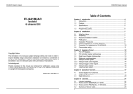
The CN2 pin assignment is as shown in Figure 2-2
Connector Pin Assignment of EX-98354
The CN2 is a 40-pin FRC connector and can be converted to 37-pin D-type
connector by using converting cable attached in the package.
There are two connectors labeled “CN2” and “CN3”. The CN3 connector is a 37-pin
D-type connector and CN2 connector is a 40-pin FRC connector.
The pin assignment of the CN2 (40-pin FRC connector) includes 16 digital
input and output signals
The pin assignment of the CN3 (37-pins D-type connector) includes 12 timer/counter
input and output signals
The CN3 pin assignment is as shown in Figure 2-1
CN3
ECLK_1
GAET_1
COUT_1
ECLK_2
GAET_2
COUT_2
ECLK_3
GAET_3
COUT_3
ECLK_4
GAET_4
COUT_4
ECLK_5
GAET_5
COUT_5
ECLK_6
GAET_6
COUT_6
ECLK_7
1
20
2
21
3
COUT_7
22
ECLK_8
23
GAET_8
24
COUT_8
4
5
6
25
ECLK_9
26
GAET_9
7
8
1
DI_1
2
DI_2
3
DI_3
4
DI_4
5
DI_5
6
DI_6
7
DI_7
8
DI_8
9
DI_9
10
27
COUT_9
DI_10
11
28
ECLK_10
DI_11
12
DI_12
13
DI_13
14
COUT_11
DI_14
15
COUT_12
DI_15
16
GND
17
DO_0
18
DO_1
19
9
10
29
11
30
12
31
13
32
14
GAET_10
COUT_10
33
GND
34
GND
15
16
35
GND
36
+5V
37
+5V
17
18
19
GAET_7
DI_0
20
DO_2
21
DO_3
22
DO_4
CN2
23
DO_5
24
DO_6
25
DO_7
26
DO_8
27
DO_9
28
DO_10
29
DO_11
30
DO_12
31
DO_13
32
DO_14
33
DO_15
34
GND
35
GND
36
+5V
37
+5V
Converting cable
DI_0
DI_1
DI_2
DI_3
DI_4
DI_5
DI_6
DI_7
DI_8
DI_9
DI_10
DI_11
DI_12
DI_13
DI_14
DI_15
GND
DO_0
DO_1
1
3
5
7
9
11
13
15
17
19
21
23
25
27
29
31
33
35
37
39
2
4
6
8
10
12
14
16
18
20
22
24
26
28
30
32
34
36
38
40
40-pin FRC connector
Figure 2-2 Pin Assignment of EX-98354 connector CN2
Legend:
Figure 2-1 Pin Assignment of EX-98354 connector CN3
DO_n: Digital output channel #n (n= 0 ~ 15)
DI_n: Digital input channels #n (n= 0 ~ 15)
Legend:
GND: Ground return path of digital input/output channels
ECLK_n: Clock input channel #n(n= 1 ~ 10)
+5V: Non-isolated +5V DC output
GATE_n: Gate control input channel #n (n=1 ~ 10)
COUT_n: Count output channel #n (n=1 ~ 12)
:GND: Ground return path of counter/time channels
+5V: Non-isolated +5V DC output
11
12
DO_2
DO_3
DO_4
DO_5
DO_6
DO_7
DO_8
DO_9
DO_10
DO_11
DO_12
DO_13
DO_14
DO_15
GND
GND
+5V
+5V