1
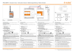
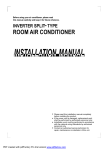
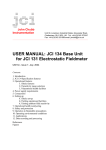
INSTALLATION SCHEMATIC
Main Meter
PHOTOVOLTAIC PLANT INTO THE MAIN CIRCUIT BREAKER
N
ELIOS4YOU &
ELIOS4YOUSMART
Generation
meter
N
Quick
L
L
K
L
L
Green point and the direction
of the arrow K
L towards
the main circuit breaker
Main CT
(yellow label)
Common relay
K
Main
Circuit Breaker
IN+10 V
Ctrl
GND
X
X X
Guide
Generation CT
(white label)
Alarm 2 -NO
Alarm 1 -NO
L
N
Load
Relay
normally
open
13 14 15 16 17 18 19 20 21 22 23 24
ID Code label
ID CODE:YYYYY
Fig.1
123456789XXXXX
The Elios4you family of products are wireless devices designed to monitor and manage
single-phase photovolatic installations via the Elios4you APP. Maximum monitored power
10kW. The transmitter measures the energy generated of the PV plant, exchanged with
the grid, the household consumption and the self-consumption. In the “Smart” version
it allows to optimize the self-consumption by turning programmed loads with additional
Plug and Switch accessories.
1A
Hole for CONFIG
button
SIG + Generation CT - Red color
Shield = optional Generation CT
SIG - Generation CT - Black color
EN
SIG - Main CT - Black color
Shield = optional Main CT
SIG + Main CT - Red color
N L 3 4 5 6 7 8 9 10 11 12
X X X X
Elios4you
Main Meter
Generation
meter
PHOTOVOLTAIC PLANT DIRECTLY WIRED INTO THE MAINS METER
N
Elios4you
Smart
N
ID CODE:YYYYY
123456789XXXXX
ID Code label
ID CODE:YYYYY
123456789XXXXX
L
L
K
L
L
Green point and the direction
of the arrow K
L towards
the main circuit breaker
Main CT
(yellow label)
Common relay
K
Current
transformers pair
Main
Circuit Breaker
IN+10 V
Ctrl
GND
X
X X
Alarm 2 -NO
Alarm 1 -NO
L
N
Generation CT
(white label)
Load
READ AND KEEP THESE INSTRUCTIONS FOR REFERENCE
Hole for CONFIG
button
ID Code label
ID CODE:YYYYY
123456789XXXXX
1A
Fig.2
13 14 15 16 17 18 19 20 21 22 23 24
SIG + Generation CT - Red color
Shield = optional Generation CT
SIG - Generation CT - Black color
SIG - Main CT - Black color
Shield = optional Main CT
SIG + Main CT - Red color
N L 3 4 5 6 7 8 9 10 11 12
X X X X
4-noks SRL - Via Per Sacile, 158 - Francenigo di Gaiarine (TV) - Italy
Tel. +39 0434 768462 - Fax +39 0438 694617 - [email protected] - www.4-noks.com
+05T408021R1.3 – E4U - E4U-S Quick Guide EN 15/06/2015
Relay
normally
open
Product identification:
ATTENTION
ATTENTION: Installation must be completed by
qualified personnel only. The customer (builder,
developer or installer ) accepts all liability and
risk relating to the configuration of the product
to achieve the expected results in relation to the
specific installation. Any deficiencies in the acknowledgment of the instructions may lead to
malfunctions and / or damage to the devices,
to which 4-NOKS cannot be held responsible.
The responsibility of 4-NOKS in relation to the
devices manufactured is regulated by the general terms & conditions. Be careful to ensure all
works being carried out are completed by qualified personnel, during which, no power is being
supplied to the devices.
this document refers to following devices:
Code
E4U
E4U-S
Elios4you
Elios4youSmart
All models are compliant to directive
2004/108 CE - 2006/95 CE - directive
99/5 CEE
The appliance (or the product) must
be disposed of separately in
accordance with the local regulations
regarding disposal.
4-NOKS hereby declares that these products
conform to the essential requirements and to all
relevant specifications established by Directive
1999/5/CE. The declaration of conformity may
be consulted on the website: www.4-noks.com.
INSTALLATION
ATTENTION
ATTENTION: in order to protect against overvoltages
and short circuits, the device must be powered via
an easily accessible and externally located sectioning
breaker, thermal magnetic breaker or 230 Vac 1 A fuse.
ATTENTION: Before installing Elios4you, remove
the label with device credentials and attach below
(or keep in a safe place) for future reference and/or
monitoring via the 4-Cloud Dashboard (web-portal)
www.4-cloud.org
ID CODE: 00000
Register on:
www.4-cloud.org
and associate your device
with USER: XXXXXXXX
3. Open the App and start the Wizard Configuration, following the steps visible on your smartphone/
tablet (read the Elios4you APP Quick Guide for further information)
4. Set correct parameters for your PV system and your energy provider using the App menu:
-- Press
-- Select
“Menu” button
“Parameter Settings”
-- Select “Energy Management” and set values
-- Press OK when finished to save new values.
-- Press
“Home” button to to go the “Energy Performance” page
ATTENTION
WARNING: if the generation energy LED
does not
blink when the PV installation is producing energy, it
is necessary to invert the Generation CT orientation
by swapping the connection of the wires of Elios4You
(terminals 7 and 9).
WARNING: if the LEDS
detect the wrong
energy flow (“sold” energy when it should report a
situation of “purchased” energy or vice versa), it is
necessary to invert the mains CT (yellow label) by
swapping the connection of the wires of Elios4You
(terminals 10 and 12).
WARNING: Ensure that the positioning of the
Generation & Mains CTs are correct to the wiring of
the property. Otherwise the resulting measurements
may not be reliable. Ensure the Mains CT clamp
is positioned after the Mains Meter, but before the
Consumer Unit. Taking into account any Henley Blocks
/ Split Junctions.
WARNING: Alterations to the length of CT cables
may cause increases in marginal errors during
measurements. We do not recommend such alterations
of the device.
-- Check that the energy “Consumption”
have in the property.
has a similar value to that from the inverter
value relative to the real-time consumption you
1. Open the Elios4You APP
2. Press Menu Button
--> Red Cap --> Activate Red Cap --> Confirm
SMART PLUG / SWITCH PAIRING
ATTENTION: When pairing devices for the first time, keep devices within close range to the Elios4you
transmitter. The devices can then be moved around to required position after pairing is complete.
The Smart Plug/Switch does not need to be close to the Wi-Fi router, as the Smart Plug/Switch
communicates using ZigBee RF (directly to the Elios4you transmitter) and not through Wi-Fi.
1. Verify that your smart device (smartphone/tablet) is within radio range of the Wi-Fi and/or
Elios4you.
2. Install the Plug/Switch to be paired to Elios4you.
3. Make sure that the Plug/Switch is not paired with a network already (Red LED flashing), otherwise
perform the disassociation before continuing (see manual for Smart Plug/Switch).
4. Select Menu icon in the Elios4you App
App --> Red Cap --> Add Smart Plug.
5. Carefully follow the Wizard in the Elios4you App.
6. Once complete, go back to the Home Screen of the App
select the Consumption icon:
taking you to the Consumption Details page where you will see icons for the management of
individual appliances .
7. To modify the settings of individual Plug/Switch, select the corresponding icon
NOTE: repeat the above procedure for the installation of additional Smart Plug/Switch.
Elios4you Front Panel Icons
Blink frequency
proportional to the
amount of generated
energy of the pv plant
(red)
Blink frequency
proportional to the
amount of energy
exchanged with the grid
(red)
If ON: energy currently
being purchased from
the grid
(red)
If ON: energy currently
being sold to the grid
(green)
ATTENTION: Within 1 minute of the pairing procedure, you will be able to see the Smart Plug/Switch
state in the Elios4you App.
SMART SWITCH
Power supply
(green)
Wi-Fi on
(green)
General alarm or
failed attempt to
get connected to
the smart device
(red)
LED
Button
SMART PLUG
LED
76
Not used
(green)
TROUBLESHOOT
Solutions
1. I can’t see my PV system energy generation in the App’s
Home Page
a. Change the Generation CT clamp (white label) orientation, by inverting the green dot (or the arrow direction inside the clamp)
to the opposite direction.
b. Check that the Generation CT clamp (white label) is only clamped around the PV Live cable (not including the Neutral cable).
c. Check that the CT clamp core is not broken or cracked inside (you may hear a buzzing noise).
d. Check that the Generation CT clamp (white label) is properly closed - be sure not to apply excessive force.
2. The energy generation visible
on the App is definitely less
than the value read from the
inverter
a. Ensure that the Elios4you transmitter is powered from the same Live phase as the Mains CT clamp (yellow label).
b. Check that the Generation CT clamp (white label) is properly closed - be sure not to apply excessive force.
3. The Consumption line has
the same shape as the Generation line in the graph
a. Ensure that the Mains CT clamp (yellow label) is clamped over the Mains Live phase cable after the Mains Meter and before
the Consumer Unit and/or any Henley Block. Failing to do so will not give an accurate measure of total consumption.
b. Ensure that the Neutral cable is not included within the Generation / Mains CT clamps.
c. Check that the CT clamp cores are not broken or cracked inside (you may hear a buzzing noise).
7. The App shows a consumption value much higher than I
would expect.
ATTENTION: Be sure to configure the Smart
Plug/Switch correctly, as per the instructions
from specific appliance manufacturers.
ATTENTION: Configuring Elios4you in “Indirect Mode” grants access through the broadband Router/
AP, allowing all data to be sent to the 4-Cloud, visible remotely through the Elios4you APP (when
4-Cloud is activated) and also via the 4-Cloud Dashboard (web-portal). Go to http://www.4-cloud.
org and follow the instructions to register your device. Using the credentials on the label provided
(see left).
Problem
4. It seems that the Consumption values are only being
shown in the “Grid” icon
5. I can never see “Purchased
Energy” in my system
6. During the night the consumption is zero, while during the day consumption is
always more than the expected value
DO NOT CONNECT THE SMART PLUG/
SWITCH TO:
- medical equipment: the involountary deactivation can cause life-threatening situations
- devices that can cause damage, injury or fire in
case of accidental activation (eg. irons)
- appliances that can be damaged by turning on
/ off frequently
- appliances that cannot be interrupted
- appliances that require a continuous current
supply.
ATTENTION: Always seek advice from the
manufacturer or user manual of the appliance
if it is suitable to control via radio plug or timer.
5. Ensure the data values are correct:
-- Check that energy “Generation” value
ATTENTION: If you are configuring the Elios4you APP
via the Router/AP, data will be visible via the 4-Cloud
Dashboard after approximately 1 hour from configuration.
ATTENTION
1. Secure the device on a DIN rail, following the connections showed in the previous scheme (Fig.1
and Fig. 2).
2. Once the device is installed and powered on, download the free Elios4you APP on your own
smart device (smartphone or tablet) from Playstore (Android) or App Store (iOS)
MANAGING APPLIANCES VIA
ELIOS4YOUSMART OR RED-CAP ACCESSORY
a. Ensure that the Mains CT clamp (yellow label) is clamped over the Mains Live phase cable after the Mains Meter and before
the Consumer Unit and/or any Henley Block. Failing to do so will not give an accurate measure of total consumption.
a. Change the Mains CT clamp (yellow label) orientation, by inverting the green dot (or the arrow direction inside the clamp)
to the opposite direction.
b. Ensure that the Mains CT clamp (yellow label) is clamped over the Mains Live phase cable after the Mains Meter and before
the Consumer Unit and/or any Henley Block. Failing to do so will not give an accurate measure of total consumption.
Button
GREY
Shows the OFF state (off)
for both the manual mode
and/or automatic mode.
YELLOW
Shows the ON state (on)
for both the manual mode
and/or automatic mode.
RED
Shows the OFFLINE state,
meaning the plug/switch is
off from the mains, or is out
of radio range.
TECHNICAL SPECS
General Characteristics
nr. 8 led of functionality diagnostic; Parameter configuration with Tablet
Radio Characteristics
Wi-Fi 802.11b; Access point (AP) Station (STA),B; Output Power 15 +- 1 dBm
Red Cap (only Elios4you Smart); ZIGBEE Home Automation Profile (HA1.2)
2405 MHz ÷ 2480 MHz; IEEE 802.15.4 compatible; Nominal transmission Power +10dBm; Internal PCB Antenna
Power Supply
230Vac +- 20% 2 W
Internal Memory
Historical data up to two months with sampling every 15 minutes
Alarms
External alarm: free contact connected to the inverter or auxiliary contact breakers; Lack of production in absence of
data after 4 hours in the central time zone (from 10.00 to 14.00)
Connections
Screw terminals for 230 V ac; Screw terminals for CT; Screw terminals for signal input alarm
Dimensions of C.T. hole
Internal diameter: 16 mm
Antenna
Wi-Fi external antenna SMA RP connector.
Environment Parameters
Operting temperature 0 + 50°C; International Protection IP45
CE Declarations of
Conformity
Compliant with directives 2004/108 CE (Directive EMC) 2006/95 CE (Low Voltage Directive)/ 99/5 CEE (Radio
Equipment Directive). Standards and/or technical specifications applied: ETSI EN 300 328v1.8.1:2012-06; ETSI EN
301 489- 17v2.2.1:2012; ETSI EN 301 489-1v1.9.2:2011; EN 61326-1:2013; EN 60950-1:2006 + A11 (2009)
a. Ensure that the Mains CT clamp (yellow label) is clamped over the Mains Live phase cable after the Mains Meter and before
the Consumer Unit and/or any Henley Block. Failing to do so will not give an accurate measure of total consumption.
a. Change the Mains CT clamp (yellow label) orientation, by inverting the green dot (or the arrow direction inside the clamp)
to the opposite direction.
DIFFERENT STATES OF THE SMART PLUG/SWITCH IN THE APP:
Dimensions (mm)