1
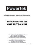
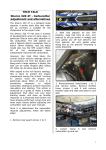
Power
t
ekUSI
nc.7Thi
r
dSt
r
eet
,Hol
br
ook NY1
1
7
41 USA
T
el
:+16316156279 Fax
:+19732735893
power
t
ekus
.
com
Emai
l
:i
nf
o@power
t
ekus
.
com www.
PEM’s Rogowski Current Waveform Transducers combine high bandwidth, safety, and the minimum
disruption to the circuit under test. These instructions should be followed whenever the unit is used.
They are intended to help you obtain the best and safest performance from the transducer.
ACCURACY (5 to 100% full scale)
Within the limits of bandwidth and low frequency noise that are specified on the relevant CWT
specification sheet.
Calibration:
Normally ±0.2% (traceable to UKAS) with the
conductor central in the CWT loop. See the calibration
certificate for more details.
±1% typ. variation of accuracy with conductor position
in the loop (see ‘Obtaining The Best Measurement’)
±0.05% typ.
Positional accuracy:
(Standard coils)
Linearity:
POWER SUPPLY
The CWT can be powered by both battery and an external DC voltage. With the external DC supply
present the batteries are inoperative.
Battery type:
Battery life:
DC socket type:
DC voltage:
DC quiescent supply current:
4 (four) 1.5V AA alkali
70 hrs typ.
2.1 or 2.5mm jack socket – polarity indicated on front of
CWT
12 to 24V DC (±10%)
30mA (@12V DC) , 30mA (@ 24V DC)
When specified with rechargeable batteries the CWT operates directly from the batteries when there
is no DC supply present and is powered directly from the DC supply when present. With the DC
supply present the rechargeable batteries are permanently trickle charged.
Battery type:
Battery life:
Recharge time:
DC socket type:
DC voltage:
DC quiescent supply current:
4 (four) 1.2V NiMH rechargeable batteries
30 hrs typ. (based on a 1400mAH cell)
40 hrs typ.
2.1 or 2.5mm jack socket – polarity indicated on front of
CWT
12 to 24V DC (±10%)
70mA (@12V DC) , 70mA (@ 24V DC)
OUTPUT
Maximum output voltage:
Output cable:
Minimum output loading:
±6V (corresponding to ±Peak Current Rating of CWT)
OPERATING TEMPERATURE RANGES
Rogowski coil and cable
Integrator electronics
March 2003
-20oC to 100oC
0 to 40oC
2
1. Rogowski coil (loop)
2. ‘Free end’ of the Rogowski
coil
3. Ferrule (the connecting
mechanism for closing the
Rogowski coil).
4. Cable connecting the
Rogowski coil to the
integrator electronics
5. Socket for external DC
supply
6. LED status indicator for
external DC supply
7. Enclosure for the integrator
electronics
8. Output BNC socket
9. 4 x AA batteries
10. LED indicator
- GREEN - CWT is ON
- RED – low battery
11. Push button ON / OFF
switch
March 2003
3
Throughout this instruction sheet there are a number of warnings which must be observed to ensure
safe operation of this unit. These warnings are identified by the following symbol:
!
PEM accepts no responsibility for any accidents or damage resulting from careless use, or nonobservance of these instructions.
THE ROGOWSKI COIL
!
The integrity of the insulation around the Rogowski coil itself should be VISUALLY
INSPECTED before use, and the unit should NOT BE USED if there are signs of damage.
!
When bending the flexible coil around a conductor, avoid tight bends and sharp edges that
could damage the coil.
!
!
The voltage rating (safe PEAK working voltage) is clearly labelled on the coil. The rating is
normally 10kV peak (red coil) but can also be 5kV peak (yellow coil) and 2kV peak (green
coil). The removable silicone sleeve supplied with the coil increases the voltage rating of
yellow and green coils to 10kV peak and provides mechanical protection.
The ratings are derived from the following standard test. All coils supplied by PEM
including the ferrule connecting the coil to the cable are flash tested for 1 minute at
15kVrms using a 50Hz sinewave. Coils rated at 10kV peak (red coils) are tested without
the 10kV sleeve; coils rated below 10kV peak (yellow and green coils) are tested with the
10kV sleeve fitted.
!
For additional safety it is recommended that the ferrule is not situated in direct contact with
conductors at voltages higher than 8kV peak. See also “Obtaining the Best Measurement”.
!
The voltage ratings are appropriate for intermittent use of the CWT as a test instrument
and not for continuous use in a permanent installation.
For permanent installation the coil should be situated such that corona, which would
eventually damage the coil insulation, cannot occur. For information regarding permanent
installation of PEM’s Rogowski coils on high voltage equipment please consult PEM.
!
Voltage ratings are only valid if the ‘free-end’ of the coil is fully inserted into the socket, and
remains fully inserted during use.
The ‘free–end’ will be fully inserted when the user feels the free-end of the coil engage with
the internal click-in mechanism inside the ferrule.
Visual indication that the coil mechanism is fully inserted is provided by the black cable
marker situated near the end of the coil, as shown opposite
March 2003
4
10kV peak
10kV peak
!
"
!
If the coil is to be left in-situ for any period of time or is used in an environment where the
coil is subject to vibration the locking nut should be engaged as shown in the diagram
below.
To lock
the jaws
The locking mechanism must not be actuated at temperatures below 0oC
Care must be taken not to over-tighten the locking nut.
THE INTEGRATOR
!
The CWT must only be used with oscilloscopes or monitoring equipment which have
their BNC INPUTS PROPERLY GROUNDED.
March 2003
5
!
!
Before installing the CWT and taking a measurement refer to SAFETY AND PRE-USE
CHECKS to ensure safe operation of your CWT
Do not fit a Rogowski coil to a live circuit; always de-energise the circuit first.
1. Connect the BNC plug on the output cable of the transducer to your oscilloscope or current
monitoring equipment. The CWT must only be used with oscilloscopes or monitoring equipment
which have their BNC INPUTS PROPERLY GROUNDED.
2. Having carried out the VISUAL INSPECTION of the Rogowski coil, un-clip the coil and wrap it
around the de-energised conductor under test.
3. Insert the free-end of the coil fully inside the ferrule and lock the jaws if necessary.
4. Re-energise the conductor.
5. The CWT is switched ON by pressing and releasing the ON push button, and is turned OFF by
depressing the button fully; the LED indicates that the CWT is ON when the LED is GREEN.
6. – EITHER - Standard alkali battery supplied CWT units
Four 1.5V AA alkali batteries provide about 70 hours operation. Battery voltage is continuously
monitored; healthy batteries are indicated by the GREEN LED. If the LED is RED the batteries are
delivering less than 2V and must be replaced by removing the sliding battery door in the back
cover of the integrator enclosure.
The units can also be powered by an external DC supply. The DC voltage can be between 12 and
24V (±10%). When the DC supply is present a RED indicating LED adjacent to the socket is
illuminated. With the DC supply present the batteries are inoperative.
- OR - Re-chargeable battery CWT units When fully charged four 1.2V AA NiMH rechargeable cells provide about 30hrs operation. Battery
voltage is continuously monitored; healthy batteries are indicated by the GREEN LED. If the LED
is RED the batteries are delivering less than 2V and must be recharged.
The units can also be powered by an external DC supply. The DC voltage can be between 12 and
24V (±10%). When the DC supply is present a RED indicating LED adjacent to the socket is
illuminated. When the DC supply is present the batteries are inoperative and the external DC
voltage powers the integrator. In addition when the DC supply is present (regardless of whether
the integrator is on or off) the rechargeable batteries are trickle charged.
7. After switch-on the CWT requires a settling down time to attain its quiescent state before
providing correct current measurement. The time, which depends on warm-up and low frequency
bandwidth, can be as long as 2 minutes.
March 2003
6
The Rogowski coil should be positioned so that the conductor under test is encircled by the coil but is
not adjacent to the cable attachment (see picture below). The arrows across the coil show the
direction a positive current should pass through the coil loop in order to obtain a positive output
voltage. The CWT has been calibrated with the conductor near the centre, and this is the ideal
position.
I
c u rre n t in to
page
K E EP C O N D U C T O R S
AW AY FRO M
SHADED AREA
The sensitivity of the CWT to currents that do not pass through the coil is very small, provided that
such currents are no greater than the CWT’s rating or such currents are relatively distant from the
coil. In the vicinity of a multi-turn inductor the ‘H’ field is far stronger than from a single conductor
carrying the same current, and such positions should be avoided.
Similarly if there is a surface with a high voltage very close to the coil, and the voltage is subject to
high rates of change (e.g. several 100 V/µs) or high frequency oscillations in the MHz range, then
measurement error can arise due to capacitive coupling to the coil.
As a check on any unwanted response to adjacent fields, it is wise to display the output of the CWT
when close to (but not encircling) the conductor whose current is to be measured. This will reveal the
magnitude of any unwanted response to currents close to but outside the coil.
EMISSIONS
PEM’s Rogowski current waveform transducers are certified to: BS EN 50081-2:1994
IMMUNITY
PEM’s Rogowski current waveform transducers are certified to: BS EN 50082-2:1995
OUTPUT CABLES
A 0.5m BNC-BNC output cable is supplied with the unit but a longer cable can be used. The cable
should be a 50 ohm singly screened co-axial cable. Although at present this has not been included in
the immunity tests and may decrease RF noise immunity, PEM does not consider the use of
extension cables to be problematic from the noise viewpoint. PEM has conducted tests using a 25m
extension and no discernible attenuation of measured current signal has occurred although, as is to
be expected, there is an increased measurement delay of 5ns/m.
March 2003
7
Power
t
ekUSI
nc
.7Thi
r
dSt
r
eet
,Hol
br
ook NY1
1
7
4
1 USA
T
el
:+
163
16
1
56279 Fax
:+
19
732735893
E
ma
i
l
:
i
n
f
o
@p
o
w
e
r
t
e
k
u
s
.
c
o
m
w
w
.
p
o
w
e
r
t
e
k
u
s
.
c
o
m
w
w
w
.
p
o
w
e
r
t
e
k
u
s
.
c
o
m
E
ma
i
l
:
i
n
f
o
@p
o
w
e
r
t
e
k
u
s
.
c
o
m w