1
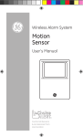
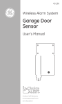
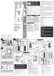
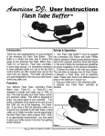
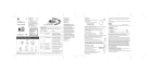
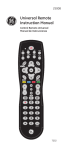
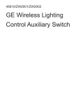
19230-2
Wireless Door Chime
User’s Manual
Chime
Push Button
Thank you on your purchase
of the Wireless Door Chime.
Before installation, please
read this manual carefully
and keep for future reference.
1
Required Tools
• Flathead screwdriver
• Drill
• 1/16” drill bit
• 5/32” drill bit
• Phillips screwdriver
Included Hardware:
• 2 – Plastic anchors
• 4 – Screws
• 1 – Double sided Tape
• 1 – 12 Volt battery
Battery Installation:
Chime Unit:
1. Make sure the Chime power is switched to the “OFF”
position.
2. Remove battery cover by pressing the tab in the
direction of the arrow and lifting at the same time.
3. Install 2 “AA” batteries noting the battery orientation
inside the battery compartment.
4. Replace battery cover.
Push Button:
1. Remove battery cover by using a small flat screwdriver.
2. Insert flat screwdriver in at the bottom of the Push
Button to release the tab.
3. While the flat screwdriver is inserted at the bottom of the Push Button,
press downwards to separate the battery cover from the Push Button.
4. Remove plastic tab in between the 12V
battery and contact tab to allow button
to operate.
2
Linking the Push Button to the Chime Unit:
1. Switch the Chime power to the “ON” position.
The red LED will begin blinking slowly.
2. Within 10 seconds of turning on the power,
press the push button. The LED on the chime
will blink rapidly and turn off. The Chime and
Push Button have been successfully linked.
3. To test, press the Push Button and the Chime
Unit should chime.
Press
Press
Note: If linking fails or you change the batteries
or turn the Chime Unit off and back on, you will have to re-link the Push
Button to the Chime Unit. Perform steps 1 and 2 in the “Linking the Push
Button to the Chime Unit.”
Low Battery Indicator:
The Chime Unit has a low battery indicator feature. When the battery is
at 25 percent capacity, the LED on the Chime Unit will begin to blink and
will continue to blink each time the Push Button is depressed. Replace the
batteries and the LED will stop blinking.
(You will have to re-link the Push Button to the Chime Unit)
Installing the Push Button:
1. Push Buttons are mounted at the same height as the door knob or handle,
between 36” – 44” above the floor. Remove the old push button and use
this location to install your new Push Button.
2. Before mounting the Push Button run a test. Place the Push Button as
close as you can to where you would install it. Place the Chime as close as
possible to its installation site. Press the Push Button and see if the Chime
rings. If the Chime does not ring see – Troubleshooting.
*Remember: Button should be no farther away than 150 ft from the
chime; and test before installation.
3
Installation using the provided screws:
1. Remove the old push button and use
this location to install your new Push
Button.
2. Remove the battery cover as
described in the installation of the
battery.
3. Use the battery cover as a template to
mark the position of the screws.
4. Using a 1/16th inch drill bit, drill a pilot
hole for each screw.
5. Using a Phillips head screwdriver,
mount the back cover using the
screws provided. (Note: The back
cover has an arrow and the word “Up”
embossed on the inside of the cover. Position the back cover with the
arrow pointing upwards and the word “Up” is at the top)
6. Press the Push Button on to the back cover by inserting the top of the
Push Button onto the top of the back cover first and then pressing on the
bottom of the Push Button to snap the bottom of the Push Button into
place.
Installation using the provided Double Sided Tape:
1. Clean the surface where you would like to mount the Push Button and
the back of the Push Button. Use a mixture of 50/50 water to isopropyl
alcohol.
2. Remove the battery cover as described in the installation of the battery.
3. Remove the backing from one side of the double sided tape and press it
onto the back of the back plate of the Push Button.
4. Remove the backing from the other side of the double sided tape and
press the back plate to the cleaned mounting surface. (Note: The back
cover has an arrow and the word “Up” embossed on the inside of the
cover. Position the back cover with the arrow pointing upwards and the
word “Up” is at the top)
4
5. Press the Push Button on to the back
cover by inserting the top of the Push
Button onto the top of the back cover
first and then pressing on the bottom
of the Push Button to snap the bottom
of the Push Button into place.
Installing the Chime Unit:
Note: Avoid mounting the Chime Unit on metal surfaces, as this may result in
reduced range of transmission. The Chime Unit should also be mounted no
farther than 150 feet from the Push Button.
No further than 150 feet away
1. Select a mounting location that is within the
150ft. range.
2. Use the supplied Chime template to mark
mounting holes.
a.If mounting to sheetrock:
i. Using a 5/32nd inch drill bit, drill holes at the marked locations.
ii. Insert the two wall anchors supplied
iii.Screw in the two screws supplied leaving a ¼” of the
1/4”
screw extended out from the mounting surface. (See
diagram)
iv. Place the Chime Unit’s keyholes over the screws and gently press
downwards to secure Chime Unit.
b. If mounting onto or into wood:
i. Using a 1/16th inch drill bit, drill pilot holes at
the marked locations.
ii. Screw in the two screws supplied leaving a ¼”
of the screw extended out from the mounting
surface. (See diagram)
iii. Place the Chime Unit’s keyholes over the screws
and gently press downwards to secure Chime Unit.
5
Chime Template
6
Troubleshooting:
1. Make sure the batteries are installed according to the polarity markings
inside the battery compartment on the Chime Unit.
2. Make sure the battery is installed according to the polarity markings
inside the battery compartment on the Push Button.
3. Try installing new batteries.
4. Make sure the Chime Unit is no farther than 150ft. from the Push Button.
5. Try moving the Chime Unit to a different location that is within the 150ft.
range.
6. Make sure the Push button is not mounted on a metal surface, on or near
metal studs, or near the floor. (Push Button should be mounted 36” to 44”
from the floor)
7. Make sure the Push Button and the Chime Unit is properly linked. (Refer to
the section “Linking the Push Button to the Chime Unit”)
Functional range may be adversely affected by one or more of the
following factors:
• Weather
• Radio Frequency Interference
• Low Transmitter Battery (Push Button)
• Obstruction between Push Button and Chime Unit
FCC Statement:
This device complies with Part 15 of FCC rules. Operation is subject to the
following conditions.
1. This device may not cause harmful interference.
2. This device must accept interference that may cause undesired operation.
FCC NOTE:
The manufacturer is not responsible for any radio or TV interference caused
by unauthorized modifications to this equipment. Such modifications could
void the user’s authority to operate the equipment.
NOTE: This equipment has been tested and found to comply with the limits
for a Class B digital device, pursuant to Part 15 of the
7
FCC Rules. These limits are designed to provide reasonable protection
against harmful interference in a residential installation. This equipment
generates, uses and can radiate radio frequency energy and, if not
installed and used in accordance with the instructions may cause harmful
interference to radio communications. However, there is no guarantee that
interference will not occur in a particular installation. If this equipment does
cause harmful interference to radio or television reception, which can be
determined by turning the equipment off and on, the user is encouraged to
try to correct the interference by one or more of the following measures:
--Reorient or relocate the receiving antenna.
--Increase the separation between the equipment and receiver.
--Connect the equipment into an outlet on a circuit different from that to
which the receiver is connected.
--Consult the dealer or an experienced radio/TV technician for help.
10/10/11
is a trademark of the General Electric Company and
is used under license to Jasco Products Company LLC,
10 E. Memorial Road, Oklahoma City, OK 73114.
This Jasco product comes with a limited lifetime warranty.
Visit www.jascoproducts.com for details.
8