1
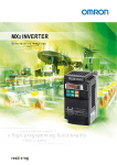
Multi-function Compact Inverter
MX2-Series
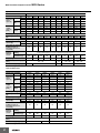
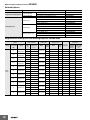
Function Specifications
Control
Function name
Enclosure ratings *1
Control method
Output frequency range *2
Frequency precision *3
Frequency setting resolution
Voltage/Frequency
characteristics
Overload current rating
Instantaneous overcurrent
protection
Acceleration/Deceleration time
Carrier frequency adjustment range
Starting torque
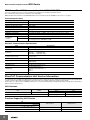
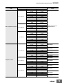
Multi-function input
Analog input
Pulse input
Multi-function output
2 points (P1/EDM, P2; selectable from 43 functions)
Relay output
1 point (1c contact: MC, MA, MB; selectable from 43 functions)
Protective functions
Communications Output signal
Input signal
Frequency settings
RUN/STOP command
Analog output (Frequency monitor) 1 point (AM terminal: Voltage 10 bits/0 to 10 V) (Frequency, current selectable)
Pulse output
1 point (MP terminal: 32 kHz max., 0 to 10 V)
RS-422
RJ45 connector (for Digital Operator)
RS-485
Control circuit terminal block, Modbus communication (Modbus-RTU)
USB
USB1.1, mini-B connector
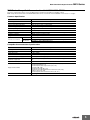
Other functions
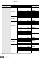
General specifications
200% of the value of heavy load rating (CT)
0.01 to 3600 s (linear/curve selection), acceleration/deceleration 2 setting available
2 to 15 kHz (with derating)
200%/0.5 Hz (sensorless vector control)
Starts at a frequency lower than that in deceleration via the STOP command, at a value set lower than
that during operation, or via an external input. (Level and time settable).
Overcurrent, overvoltage, undervoltage, electronic thermal, temperature error, ground fault overcurrent
at power-on status, rush current prevention circuit, overload limit, incoming overvoltage, external trip,
memory error, CPU error, USP error, communication error, overvoltage suppression during
deceleration, protection upon momentary power outage, emergency cutoff, etc.
Digital Operator
External analog input signal: 0 to 10 VDC/4 to 20 mA, Modbus communication (Modbus-RTU)
Digital Operator
External digital input signal (3-wire input supported), Modbus communication (Modbus-RTU)
7 points (Selectable from 59 functions)
2 points (Voltage FV terminal: 10 bits/0 to 10 V, Current FI terminal: 10 bits/4 to 20 mA)
1 point (RP terminal: 32 kHz max., 5 to 24 VDC)
External DC injection braking
AVR function, V/f characteristics switching, upper/lower limit, 16-step speeds, starting frequency
adjustment, jogging operation, carrier frequency adjustment, PID control, frequency jump, analog gain/
bias adjustment, S shape acceleration/deceleration, electronic thermal characteristics, level adjustment,
restart function, torque boost function, fault monitor, soft lock function, frequency conversion display,
USP function, motor 2 control function, UP/DWN, overcurrent control function, etc.
Ambient temperature
-10 to 50°C (However, derating is required).
Ambient storage temperature
-20°C to 65°C (short-time temperature during transport)
Humidity
20% to 90% RH (with no condensation)
Vibration
5.9 m/s2 (0.6G), 10 to 55 Hz
Location
Options
International standard
Specifications
Open type (IP20)
Phase-to-phase sinusoidal modulation PWM
0.10 to 400 Hz (or 1,000 Hz in the high-frequency mode; restrictions apply)
Digital command: ±0.01% of the max. frequency, Analog command: ±0.2% of the max. frequency (25°C±10°C)
Digital setting: 0.01 Hz, Analog setting: One-thousandth of the maximum frequency
V/f characteristics (constant/reduced torque)
Sensorless vector control, V/f control with speed feedback
Heavy load rating (CT): 150%/60 s
Light load rating (VT): 120%/60 s
EMC directive
Low voltage
EC
directive
directive
Machinery
directives
UL/cUL
At a maximum altitude of 1,000 m; indoors (without corrosive gases or dust)
DC reactor, AC reactor, radio noise filter, input noise filter, output noise filter, regenerative braking unit,
Braking Resistor, EMC noise filter, etc.
EN61800-3: 2004
EN61800-5-1: 2003
IEC60204-1 Stop Category 0, EN IEC61800-5-2 (STO), EN ISO13849-1: 2008 (PLd), ISO13849-1: 2006
(PLd)
UL508C
Note: 1. The applicable motor is a 3-phase standard motor. For using any other type, be sure that the rated current does not exceed that of the Inverter.
2. Output voltage decreases according to the level of the power supply voltage.
3. The braking torque at the time of capacitor feedback is an average deceleration torque at the shortest deceleration (when it stops from
50 Hz). It is not a continuous regeneration torque. Also, the average deceleration torque varies depending on the motor loss. The value
is reduced in operation over 50 Hz.
*1 Protection method complies with JEM 1030.
*2 To operate the motor at over 50/60 Hz, contact the motor manufacturer to find out the maximum allowable speed of revolution.
*3 For the stable control of the motor, the output frequency may exceed the maximum frequency set in A004 (A204) by 2 Hz max.
3