1
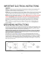
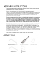
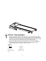
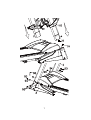
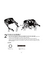
SPT0064
XT285 Treadmill
OWNER’S MANUAL
Please carefully read this entire manual before operating your new treadmill
TABLE OF CONTENTS
Important Safety Instructions
2
Important Electrical Instructions
3
Important Operation Instructions
4
Assembly Instructions
5
Folding/Transport Instructions
10
Features
11
Console Operation
12
Programmable Features
15
Using Heart Rate Transmitter
20
General Maintenance
22
Exploded View Diagram/Parts List
27
XT285/SPT0064_Ver. A
1
IMPORTANT SAFETY INSTRUCTIONS
WARNING - Read all instructions before using this appliance.
DANGER - To reduce the risk of electric shock disconnect your treadmill from the electrical
outlet prior to cleaning and/or service work.
WARNING - To reduce the risk of burns, fire, electric shock, or injury to persons, install the
treadmill on a flat level surface with access to a 230-volt, 10-amp grounded outlet with only
the treadmill plugged into the circuit.
DO NOT USE AN EXTENSION CORD UNLESS IT IS A 14AWG OR BETTER, WITH
ONLY ONE OUTLET ON THE END.
The treadmill should be the only appliance in the circuit in which it is connected.
DO NOT ATTEMPT TO DISABLE THE GROUNDED PLUG BY USING IMPROPER
ADAPTERS, OR IN ANY WAY MODIFY THE CORD SET. A serious shock or fire hazard
may result along with computer malfunctions. See Grounding Instructions, page 3.
Do not operate treadmill on deeply padded, plush or shag carpet. Damage to both carpet
and treadmill may result.
Do not block the rear of the treadmill. Provide a minimum of 3 1/2 feet clearance between
the rear of the treadmill and any fixed object.
Keep children away from the treadmill. There are obvious pinch points and other caution
areas that can cause harm.
Keep hands away from all moving parts.
Never operate the treadmill if it has a damaged cord or plug. If the treadmill is not
working properly, call your dealer.
Keep the cord away from heated surfaces.
Do not operate where aerosol spray products are being used or where oxygen is being
administered. Sparks from the motor may ignite a highly gaseous environment.
Never drop or insert any object into any openings.
Do not use outdoors.
To disconnect, turn all controls to the off position, then remove the plug from the outlet.
Do not attempt to use your treadmill for any purpose other than for the purpose it is
intended.
The hand pulse sensors are not medical devices. Their purpose is to provide you with an
approximate measurement in relation to your target heart rate. Use of a chest transmitter
strap is a much more accurate method of heart rate analysis. Various factors, including
the user’s movement, may affect the accuracy of heart rate readings. The pulse sensors
are intended only as exercise aids in determining heart rate trends in general.
Use handrails provided; they are for your safety.
Wear proper shoes. High heels, dress shoes, sandals or bare feet are not suitable for
use on your treadmill. Quality athletic shoes are recommended to avoid leg fatigue.
SAVE THESE INSTRUCTIONS - THINK SAFETY!
2
IMPORTANT ELECTRICAL INSTRUCTIONS
WARNING!
NEVER use a ground fault circuit interrupt (GFCI) wall outlet with this treadmill. As with any appliance with a
large motor, the GFCI will trip often. Route the power cord away from any moving part of the treadmill
including the elevation mechanism and transport wheels.
NEVER remove any cover without first disconnecting AC power. If voltage varies by ten percent (10%) or more,
the performance of your treadmill may be affected. Such conditions are not covered under your warranty. If you
suspect the voltage is low, contact your local power company or a licensed electrician for proper testing.
NEVER expose this treadmill to rain or moisture. This product is NOT designed for use outdoors, near a pool
or spa, or in any other high humidity environment. The safe operating termperature range is 40 to 120 degrees
Fahrenheit or 5 to 48 degrees Celsius, and humidity is 95% non-condensing (no water drops forming on
surfaces). Circuit Breakers: Some circuit breakers used in homes are not rated for high inrush currents
that can occur when a treadmill is first turned on or even during use. If your treadmill is tripping the house
circuit breaker (even though it is the proper current rating) but the circuit breaker on the treadmill itself
does not trip, you will need to replace the home breaker with a high inrush type. This is not a warranty
defect.
This is a condition we as a manufacture have no ability to control. This part is available through most
electrical supply stores. Examples: Grainger part # 1D237, or available online at www.squared.com
part # QO120HM.
GROUNDING INSTRUCTIONS
This product must be grounded. If the treadmill should malfunction or breakdown, grounding provides a path
of least resistance for electric current, reducing the risk of electric shock. This product is equipped with a cord
having an equipment-grounding plug. The plug must be plugged into an appropriate outlet that is properly
installed and grounded in accordance with all local codes and ordinances.
DANGER - Improper connection of the equipment-grounding conductor can result in a risk of electric
shock. Check with a qualified electrician or serviceman if you are in doubt as to whether the product is
properly grounded. Do not modify the plug provided with the product if it will not fit the outlet; have a
proper outlet installed by a qualified electrician.
This product is for use on a nominal 230-volt circuit, and has a grounding plug that looks like the plug
illustrated below. A temporary adapter that looks like the adapter illustrated below may be used to connect
this plug to a 2-pole receptacle as shown below if a properly grounded outlet is not available. The temporary
adapter should be used only until a properly grounded outlet, (shown below) can be installed by a qualified
electrician. The green colored rigid ear-lug, or the like, extending from the adapter, must be connected to a
permanent ground such as a properly grounded outlet box cover. Whenever the adapter is used, it must be
held in place by a metal screw.
3
IMPORTANT OPERATION INSTRUCTIONS
NEVER operate this treadmill without reading and completely understanding the results
of any operational change you request from the computer.
Understand that changes in speed and incline do not occur immediately. Set your
desired work level on the computer console and release the adjustment key. The
computer will obey the command gradually.
NEVER use your treadmill during an electrical storm. Surges may occur in your
household power supply that could damage treadmill components. Unplug the treadmill
during an electrical storm as a precaution.
Use caution while participating in other activities while walking on your treadmill; such
as watching television, reading, etc. These distractions may cause you to lose balance
which may result in serious injury.
Do not use excessive pressure on console control keys. They are precision set to
function properly with little finger pressure.
SAFETY TETHER CORD
A safety tether cord is provided with this unit. It is a simple magnetic design that should
be used at all times. It is for your safety should you fall or move too far back on the
tread-belt. Pulling this safety tether cord will stop tread-belt movement. To Use:
1.
2.
Place the magnet into position on the round metal portion of the console control head.
Your treadmill will not start and operate without this. Removing the magnet also
secures the treadmill from unauthorized use.
Fasten the plastic clip onto your clothing securely to assure good holding power. Note:
The magnet has strong enough power to minimize accidental, unexpected stopping.
The clip should be attached securely to make certain it does not come off. Be familiar
with its function and limitations. The treadmill will stop, depending on speed, with a
one to two step coast anytime the magnet is pulled off the console. Use the Stop /
Pause switch in normal operation.
4
ASSEMBLY INSTRUCTIONS
!!ATTENTION: IMPORTANT UNPACKING INSTRUCTIONS. PLEASE READ BEFORE
UNPACKING YOUR FOLDING TREADMILL!!
Serious injury could occur if this folding treadmill is not unpacked properly.
There is a Velcro strap installed around the treadmill base that prevents the treadmill from
unfolding accidentally during shipping. If this strap is not removed properly the treadmill
could spring open unexpectedly and cause injury if someone is standing near the
treadmill when the strap is removed.
To ensure your personal safety during removal of the shipping strap please make sure the
treadmill is positioned flat on the ground, in the orientation it would be in if you were using
the treadmill. Do not turn the treadmill up on its side while removing the shipping strap.
This could cause the treadmill’s folding mechanism to spring open. If the end of the Velcro
strap (that you need to grab to remove it) happens to be under the treadmill deck, reach
under the deck to grab it, but do not tilt the treadmill up to gain access to the strap end.
Cut the banding straps with a short box cutter (razor knife); separate the carton from the
one underneath it by prying up on the staples (if applicable). Pull the carton over the
treadmill parts and locate the hardware pack. The hardware pack is separated into five
sections; one section containing tools and four sections labeled steps 1-4 which contain
the hardware needed for assembly of each step. The assembly steps below are
numbered one through four and correspond to the hardware in the numbered sections of
the hardware pack. Remove only the hardware for the step you are currently assembling
to avoid confusion and mix ups.
Then remove the treadmill from the carton and lay it on a level surface.
ASSEMBLY TOOLS
#96. Combination M5 Allen Wrench &
Phillips Head Screw Driver
#97. M6 Allen Wrench
#122. Phillips Head Screw Driver
#33. Safety Key
5
#58. Deck/Belt Lubricant
UPRIGHT TUBE ASSEMBLY
1
1. Take the Left and Right upright tubes (part numbers 5 & 4) and slide the upright covers (99 &
100 right) onto the tubes (observe the cover orientation is correct). Connect the Middle Console
Cable (38) that exits from the bottom of the right upright tube with the lower Console Cable (39).
Insert the Left and Right (5 & 4) Uprights into the Left and Right Receiving Tubes (holes are on the
outside of the tubes). Be careful not to pinch the wire when installing the upright.
NOTE: Partially tighten all bolts in this Step. This will allow for easier console assembly.
2. Attach the tubes with three Button Head Socket Bolts (93) from each side and two Button Head
Socket Bolts (93) and two Curved Washers (94) from the front. Partially tighten using the
Combination M5 Allen Wrench & Phillips Head Screw Driver (96)
HARDWARE
#93. 5/16” x 15mm
Button Head Socket Bolt
(8 pcs)
#94. 5/16” x 19 x 1.5T
Curved Washer (2 pcs)
6
7
2
CONSOLE ASSEMBLY
1. Connect the Speed Adjustment Switch Cable (126) to the Speed Cable (Upper)(128).
2. Connect the Incline Adjustment Switch Cable (127) to the Incline Cable (Upper)(129). Connect the
Computer Cable (Middle)(38) to the Computer Cable (Upper)(37).
3. Insert Console Assembly (40) into right and left Uprights (4) and (5) and secure with four
Button Head Socket Bolts (90) and four Split Washers (82) using the M6 Allen Wrench (97). Now
go back and completely tighten the 8 bolts (93) inserted in Step 1 that join the upright tubes (4 & 5)
to the main frame.
HARDWARE
#82. 3/8” x 2.0T
Split Washer (4 pcs)
#90. 3/8” x 1-3/4”
Button Head Socket Bolt
(4 pcs)
8
3
PLASTIC PARTS ASSEMBLY
1. Attach the lower half of the bottle holder (Right - 100) and (Left - 99) to the right and left Uprights (4)
and (5) and Console Support(6) with ten Sheet Metal Screws (89) using the Phillips Head Screw
Driver (122).
HARDWARE
#89. 3.5 x 12mm
Sheet Metal Screw (10 pcs)
9
FOLDING INSTRUCTIONS
Do not attempt to move the unit unless it is in the folded and locked position. Be sure the
power cord is secured to avoid possible damage. Use both handrails to maneuver the unit to
the desired position.
TO FOLD THE TREADMILL
Make certain the treadmill is at minimum
incline. Lift the treadmill running deck until it is
secured by the locking telescoping tube
assembly in center back of base.
TO UNFOLD THE TREADMILL
Apply slight forward pressure* on the treadmill
running deck with one hand. Pull down on the
unlocking lever and slowly lower the running
deck to the floor. The deck will lower
unassisted when it reaches about waist high.
*At the rear roller area to relieve pressure on the
locking system.
TRANSPORT
The treadmill is equipped with four transport wheels that are engaged when the treadmill is
folded. After folding simply roll the treadmill away.
10
FEATURES
HANDRAIL ADJUSTMENTS
The treadmill allows you to make speed and incline changes on the
side handrails. You can also choose to turn these off if you
frequently hold on to these rails. This is achieved by pressing the
disable button on the right side of the lower portion of the console.
QUICK SPEED & INCLINE BUTTONS
You are able to set your speed and incline settings quickly by using the quick keys on the
console. Just press either Speed or Incline, then select either 1 or 2 digits and the treadmill
will automatically adjust to that value. This saves time because you don’t have to press and
hold or hold a button down until reaching the desired value. The maximum value you may
input for speed is 18 kph and incline 12%.
Examples: Press the Quick Incline button, then 1, 0 = Incline Level 1.0
Press the Quick Incline button, then 3, 5 = Incline Level 3.5
Press the Quick Speed button, then 8, 0 = 8.0 mph or kph
Press the Quick Speed button, then 0, 8 = 0.8 mph or kph
CONSOLE
The console will display Pace, Calories burned, Time (elapsed or
countdown), Distance travelled, Pulse, Speed, Incline, Program
Name, # of Laps completed, and Segment Time. There is also a
Speed & Incline profile graph that lets you see how hard you
have worked and how challenging the upcoming segments will
be.
11
OPERATION OF YOUR CONSOLE
GETTING FAMILIAR WITH THE CONTROL PANEL
CONSOLE
SPEAKER
DATA DISPLAY
(Pace, Distance, Time
[Elapsed/Countdown],
Calories, & Pulse)
DOT MATRIX
PROGRAM BUTTONS
(Speed, Program Profiles,
Incline, & Lap Track)
(Manual, Hill,
Fat Burn, Cardio, Strength,
Interval, 2HR)
MESSAGE CENTER
(Program Name, Laps,
Altitude, & Segment Time)
QUICK KEYS
COOLING FAN
SAFETY KEY
CONTROL KEYS
GETTING STARTED
Power the treadmill on by plugging it into an appropriate wall outlet, then turn on the
power switch located at the front of the treadmill below the motor cover. Ensure that the
safety key is installed, as the treadmill will not power on without it.
When the power is turned on, all the lights on the display will light for a short time. Then
the Time and Distance windows will display Odometer readings for a short time. The Time
window will show how many hours the treadmill has been in use and the Distance window
will show how many miles (or Kilometers if the treadmill is set to metric readings) the
treadmill has gone. Then a message in the message center will show the current
software version. The treadmill will then enter idle mode, which is the starting point for
operation.
12
QUICK-START/MANUAL OPERATION
STEP 1: Press and release the Start key to wake display up (if not already on).
Note: Installing the tether key will also wake up the console.
STEP 2: Press and release the Start key to begin belt movement, at .5 mph (1 kph), then adjust to
the desired speed using the + / - or Fast/Slow keys (console or hand rail). You may also use the
quick speed key, then 0 through 9 to adjust the speed.
STEP 3: To slow the tread-belt press and hold the v key (console or hand rail) to the desired speed.
You may also press the quick speed adjust keys, 0 through 9.
STEP 4: To adjust the Incline level, press and hold the Incline + /– or Up/Down keys; you may
also adjust to the desired incline by pressing the Quick Incline key and then 0 through 9.
STEP 5: To stop the tread-belt press and release the Stop key.
PAUSE/STOP/RESET FEATURE
STEP 1: When the treadmill is running the pause feature may be utilized by pressing the red
Stop key once. This will slowly decelerate the tread-belt to a stop.The incline will stop at the
current position. The Time, Distance and Calorie readings will hold while the unit is in the pause
mode. After 5 minutes the display will reset and return to the start up screen.
STEP 2: To resume your exercise, when in Pause mode, press the Start key. The speed and
incline will return to their previous settings.
Pause is executed when the Stop button is pressed once. If the Stop key is pressed a
second time, the program will end and a workout summary will be displayed. If the Stop
button is pressed a third time, the console will return to the idle mode (start up) screen. If the
Stop button is held down for more than 3 seconds the console will reset.
INCLINE FEATURE
Incline may be adjusted anytime after belt movement.
Press and hold the + / - or Up/Down keys (console or hand rail) to achieve desired level of
effort. You may also choose a more rapid increase / decrease by selecting the Quick Incline
key, then 0 through 9, on the left hand side of console.
The display will indicate incline percent in increments of .5 as adjustments are made.
The incline will return to zero unless the main power switch or safety key are turned off while
incline is at a higher setting.
DOT MATRIX CENTER DISPLAY ( Manual Operation)
Eighteen columns of boxes (8 high) indicate each segment of a workout. The boxes only show an
approximate level (speed/incline) of effort. They do not necessarily indicate a specific value - only
an approximate percent to compare levels of intensity. In Manual Operation the Speed / Incline dot
matrix window will build a profile “picture” as values are changed during a workout.
The speed and incline profiles will display half of the program at one time (9 columns). They will
both scroll right to left. The Lap track will move in a counterclockwise direction.
13
1/4 MILE (0.4 KM) TRACK
The 1/4-mile or 0.4 km track (one lap) will be displayed around the dot matrix window.
The flashing segment indicates your progress. Once the 1/4-mile (Metric - 0.4k) is
complete this feature will begin again. There is a lap counter in the message window for
monitoring your distance.
PULSE GRIP FEATURE
The Pulse (Heart Rate) console window will display your current heart rate in beats
per minute during the workout. You must use both stainless steel sensors on the
front cross bar or the heart rate transmitter chest strap to display your pulse. Pulse
value displays anytime the upper display is receiving a Pulse signal. You may not
use the Grip Pulse feature while in Heart Rate programs.
Note: Refer to Important Safety Instructions (page 3) concerning Pulse Grip operation.
CALORIE DISPLAY
Displays the cumulative calories burned at any given time during your workout.
Note: This is only a rough guide used for comparison of different exercise sessions, which cannot be
used for medical purposes.
SPEAKERS
The console has built-in Speakers. You may plug an Audio Source (CD player, MP3,
Computer, etc.) into the Jack on the right side of console. There is no volume control
on the console. The volume must be controlled on the Audio Source.
HANDRAIL BUTTONS DISABLE SWITCH
To the right of the Stop button there is a Handrail control switch and an indicator light
next to it when the indicator light is lit, the handrail switches are disabled. This allows
you to use the full length of the handrails without fear of activating the speed or
elevation controls.
TO TURN TREADMILL OFF
1. Display will automatically turn off (go to sleep) after 30 minutes (no key operations).
The treadmill will draw very little current in sleep mode (about as much as your
television when it is turned off).
2. Remove the tether cord.
3. Turn off the main switch on the front of the treadmill, below the motor cover.
14
PROGRAMMABLE FEATURES
The treadmill offers seven factory preset-programs and one Manual program. Each preset
program has a maximum Speed and Incline level that is displayed when a desired workout is
chosen. The maximum Speed and Incline that the particular program will achieve will be
displayed in the Message Center.
SELECT A PRESET PROGRAM
STEP 1: Press the desired Program key. Press enter to select the
program. The display will prompt you through the programming or
you can just press Start to begin the program with default values.
STEP 2: If Enter was pressed, the Message Center will now be
blinking a value, indicating your Age (default is 35). Entering your
correct age affects the Heart Rate programs. Use the + or- keys to
adjust, then press Enter. Your age determines your recommended
maximum heart rate. The Heart Rate feature is based on a
percentage of your maximum heart rate, it is important to enter the
correct age for this feature to work properly.
STEP 3: The Message Center will now be blinking a value, indicating
your Body Weight (default is 68kgs). Entering the correct body
weight will affect the calorie count. Use the + or - keys to adjust, then
press Enter.
A note about the Calorie display: No exercise machine can give you
an exact calorie count because there are too many factors which
determine exact calorie burn for a particular person. Even if someone
is the exact same body weight, age and height, their calorie burn may
be very different than yours. The Calorie display is to be used as a
reference only to monitor improvement from workout to workout.
STEP 4: The Message Center will be blinking a value, indicating
Time ( the default value is 30 minutes). You may use any of the
+ or - keys to adjust the time. After adjusting, or to accept the default,
press Enter. (Note: You may press start at any time during the programming to
start the program).
STEP 5: The Message Center will now be blinking the preset top
speed of the selected program (3 mph or 5 kph). Use the Speed + or
- keys to adjust, then press Enter. Each program has various speed
changes throughout; this allows you to limit the highest speed the program can reach.
STEP 6: The Message Center will be blinking the preset top incline of the selected program
(6.0%). Use the Incline + or – keys to adjust, then press Enter.
You are now done programming data and may press Start to begin your workout or
Stop to go back one level to change data entered in the programming phase.
15
PRESET PROGRAMS
The treadmill has five different programs that have been designed for a variety of workouts. These
five programs have factory preset work level profiles for achieving different goals.
Hill
Resistance: This program follows a triangle or pyramid type of gradual progression from approximately
10% of maximum effort (the level that you chose before starting this program) up to a maximum effort which
lasts for 10% of the total workout time, then a gradual regression of resistance back to approximately 10% of
maximum effort.
Incline: The deck elevation is a more gradual and sustained progression. Maximum elevation is in the middle of
the workout and lasts for 10% of the duration.
INCLINE
SPEED
Fat Burn
Resistance: This program follows a quick progression up to the maximum speed level (default or user input
level) that is sustained for 2/3 of the workout. This program will challenge your ability to sustain your energy
output for an extended period of time.
Incline: The deck elevation is a quick and sustained progression up to the maximum value (default or user
input) for 90% of the workout duration.
INCLINE
SPEED
Cardio
Resistance: This program presents a quick progression up to near maximum speed level (default or user input
level). It has slight fluctuations up and down to allow your heart rate to elevate, and then recover repeatedly,
before beginning a quick cool down. This will build up your heart muscle and increase blood flow and lung
capacity.
Incline: The elevation in this program is moderate. There are several elevation spikes at different points of the
workout. Segments 4, 9, and 14 are maximum elevation for this program.
INCLINE
SPEED
16
Strength
Resistance: This program has a gradual progression of speed up to 100% of maximum effort that is sustained
for 25% of workout duration. This will help build strength and muscular endurance in the lower body and glutes.
A brief cool down follows.
Incline: There is a quick climb to a moderate, sustained elevation that lasts the majority of the workout length.
INCLINE
SPEED
Interval
Resistance: This program takes you through high levels of intensity followed by recovery periods of low
intensity. This program utilizes and develops your “Fast Twitch” muscle fibers which are used when performing
tasks that are intense and short in duration. These deplete your oxygen level and spike your heart rate,
followed by periods of recovery and heart rate drop to replenish oxygen. Your cardiovascular system gets
programmed to use oxygen more efficiently.
INCLINE
SPEED
17
HEART RATE PROGRAMS
The old motto, “no pain, no gain”, is a myth that has been overpowered by the benefits of exercising
comfortably. A great deal of this success has been promoted by the use of heart rate monitors. With the
proper use of a heart rate monitor, many people find that their usual choice of exercise intensity was either
too high or too low and exercise is much more enjoyable by maintaining their heart rate in the desired
benefit range.
To determine the benefit range in which you wish to train, you must first determine your Maximum Heart
Rate. This can be accomplished by using the following formula: 220 minus your age. This will give you the
Maximum Heart Rate (MHR) for someone of your age. To determine the effective heart rate range for
specific goals you simply calculate a percentage of your MHR. Your Heart rate training zone is 50% to
90% of your maximum heart rate. 60% of your MHR is the zone that burns fat while 80% is for
strengthening the cardio vascular system. This 60% to 80% is the zone to stay in for maximum benefit.
For someone who is 40 years old their target heart rate
zone is calculated:
220 – 40 = 180 (maximum heart rate)
180 x .6 = 108 beats per minute
(60% of maximum)
180 X .8 = 144 beats per minute
(80% of maximum)
90
So for a 40 year old the training zone would be
108 to 144 beats per minute.
If you enter your age during programming the console will perform this calculation automatically. After
calculating your MHR you can decide upon which goal you would like to pursue.
The two most popular reasons for, or goals of, exercise are cardiovascular fitness (training for the heart and
lungs) and weight control. The black columns on the chart above represent the MHR for a person whose
age is listed at the bottom of each column. The training heart rate, for either cardiovascular fitness or weight
loss, is represented by two different lines that cut diagonally through the chart. A definition of the lines’ goal
is in the bottom left-hand corner of the chart. If your goal is cardiovascular fitness or if it is weight loss, it can
be achieved by training at 80% or 60% respectively, of your MHR on
a schedule approved by your physician. Consult your physician before participating in any exercise
program.
18
RATE OF PERCEIVED EXERTION
Heart rate is important but listening to your body also has a lot of advantages. There are
more variables involved in how hard you should workout than just heart rate. Your stress
level, physical health, emotional health, temperature, humidity, the time of day, the last time
you ate and what you ate, all contribute to the intensity at which you should workout. If you
listen to your body, it will tell you all of these things.
The rate of perceived exertion (RPE), also know as the Borg scale, was developed by
Swedish physiologist G.A.V. Borg. This scale rates exercise intensity from 6 to 20
depending upon how you feel or the perception of your effort.
The scale is as follows:
Rating Perception of Effort
6 Minimal
7 Very, very light
8 Very, very light +
9 Very light
10 Very light +
11 Fairly light
12 Comfortable
13 Somewhat hard
14 Somewhat hard +
15 Hard
16 Hard +
17 Very hard
18 Very hard +
19 Very, very hard
20 Maximal
You can get an approximate heart rate level for each rating by simply adding a zero to each
rating. For example a rating of 12 will result in an approximate heart rate of 120 beats per
minute. Your RPE will vary depending up the factors discussed earlier. That is the major
benefit of this type of training. If your body is strong and rested, you will feel strong and your
pace will feel easier. When your body is in this condition, you are able to train harder and
the RPE will support this. If you are feeling tired and sluggish, it is because your body
needs a break. In this condition, your pace will feel harder. Again, this will show up in your
RPE and you will train at the proper level for that day.
19
USING HEART RATE TRANSMITTER(Optional)
How to wear your wireless chest strap transmitter:
1. Attach the transmitter to the elastic strap using the locking parts.
2. Adjust the strap as tightly as possible as long as the strap is not too tight to
remain comfortable.
3. Position the transmitter with the logo centered in the middle of your torso
facing away from your chest (some people must position the transmitter
slightly left of center). Attach the final end of the elastic strap by inserting
the round end and, using the locking parts, secure the transmitter and strap
around your chest.
4. Position the transmitter directly below the pectoral muscles.
5. Sweat is the best conductor to measure very minute heart beat electrical signals.
However, plain water can also be used to pre-wet the electrodes (2 ribbed oval areas on the reverse
side of the belt and both sides of the transmitter). It’s also recommended that you wear the transmitter
strap a few minutes before your work out. Some users, because of body chemistry, have a more difficult
time in achieving a strong, steady signal at the beginning. After “warming up”, this problem lessens. As
noted, wearing clothing over the transmitter/strap doesn’t affect performance.
6. Your workout must be within range - distance between transmitter/receiver – to achieve a strong steady
signal. The length of range may vary somewhat but generally stay close enough to the console to
maintain good, strong, reliable readings. Wearing the transmitter directly on bare skin assures you of
proper operation. If you wish, you may wear the transmitter over a shirt. To do so, wet the areas of the
shirt that the electrodes will rest upon.
Note: The transmitter is automatically activated when it detects activity from the user’s heart. Additionally, it
automatically deactivates when it does not receive any activity. Although the transmitter is water resistant,
moisture can have the effect of creating false signals, so you should take precautions to completely dry the
transmitter after use to prolong battery life (estimated transmitter battery life is 2500 hours). The replacement
battery is Panasonic CR2032.
ERRATIC OPERATION
Caution! Do not use this treadmill for Heart Rate programs unless a steady, solid Actual
Heart Rate value is being displayed. High, wild, random numbers being displayed
indicate a problem.
Areas to look for interference which may cause erratic heart rate:
1.
2.
3.
4.
5.
6.
Treadmill not properly grounded - Proper grounding is a must!
Microwave ovens, TV’s, small appliances, etc.
Fluorescent lights.
Some household security systems.
Perimeter fence for a pet.
Some people have problems with the transmitter picking up a signal from their skin. If you have
problems try wearing the transmitter upside down. Normally the transmitter will be oriented so the
logo is right side up.
7. The antenna that picks up your heart rate is very sensitive. If there is an outside noise source,
turning the whole machine 90 degrees may de-tune the interference.
8. Another Individual wearing a transmitter within 3’ of your machine’s console.
If you continue to experience problems contact your dealer.
20
HEART RATE PROGRAM OPERATION
Note: You must wear the heart rate transmitter strap for these programs
Both programs operate the same, the only difference is that HR1 is set to 60% and HR2
is set to 80% of the maximum heart rate. They both are programmed the same way. To
start an HR program follow the instructions below or just select the HR1 or HR2 program,
then the Enter button and follow the directions in the Message Center.
After selecting your heart rate target, the program will attempt to keep you at or within
3 - 5 heart beats per minute of this value. Follow the prompts in the Message Center to
maintain your selected heart rate value.
1.
2.
3.
4.
5.
Press the HR 1 (60% of max heart rate default) or HR 2 (80%
of max heart rate default) key, then press the Enter key.
The Message Center will ask you to enter your Age. You may
enter your age, using the Speed + or - keys, then press the
Enter key to accept the new value and proceed on to the next
screen.
You are now asked to enter your Weight. You may adjust the weight value using the
Speed + or - keys, then press Enter to continue.
Next is Time. You may adjust the time using the Speed + or – keys and press
Enter to continue.
Now you are asked to adjust the Heart Rate Target. This is the heart rate level you will
strive to maintain during the program. Adjust the level using the Speed + or - keys, then
press Enter. Note: The heart rate that appears is based on the % you accepted in Step 1. If you
change this number it will either increase or decrease the % from Step 1. Now you are finished
editing the settings and can begin your workout by pressing the Start key. You can also
go back and modify your settings by pressing the Stop key. NOTE: At any time during the
editing of Data you can press the Stop key to go back one screen.
6.
7.
8.
If you want to increase or decrease the workload at any time during the program press
the Speed + or - or Fast/Slow key on the console or right handlebar. This will allow you
to change your target heart rate at any time during the program.
During the HR 1 or HR 2 programs you will be able to scroll through the data in the
Message Center by pressing the Enter key.
When the program ends you may press Start to begin the same program again
Stop to exit the program.
21
GENERAL MAINTENANCE
BELT/DECK
Your treadmill uses a very high-efficient low-friction deck. Performance is maximized
when the deck is kept as clean as possible. Use a soft, damp cloth, or paper towel,
wipe the edge of the belt and the area between the belt edge and the frame. Also
reach as far as practical directly under the belt edge. This should be done once a
month to extend belt and deck life. A mild soap and water solution along with a nylon
scrub brush will clean the top of the textured belt. Allow to dry before using.
BELT/DECK
This occurs during normal break-in or until the belt stabilizes. Sometimes the black
dust from the belt will appear on the floor behind the treadmill, this is normal.
GENERAL CLEANING
Dirt, dust, and pet hair can block air inlets and accumulate on the running belt.
Please vacuum underneath your treadmill on a monthly basis to prevent excess
build-up of dirt that can get sucked up and get into the inner workings under the
motor cover. Once a year, you should remove the black motor hood and vacuum out
dirt that may accumulate. UNPLUG POWER CORD BEFORE THIS TASK.
BELT ADJUSTMENTS
Tread-belt Tension Adjustment - Belt tension is not critical for most users. It is very
important though for joggers and runners in order to provide a smooth, steady
running surface. Adjustment must be made from the rear roller with the 6 mm Allen
wrench provided in the parts package. The adjustment bolts are located at the end
of the step rails as shown in the diagram below.
Tighten the rear roller only enough to prevent
slippage at the front roller. Turn the tread-belt
tension adjusting bolts 1/4 turn each and
inspect for proper tension by walking on the
belt and making sure it is not slipping or
hesitating with each step. When an adjustment
is made to the belt tension, you must be sure to turn the bolts on both sides evenly or
the belt could start tracking to one side instead of running in the middle of the deck.
DO NOT OVERTIGHTEN – Over tightening will cause belt damage and premature
bearing failure. If you tighten the belt a lot and it still slips, the problem could actually
be the drive belt - located under the motor cover - that connects the motor to the front
roller. If that belt is loose it feels similar to the walking belt being loose. Tightening the
motor belt should be done by a trained service person.
22
TREADBELT TRACKING ADJUSTMENT
The treadmill is designed so that the tread-belt remains reasonably centered while in
use. It is normal for some belts to drift near one side while in use, depending on a
user’s gait and if they favor one leg. But if during use the belt continues to move
toward one side, adjustments are necessary.
SETTING TREAD-BELT TRACKING
A 6 mm Allen wrench is provided for this
adjustment. Make tracking adjustments
on the left side bolt. Set belt speed at
3 mph ( 5 kph). Be aware that a small
adjustment can make a dramatic
difference which may not be apparent
right away. If the belt is too close to the
left side, then turn the bolt only a 1/4 turn
to the right (clockwise) and wait a few
minutes for the belt to adjust itself.
Continue to make 1/4 turns until the belt stabilizes in the center of the running deck. If
the belt is too close to the right side, turn the bolt counter-clockwise. The belt may
require periodic tracking adjustment depending on use and walking/running
characteristics. Some users may affect tracking differently. Expect to make adjustments
as required to center the tread-belt. Adjustments will become less of a maintenance
concern as the belt is used. Proper belt tracking is an owner responsibility common with
all treadmills.
ATTENTION:
DAMAGE TO THE RUNNING BELT RESULTING FROM IMPROPER TRACKING /
TENSION ADJUSTMENTS IS NOT COVERED UNDER THE WARRANTY.
23
BELT/DECK LUBRICATION PROCEDURE
Do not lubricate with other than approved lubricant. Your treadmill
comes with one tube of lubricant and extra tubes can be ordered
directly from your authorized dealer. There are commercially
available lube kits, but the only one currently approved is
Lube-N-Walk.
These kits come with an application wand that makes applying the
lubrication easier. The kits can be purchased directly from Boyles
Fitness 02 4636 6680 [email protected] or the retailer
where you purchased your treadmill.The proper kit should be silicon
based, NOT paraffin wax.
Keeping the deck lubricated at the recommended intervals ensures the longest life possible for
your treadmill. If the lubricant dries out, the friction between the belt and deck rises and places
undue stress on the drive motor, drive belt and electronic motor control board, which could result
in catastrophic failure of these expensive components. Failure to lubricate the deck at regular
intervals may void the warranty. The belt & deck come pre-lubricated and subsequent lubrication
should be performed every 180 hours of use. The console has a built in lubrication reminder
indicator that lights every 180 hours of use.
Use the Lubricant to lubricate the deck beneath the belt. If you can reach under the belt
approximately 6” on each side, use the following procedure: Unplug the electrical cord. At the
middle of the deck, lift up the belt and reach under with the tube of lubricant. Squirt most of the
lubricant on the deck surface. Repeat the process on the opposite side. Plug the electrical cord back
into the outlet and walk on the belt at a moderate speed for five minutes.
If unable to perform the above procedure, it will be necessary to loosen the walking belt. Using the
6 mm Allen wrench supplied, loosen the two rear roller adjustment bolts -- located in the rear end
caps – enough to get your hand under the belt (5 –10 turns). Make sure to loosen both bolts the
same amount of turns and also remember how many turns, because when finished you will need
to tighten the bolts back to the point they were before.
Once the belt is loose, wipe the deck with a clean lint free cloth to remove any dirt. Apply the
whole tube of lubricant onto the deck surface about 45 cm (18 inches) from the motor cover.
Squeeze out the contents of the tube across the deck (parallel to the motor cover) in about a
one-foot line, like toothpaste on a toothbrush. The one-foot line should be in the middle of the
deck at approximately equal distance from both side edges of the belt. You want the lubricant to
be applied about the spot that your feet would hit the belt as you are walking. This should be
about 18 inches from the motor cover, but you may want to walk on the treadmill before loosening
the belt to note where your feet land on the belt. If you mostly use the treadmill for running, the
spot where your feet land may be different from walking. Once the lubricant is applied, tighten the
rear roller bolts the same amount of turns as when you loosened them. Run the treadmill at about
5 kph (3 mph) without walking on it for about a minute or two to make sure the belt stays in the
middle of the deck. If the belt tracks to one side then follow the belt tracking instructions to remedy.
Now the deck is lubricated and you should walk, not run, on the treadmill immediately for at least
5 minutes to ensure the lubricant is evenly distributed. If you purchase a silicone based
Lube-N-Walk kit, follow the instructions that come with it to apply the lubrication.
24
SERVICE CHECKLIST - DIAGNOSIS GUIDE
Before contacting your dealer for aid, please review the following information. It may save
you both time and expense. This list includes common problems that may not be covered
under the treadmill’s warranty.
PROBLEM
Display does not light
SOLUTION/CAUSE
1. Tether cord not in position.
2. Circuit breaker on front grill tripped.
Push circuit breaker in until it locks.
3. Plug is disconnected. Make sure plug is firmly
pushed into AC household wall outlet.
4. Household circuit breaker may be tripped.
5. Treadmill defect. Contact your dealer.
The user may be walking while favoring or putting
more weight on either the left or right foot. If this
walking pattern is natural, track the belt slightly
off-center to the side opposite from the belt
movement. See General Maintenance section on
Tread-belt Tension. Adjust as necessary.
Tread-belt does not stay centered
Treadmill belt hesitates when
walked/run on
Motor is not responsive after
pressing start
1. If the belt moves, but stops after a short time and
the display shows “LS”, run calibration.
2. If you press start and the belt never moves,
then the display shows LS, contact service.
Treadmill will only achieve
approximately 12 kph (7 mph)
but shows higher speed on
display
This indicates motor should be receiving more power
to operate. Low AC voltage to treadmill. Do not use an
extension cord. If an extension cord is required it
should be as short as possible and heavy duty
16 gauge minimum. Low household voltage. Contact an
electrician or your dealer. A minimum of 230 volt AC
current is required.
Tread-belt stops quickly/suddenly
when tether cord is pulled
High belt/deck friction. See General Maintenance
section on lubrication.
Treadmill trips on board 15 amp circuit
High belt/deck friction. See General Maintenance.
Computer shuts off when console is
touched (on a cold day) while
walking/running
Treadmill may not be grounded. Static electricity is
“crashing” the computer. Refer to Grounding
Instructions.
House circuit breaker trips, but not
the treadmill circuit breaker
Need to replace the house breaker with a “High In- rush
current” type breaker.
25
CALIBRATION PROCEDURE
1. Remove the safety key
2. Press and hold down the Start and Fast + buttons and replace the safety key.
Continue to hold the Start and Fast key until the window displays “Factory settings”, then press the
Enter key.
3. You will now be able to set the display to show Metric or English settings (Miles vs. Kilometers). To
do this, press the up or down key to show which you want, then press Enter.
4. Make sure the wheel size diameter is 2.30 then press Enter
5. Adjust the minimum speed (if needed) to 0.5 mph/ 1.0 kph and then press Enter
6. Adjust the maximum speed (if needed) to 10.0 mph / 16 kph and then press Enter
7. Adjust the maximum elevation (if needed) to 10 and then press Enter
8. Grade return – On (This allows the incline to return to zero when stop is pressed. For sale in
Europe, EU standards require this to be off)
9. Press Start to begin calibration. The process is automatic; the speed will start up without warning, so
do not stand on the belt.
ADJUSTING THE SPEED SENSOR
If the calibration does not pass you may need to check the speed sensor alignment.
1. Remove the motor cover hood by loosening the 4 screws that hold it in
place (you do not need to remove them completely).
2. The speed sensor is located on the left side of the frame, right next to
the front roller pulley (the pulley will have a belt around it that also goes
to the motor). The speed sensor is small and black with a wire
connected to it.
3. Make sure the sensor is as close as possible to the pulley without
touching it. You will see a magnet on the face of the pulley; make sure
the sensor is aligned with the magnet. There is a screw that holds the
sensor in place that needs to be loosened to adjust the sensor.
Re-tighten the screw when finished.
MAINTENANCE MENU
1. Press and hold the Start, Stop and Enter key at the same time, until the display shows “Engineering mode” (it
may say maintenance menu, depending on version). Press the Enter key.
2. You can now scroll through the menu using the + and - keys. Use the Stop key to return to previous menu
selection. The menu selections are:
A. Key Test - Tests that each key is functioning properly
B. Display - Test the LCD display segments are all lighting properly
C. Functions
I. Sleep Mode - Allows you to turn off the sleep mode. Console will stay on all the time unless
power is turned off.
II. Pause Mode - When the console is paused during a program this will allow you to keep the
console paused indefinitely instead of 5 minutes.
III. Odometer - Allows you to reset the odometer
IV. English - When enter is pressed allows you to change the settings for data to metric.
V. Motor Test - For service personnel only when troubleshooting motor problems.
VI. Beep - Allows you to disable the speaker so there is no beeping.
D. Security- Allows you to lock the keypad so the treadmill cannot be used. Press Enter to change
setting (also called child lock).
E. Factory Settings - For factory use only.
26
EXPLODED VIEW DIAGRAM
27
PARTS LIST
Dwg #
1
2
3
4
5
6
8
9
10
11
12
13
14
15
16
17
18
19
20
21
21~2
22
23
24
25
26
27
28
29~1
29~2
30~1
30~3
30~4
30~5
31
32
33
34
35
36
37
38
39
40
Part description
Main Frame
Frame Base
Incline Bracket
Right Upright
Left Upright
Console Support
Outer Slide
Seat Slider
Motor Bottom Cover
Link
Link Shaft
Shaft Bushing
Fastening Bracket
Clevis Pin
Fastening Bushing
Belt Guide
Running Deck
Running Belt
Drive Belt
Front Roller W/Pulley
Magnet
Rear Roller
Wheel Sleeve
Cylinder
PVC Handgrip
Wire Tie Mount
Drive Motor
Incline Motor
Motor Controller
Adaptor
800m/m_Handpulse Wire
Handpulse Sensor (w/o wire)
Handpulse Bottom Cover
Handpulse End Cap
Sensor W/Cable
Power Socket
Safety Key
Power Cord
200m/m_Connecting Wire (White)
200m/m_Connecting Wire (Black)
800m/m_Computer Cable (Upper)
1300m/m_Computer Cable(Middle)
1150m/m_Computer Cable(Lower)
Console Assembly
28
Qty
1
1
1
1
1
1
1
1
1
1
1
2
2
1
1
2
1
1
1
1
2
1
2
1
2
8
1
1
1
1
1
2
2
2
1
1
1
1
2
1
1
1
1
1
Dwg #
40~1
40~2
40~3
40~4
40~6
40~7
40~8
40~9
40~11
40~12
40~13
40~14
40~15
40~16
40~17
40~18
40~19
40~20
40~23
40~24
40~25
40~26
40~27
40~29
40~30
40~31
40~32
41
42
43
44
45
46
47
48
49
50
51
52
53
54
55
56
57
58
59
60
Part description
Console Top Cover
Console Bottom Cover
Front Console Cover (Top)
Front Console Cover (Bottom)
Left Drink Bottle Holder (Upper)
Right Drink Bottle Holder (Upper)
Speaker Grill Anchor
500m/m_W/Receiver, HR
Speaker Cover ( L )
Speaker Cover ( R )
Wind Duct (L)
Wind Duct (R)
Deflector Fan Grill
Battery Cover
Fan Assembly
Fan Fixing Plate
Fan Grill Anchor
Safety Switch Module W/ Cable
13m/m_Bolt Cap
250m/m_Speaker W/Cable
700m/m_Speaker W/Cable
Amplifier Controller
400m/m_Amplifier Cable
LCD Transparent Piece
Water-resist Rubber
Ø3 × 10L_Sheet Metal Screw
500m/m_Earphone socket with cable and securing
metal
Handgrip End Cap
Frame Base Cover (R)
Frame Base Cover (L)
Transportation Wheel(A)
Transportation Wheel(B)
□30 × 80m/m_ Square End Cap
Motor Cover Anchor(D)
Motor Top Cover
Foot Rail
Cushion
Rear Adjustment Seat (L)
Rear Adjustment Seat (R)
Adjustment Foot Pad Cap (L)
Adjustment Foot Pad Cap (R)
Cushion
Adjustment Foot
Lubricant
Nylon Washer (A)
Nylon Washer (B)
29
Qty
1
1
1
1
1
1
6
1
1
1
1
1
1
1
1
2
2
1
4
1
1
1
1
1
1
2
1
2
1
1
2
2
2
5
1
2
4
1
1
1
1
2
2
1
1
2
4
Dwg #
61
62
63
64
65
66
67
68
69
70
71
72
73
74
75
76
77
78
79
80
81
82
83
84
85
86
88
89
90
91
92
93
94
95
96
97
98
99
100
101
102
103
104
105
106
107
108
Part description
1/2" × UNC12 × 1-1/4"_Carriage Bolt
1/2" × UNC12 × 1"_Hex Head Bolt
3/8" × UNC16 × 4"_Hex Head Bolt
3/8" × UNC16 × 92L_Hex Head Bolt
3/8" × UNC16 × 1"_Hex Head Bolt
5/16" × UNC18 × 2-3/4"_Button Head Socket Bolt
Ø6.5 × Ø19 × 1.5T_Flat Washer
Ø3 × 10L_Sheet Metal Screw
3/8" × UNC16 × 2"_Flat Head Socket Bolt
5/16" × UNC18 × 1"_Button Head Socket Bolt
M8 × P1.25 × 60L_Hex Head Bolt
M8 × P1.25 × 80L_Socket Head Cap Bolt
M8 × P1.25 × 35L_Flat Head Countersink Bolt
1/2" × UNC12 × 8.0T_Nyloc Nut
3/8" × UNC16 × 7.0T_Nyloc Nut
5/16" × UNC18 × 6.0T_Nyloc Nut
M8 × P1.25 × 7.0T_Nyloc Nut
3/8" × UNC16 × 7.0T_Nut
Ø8 × Ø35 × 1.5T_Flat Washer
Ø10 × Ø25 × 2.0T_Flat Washer
Ø10 × Ø19 × 1.5T_Flat Washer
Ø10 × 2.0T_Split Washer
Ø25 × Ø20 × Ø16 × Ø5 × 4.5H × 1.1T_Concave
Washer
M5_Star Washer
Ø4 × 12L_Sheet Metal Screw
Ø5 × 16L_Tapping Screw
Ø5 × 16L_Tapping Screw
Ø3.5 × 12L_Sheet Metal Screw
3/8" × UNC16 × 1-3/4"_Button Head Socket Bolt
Ø3.5 × 16L_Tapping Screw
Ø5 × 1.5T_Split Washer
5/16" × UNC18 × 15L_Button Head Socket Bolt
Ø8 × Ø19 × 1.5T_Curved Washer
M5 × P0.8 × 10L_Phillips Head Screw
Combination M5 Allen Wrench & Phillips Head Screw
Driver
M6 ( 66 × 86 )_L Allen Wrench
3/8" × UNC16 × 2"_Hex Head Bolt
Left Drink Bottle Holder (Lower)
Right Drink Bottle Holder (Lower)
Ø3.5 × 32L_Sheet Metal Screw
Ø3 × 12L_Tapping Screw
Dual Torsion-Spring
ChenChin Torsion-Spring
Steel Cable Tension Spring
Steel Cable
Release Lever
M3 × P0.5 × 10L_Phillips Head Screw
30
Qty
2
2
1
1
4
2
4
2
2
2
1
2
4
4
4
3
1
3
2
4
4
8
4
3
4
45
11
45
4
8
4
8
2
4
1
1
1
1
1
8
4
1
1
1
1
1
1
Dwg #
109
110
111
112
113
114
115
116
117
118
120
121
122
123
124
125
126
127
128
129
130
131
132
133
134
135
136
137
138
139
140
145
Part description
M5 × P0.8 × 20L_Phillips Head Screw
5/16" × UNC18 × 2"_Hex Head Bolt
M5 × P0.8 × 5.0T_Nyloc Nut
M3 × P0.5 × 2.5T_Nut
Ø5 × Ø10 × 1.0T_Flat Washer
Concave Washer
Ø5 × Ø13 × 1.0T_Flat Washer
Ø3 × 1.0T_Split Washer
Ø3 × 10L_Sheet Metal Screw
Controller Back Plate
400m/m_Console Ground Wire
20 × 40m/m_Square End Cap
Phillips Head Screw Driver
On/Off Switch
100m/m × 764 × 764_Connecting Wire (Black)
Breaker
330m/m_Speed Adjustment Switch W/Cable
330m/m_Incline Adjustment Switch W/Cable
Speed Cable (Upper)
Incline Cable (Upper)
400m/m_Audio Cable
Chest Strap
Speed Nut Clip
Drink Bottle
Ø4 × 50L_Sheet Metal Screw
Wire Clamp
300m/m_Ground Wire
1000m/m_Ground Wire
Choke
Filter
600m/m_Connecting Cable Of Motor
Ferrite Core
31
Qty
1
1
1
1
2
4
5
1
8
1
1
2
1
1
1
1
1
1
1
1
1
1
2
1
2
1
1
1
1
1
1
1
WARRANTY, SAFETY AND ASSEMBLY INFORMATION
SPIRIT-XT285
IMPORTANT
Please read and retain this manual as it will assist with identification for parts and service.
---------------------------------------------------------------------------------------------------------------------------BOYLES FITNESS warrants their treadmill to be free from defects in material and workmanship
under normal use and service conditions.
The various components of the treadmill are warranted against defects and workmanship for the
time periods specified as follows:
SPIRIT-XT285
Lifetime frame
Lifetime motor
3 years parts
All warranty coverage extends only to the original retail purchaser from the date of purchase.
BOYLES FITNESS’ obligation under this Warranty is limited to replacing or repairing, at
BOYLES’ option, the product or parts therein. Any enquiries relating to warranties or spare parts
must be directed to Service 07 3272 7010.
For efficient processing of your enquiry please have relevant date of purchase, retailer name you
purchased the item from and the brand on the product. This warranty does not extend to any
damage to a product caused by abuse, improper or abnormal usage (as detailed in this
instruction manual), or repairs not provided by BOYLES. Nor does this warranty extend to
products used for commercial or rental purposes. This warranty does not cover ordinary wear,
tear and weathering, failure to follow directions, improper installation, improper maintenance or
acts of God (such as damage caused by storms, lightning and by snow or ice). No other
Warranty beyond that specifically set forth above is authorised by BOYLES.
Our sales and service centre has been set up to provide assembly assistance, replacement parts
and accessories, and to efficiently handle all warranty related matters.
Phone
07 3272 7010
Hours
Email:
9:00am – 4:00pm Mon-Fri (excluding public holidays),
[email protected]
Website
www.bfe.net.au
32
BFE Warranty Policy – November 1st 2013
1.
2.
3.
4.
5.
When purchased from an authorised BFE distributor the BFE warranty shall guarantee that all framework and components of
your product are free from faulty manufacture. All faulty framework and components will be repaired or replaced as set out in
this policy. All warranties in this policy apply to INDOOR HOME/DOMESTIC USE ONLY.
These warranties do not apply to products used in commercial use applications.
Warranty DOES NOT cover normal wear & tear and excludes faults due to misuse, abuse, incorrect assembly or lack of general
maintenance.
Warranty is applicable to products sold and placed within Australia only.
IMPORTANT. Most of BFE products are pretested and we have inspectors checking all products prior to shipment. The number
one reason for a fault is due to INCORRECT ASSEMBLY.
If you do have problems please go back to the start and double check your assembly and pay special attention to all WIRING
connections. If you have accidently cut or damaged the wiring please let us know and we will be happy to send you a new set at
no-charge.
If you have done this and are confident you have double checked your assembly and are still having problems please email our
service department at [email protected] your best contact details ,proof of purchase, serial number and a
brief explanation of what is wrong.
Emailing is the quickest and most reliable way to get your service request processed. Once we have your details we will either call
or email you back with the next steps. The quickest way, once wedetermine the problem and send you a replacement part, is
that we can talk you through over the phone on how to fit it.
If it is deemed by our service tech that it is too difficult, we can arrange (where available) a service technician.
NOTE. If we arrange for a service technician (where applicable) and it is found that it is not a manufacturers fault and found to
be an assembly issue , normal wear and tear, transport damage or misuse, then there will be a call out fee of $140 depending on
location. (Surcharge applies for non-metro areas)
WARRANTY TERMS- Warranty commences from the date of purchase from the retail store. Warranty only applies to the original
purchaser and is NON transferable. Warranty is void if the serial number of the product has been removed or tampered with.
Warranty does not apply to defects, faults or failures due to:
(a) Defects caused during assembly or failure to assemble to the assembly manual provided. Assembly errors include but are not
limited to damaged wiring harness, stripped crank arms and or pedals, and bolts used in the wrong locations.
(b) Lack of general maintenance and or failure to service or maintain the equipment in accordance with the user manual
specifications and recommendations. This includes a lack of lubrication between the deck and the running belt and or incorrect
alignment/ adjustment of treadmill belts that result in damage.DO NOT USE WD40 or anything simular.
BFE only recommend to use the factory supplied lubricant or our LUBE-N-WALK kit.
You can purchase from your retailer or call us direct on 02 46 366 680.
(c) Power Surges. The computers, control boards and motors are very sensitive to power fluctuations. You must use a surge
protector on all items that plug into your mains power otherwise your electronics will not be covered by this warranty. You can
purchase these from numerous retailers or you can call us on 02 46 366 680 to get a price.
(d)
(e)
(f)
(g)
(h)
(i)
(j)
User negligence, abnormal or excessive use, misuse, abuse or transport damage.
Repairs, alterations or modifications by NON BFE authorised service technician.
Accident, fire, flood or malicious damage by third person.
Ordinary wear and tear.
Failure to keep the product in a clean, dry environment causing rust. You should wipe off any sweat and moisture after each
training session.
Any products sold or placed in an application or the incorrect environment that is not recommended by BFE or as not stipulated
in the owner’s manual such as a commercial / rental environment will void the warranty set forth by BFE
BFE recommends the use of a protective rubber floor mat. This reduces the incidence of dust and lint collection around the
motor, reduces noise & protects your floor. You can purchase this from your retailer or contact BFE directly on 02 46 366 680
BFE will have the option to repair or replace any product which requires attention under the warranty.
NOTE: Lifetime refers to the warranty coverage of the units expected service life. NOT the lifetime of the purchaser.
33
Servicing/Spare Parts- As with any mechanical equipment general maintenance should be performed on a regular basis by an
authorised retailer or service technician. This will ensure longevity of the product and ensure that it is kept working in optimum
condition. Failure to properly maintain your equipment may lead to safety issues and may also void the warranty.
You should only use genuine BFE replacement parts; otherwise the warranty will be voided.
Freight Costs:
The cost of freighting the replacement part under warranty to the customer shall be free of charge. Your requirement is to return
the faulty part via the pre-paid postal service which we will supply.
Returned Goods:
The unauthorised return of parts or product shall be refused and placed in the hands of the carrier at the cost of the shipper.
Return authorisations can be obtained from BFE head office only.
Additional Warranty
If you would like to extend your labour warranty by 1 year ($99), 2 years ($199), 3 years ($299) please contact our office by
emailing [email protected] (Not available in all areas)
Service Department hours: Monday to Friday between 9am and 4pm
Service Phone Number: 07 3272 7010 Email [email protected]
PLEASE NOTE: that Authorised service technicians do not reside in all areas of this vast country. If you live beyond the reasonable
service area of a metropolitan area, BFE may not be able to support the labour portion of the product warranty. Alternatively you
can return (at your cost) your product to the closest BFE repair centre,where it will be fixed at no charge under the warranty
period.
Metropolitan Area- defined as no more that 50km from G.P.O in all capital cities.
Disclaimer:
Our goods come with guarantees that cannot be excluded under the Australian Consumer Law. You are entitled to a replacement
or refund for a ‘major failure’ and for compensation for any other reasonable foreseeable loss or damage.
You are also entitled to have goods repaired or replaced if the goods fail to be of an acceptable quality and the failure does not
amount to a major failure.
BFE does not assume , nor authorise any representative or other person to make or assume for BFE , any warranties whatsoever,
whether expressed or implied, in , in connection with the sale, service, or shipment of our products.
BFE reserve the right to make changes and improvements in our products and specifications without incurring any obligation to
similarly alter products previously purchased.
This warranty operates in addition to other rights and remedies available to consumer’s rights under the Australian Consumer
Law.
Service Department hours: Monday to Friday between 9am and 4pm
Service Phone Number: 07 3272 7010 Email [email protected]
34