1
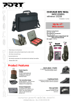
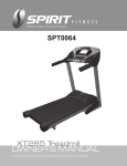
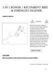
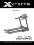
SB700-SOL0023
OWNER’S MANUAL
GROUP EXERCISE BIKE
Table of Contents
Important Safety Instructions……………………………………………………….…………3
Guidelines for Safe Operation…………………………………………………….…………..4
Hardware Assembly Pack……………………………………………………………………..5
Adjusting the Bike for a Proper Fit………………………………………………….………...10
Dual Function pedal……………………….………………………………..………….………11
Basic Operation / Maintenance Guidelines……………………………………….……..…..12
Parts list………………………………………………………………………………………….13
Exploded View Drawing..………………………………………………………………………16
SOL0023/SB700_Ver.A
2
IMPORTANT SAFETY INSTRUCTIONS
2.
READ ALL INSTRUCTIONS BEFORE USING THIS EXERCISE EQUIPMENT
Use this equipment only for its intended use as described in this manual. Do not attempt
to ride this bike at high pedal speeds until you have ridden the bike for some time and
are comfortable riding at slower pedal speeds.
The bike is NOT equipped with a freewheel system which means that when the flywheel
3.
is in motion, the pedals will be in motion. Do not attempt to stop the unit by applying
backward pressure to pedals while they are turning as knee injury may occur. Do not
attempt to remove your feet from pedals while they are moving.
Wait for flywheel to coast to a stop before dismounting the bike. If you want to stop the
1.
4.
5.
flywheel, push down on the brake knob.
Serious injury or death may occur from over-training. Consult a medical doctor or
qualified fitness instructor to determine an exercise program appropriate for your level
of fitness.
6.
Do not attempt to turn the pedal cranks by hand. Do not touch any driving mechanism
while it is in motion as possible injury could occur.
In a home setting, keep children away from the bike when it is not in use. Keep children
7.
8.
9.
and pets away from the unit while it is in use.
Do not attempt to perform dip movements on handlebars.
Never drop or insert any object into any opening of the bike.
Only use the bike on a stable, level floor.
10.
11.
Follow instructions for safe use of the equipment including proper seat position,
handlebar position, and use of foot positioning system of pedals. Do not attempt to pull
up handlebar post and seat post over the ‘MAX.’ graduation.
For safe operation, allow for at least 1foot (30cm) of free space to either side of the unit
and 2 feet (60cm) of free space to the rear of the unit.
Regularly examine the bike for damage and wear. Inoperable components should be replaced
immediately or the equipment should not be used until it is repaired.
Failure to follow all guidelines may compromise the effectiveness of the exercise experience,
expose yourself (and possibly others) to injury, and reduce the longevity of the equipment.
3
GUIDELINES FOR SAFE OPERATION
WARNING!
AS THE OWNER OF THIS EXERCISE EQUIPMENT, YOU SHOULD INSIST THAT ALL
USERS FOLLOW THE SAME GUIDELINES: YOU SHOULD MAKE THIS MANUAL
AVAILABLE TO ALL USERS.
1.
Obtain a complete physical examination from your medical doctor and enlist a
health/fitness professional’s aid in developing an exercise program suitable for your
current health status.
2.
When working out for the first time, start out slowly for a minimum of five minutes. After
your muscles are warmed up, gradually increase the pedaling rate zone.
The speed and duration of your exercise program should always be subject to how you
feel. Never permit peer pressure to exceed your personal judgment while exercising.
3.
4.
5.
Overweight or severely de-conditioned individuals should be particularly cautious when
using the equipment for the first time. Even though such individuals may not have
histories of serious physical problems, they may perceive the exercise to be far less
intense than it really is, resulting in the possibility of overexertion or injury.
Proper installation and regular maintenance are required to ensure user’s safety.
Maintenance is the sole responsibility of the owner.
4
Hardware Assembly Pack
#49. 5/16" × 1.5T_
Split Washer (4pcs)
#88. 5/16" × 5/8"_
Button Head Socket Bolt (4pcs)
#48. 5/16" × 16 × 1T_
Flat Washer (4pcs)
#91. M5 × 10m/m_
Phillips Head Screw (2pcs)
#82. 3/8"
Cap Nut (4pcs)
#83. 3/8" × 23 × 1.5T_
Curved Washer(4pcs)
#81.3/8" × 3-1/2"_
Carriage Bolt (4pcs)
#85.14/15m/m_Wrench(1pc)
#86. Combination 5mm Allen Wrench
& Phillips Head Screw Driver(1pc)
5
STEP 1
•
Stabilizer Assembly
Install the front and rear stabilizers with four 3/8"×3-1/2" carriage bolts (81), four 3/8" curved
washers(83) and four 3/8" cap nuts(82). The front and rear stabilizer are different. Be sure to
assemble the stabilizer with the wheels onto the front of the bike.
6
STEP 2
•
Rear Cover
Install the rear stabilizer cover with two M5 x 10mm screws (91).
7
STEP 3
Handlebar and Drink Holder
•
Install the handlebars with four 5/16" x 15mm bolts (88), 5/16" split washers (49) and four
5/16” flat washers (48). Tighten the bolts securely.
•
Install the drink holder to the handlebars by loosening the thumb screw, clamp to the
handlebars and re-tighten the thumb screw.
8
STEP 4
•
Pedal Assembly
Install the Left (25L) and Right (25R) pedals to the crank arms. Please note that the Left pedal
has a reverse threaded bolt and needs to be tightened in a counterclockwise direction. The
pedals are identified by either an R or L stamped into the end of the bolt.
Right Pedal
Left Pedal
9
ADJUSTING THE BIKE FOR A PROPER FIT
Take some time to learn how to properly adjust the bike to your body; it will make your workouts
more pleasant and a safer experience too. Riding the bike when it is incorrectly adjusted can result
in discomfort and increase your risk of injury.
Adjustment of Seat Position:
Seat Height Adjustment
1. Standing next to the bike, adjust seat until it is about hip height.
2. Rotate crank arms until the pedals are in the vertical position: 12 and 6
o’clock.
3. Place your foot in toe cage of pedal closest to the floor and mount the
bike. Ensure that the ball of your foot is over the center of pedal. Your leg
should be slightly bent at the knee, about 5 degrees.
4. If your leg is too straight or your foot cannot touch pedal you will need to
lower seat height. If your leg is bent too much you will need to raise seat
height.
5. Dismount the bike. Loosen the quick release lever on seat post and adjust up or down as
necessary.
6. When seat is in the desired position, tighten the quick release to secure the seat post.
7. Note the final position mark on the seat post for future reference.
Seat Forward/Aft Adjustment
1. Sit on bike with crank arms in the 3 and 9 o’clock positions. For road bike
training, a proper forward/aft position of the seat is achieved when small
bump at the top of the shin is above pedal axle.
2. Dismount the bike. Loosen the quick release under the seat and slide the
seat forward or backward as desired; then tighten the quick release.
Handlebar Adjustment:
Handlebar Height Adjustment
1. The Handlebar height is a matter of preference. Start with a handlebar height that is the same
as the seat’s height. Adjusting the handlebar higher will give the rider a more upright position;
lower will result in a more crouched position.
2. Raise or lower the handlebar by loosening quick release on handlebar
post and adjust by sliding the handlebar mount up or down as desired.
Then tighten the quick release to secure the handlebar post. Note the
final position mark on handlebar post for future reference.
Adjustment of Handlebar’s Forward/Aft Position
1. Loosen the quick release under the handlebar and slide the handlebar
forward or backward as desired. Suitable forward/aft position should allow the rider to
comfortably grasp the handlebar with a slight bend at the elbow.
2. Tighten the quick release to secure the handlebar assembly.
10
DUAL FUNCTION PEDAL
ADJUSTING THE PEDAL STRAPS
Place your feet in between the aluminum surface of the pedal and the nylon foot strap that
wraps around it. If the opening is too narrow, depress the spring loaded clasp with one hand
and pull on the nylon strap with the other to increase the opening area. If it is too loose or to
tighten the strap, depress the spring loaded clasp, then pull on the open end of the nylon
strap until the strap is snug around each foot.
11
BASIC OPERATION
Now that you have established a proper riding position, take a few minutes to ride the bike and
determine that your position is comfortable. Start pedaling at a slow pace with your toes and
knees pointed directly forward. Hold the handlebar lightly and in a position that allows your
shoulders and upper body to relax. Pedal easily, at a low resistance until you feel confident that
you could ride in that position for the duration of your workout.
WARNING!
IF AT ANY TIME DURING YOUR WORKOUT, YOU FEEL CHEST PAIN, EXPERIENCE SEVERE
MUSCULAR DISCOMFORT, FEEL FAINT, OR ARE SHORT OF BREATH, STOP EXERCISING AT
ONCE. IF THE CONDITION PERSISTS, YOU SHOULD CONSULT YOUR MEDICAL DOCTOR
IMMEDIATELY.
1.
2.
3.
Pedaling resistance is controlled by the tension knob. Resistance can be changed at any
time by turning tension knob: clock-wise for more resistance; counterclockwise for less
resistance.
To apply the brake, press down on the tension knob.
Before dismounting, apply the brake to stop flywheel, or increase resistance and let
flywheel come to a stop.
MAINTENANCE GUIDELINES
MAINTENANCE SCHEDULE
LUBRICANT
PART
RECOMMENDED ACTION
FREQUENCY
CLEANER
Pedals
Ensure that pedals are tight in Before each use
N/A
N/A
crank arms; that all screws on
pedals are tight; and that the
pedal straps are not frayed
Frame
Wipe down by using a soft
Daily
Water
N/A
damp clean cloth
Flywheel
Wipe down by spraying on a
Weekly
WD-40
N/A
rag and applying a light coat
spray.
to sides of the flywheel
Brake Pad Inspect for excessive wear or
Weekly
N/A
3-IN-ONE Oil or
a dry leather brake pad
10W oil. Do not
use silicone-based
lubricants
1. Do not service internal parts of pedals. If they are found to be worn internally, we recommend
replacing the pedal.
2. Use of lubricants or cleaning solutions other than those so specified will result in diminished
performance and a shorter life span for that part.
12
PARTS LIST
No.
Description
Qty
1
Main Frame
1
2
Front Stabilizer
1
3
Rear Stabilizer
1
4
Handlebar Post
1
5
Seat Post
1
6
Handlebar
1
7
Sliding Seat Mount
1
8
Sliding Handlebar Mount
1
9
Brake Pad Bracket
1
10
Brake Pad - Wool Felt
1
11
Bushing
1
12
Nut
1
14
Spring
2
15
M10 × P1.25 × 3T_Luck Nut
2
16
Brake Tension Knob
1
18
M6 × 15mm_Phillips Head Screw
4
19
8 × 40m/m_Quick Release lever
2
20
8 × 25m/m_Quick Release Lever
2
21
Aluminum Locking V-Blocks
4
22
5/16" × 35 × 3.0T_Flat Washer
1
25
Pedal Set
1
26
Anti-Rotation Washer
1
27
Seat
1
29
5 × 16m/m_Tapping Screw
2
30
3.5 × 12m/m_Sheet Metal Screw
3
31
Flywheel
1
32
Bearing Housing
2
33
Flywheel Axle
1
34
Woodruff Key
1
35
Flywheel Pulley
1
36
5/16" × 3/4"_Button Head Socket Bolt
1
37
5/16" × 20 × 3.0T_Flat Washer
1
38
5/16" × 3/4"_Button Head Socket Bolt
6
39
M6 × 10L_Flat Phillips Head Screw
6
40
Belt
1
41
Drive Pulley
1
42
Crank Arm
1
43
(25L.25R)
(L)
Crank Arm(R)
1
13
No.
Description
Qty
44
Crank Arm Dust Cap
2
45
Crank Axle
1
46
5/16" × 1/2"_Button Head Socket Bolt
5
48
5/16" × 16 × 1T_Flat Washer
4
49
5/16" × 1.5T_Split Washer
4
50
Transportation Wheel
2
53
Rubber Foot
4
54
3/8"_Nut
4
55
Stabilizer End Cap
4
56
End Cap, Eye Tube
2
57
Plastic Slide Insert, Eye Tube
2
58
Bottom End Cap, Eye Tube
2
59
Rear Stabilizer Cover
1
60
Chain Cover
1
61
(Outer)
Chain Cover(Inner)
62
Flywheel Fender
1
63
Pulley Cover
1
64
6004_Bearing (NSK)
2
65
6203_Bearing
2
66
6004_Bearing (TMT)
2
67
Ø17_C Ring
1
68
Ø20_C Ring
3
69
1/4" × 3"_Hex Head Bolt
1
70
1/4"_Hex Head Bolt
1
71
1/4" × 5.5T_Nyloc Nut
1
72
3/8" × 2"_Flat Head Socket Bolt
2
73
Ø16.7 × 2.5T_Star Washer
1
74
Idler Axle
1
75
Idler Adjustment Carriage Bolt
1
76
Console Assembly
1
77
Foam Stop, Handlebar Eye Tube
1
78
Ø5/16" × 23 × 2.0T_Flat Washer
1
79
3/8" × 19 × 1.5T_Flat Washer
2
80
M10 ×
P1.25_Nut
2
81
3/8" × 3-1/2"_Carriage Bolt
4
82
3/8"_Cap Nut
4
83
3/8" × 23 × 1.5T_Curved Washer
4
84
M5 × 12m/m_Tapping Screw
2
85
14/15m/m_Wrench
1
1
14
No.
Description
Qty
86
Combination M5 Allen Wrench & Phillips Head Screw Driver
1
87
Drink Bottle(Optional)
1
88
5/16" × 5/8"_Button Head Socket Bolt
4
89
M5 × 10m/m_Socket Head Cap Screw
2
90
Ø5 × 10m/m_Tapping Screw
4
91
M5 × 10m/m_Phillips Head Screw
2
92
M5_Speed Nut Clip
2
93
M5 × 10m/m_Tapping Screw
7
94
Spring
1
96
Safety Sleeve
1
97
5/16" × 1"_Button Head Socket Bolt
1
98
Sleeve Bushing
1
99
3/8" × 3/4"_Button Head Socket Bolt
2
100
3/8" × 21 × 2T_Flat Washer
2
15
Exploded View Drawing
16
WARRANTY, SAFETY AND ASSEMBLY INFORMATION
SOL0023- SPIN BIKE
IMPORTANT
Please read and retain this manual as it will assist with identification for parts and service.
-----------------------------------------------------------------------------------------------------------BOYLES FITNESS warrants their SPIN BIKE to be free from defects in material and workmanship
under normal use and service conditions.
The various components of the SPIN BIKE are warranted against defects and workmanship for the
time periods specified as follows:
SOL0023 –SPIN BIKE
LIMITED WARRANTY
Frame
Lifetime
Parts
2 years
All warranty coverage extends only to the original retail purchaser from the date of purchase.
BOYLES FITNESS’ obligation under this Warranty is limited to replacing or repairing, at BOYLES’
option, the product or parts therein. Any enquiries relating to warranties or spare parts must be
directed to our Service 07 3272 7010.
For efficient processing of your enquiry please have relevant date of purchase, retailer name you
purchased the item from and the brand on the product. This warranty does not extend to any
damage to a product caused by abuse, improper or abnormal usage (as detailed in this instruction
manual), or repairs not provided by BOYLES. Nor does this warranty extend to products used for
commercial or rental purposes. This warranty does not cover ordinary wear, tear and weathering,
failure to follow directions, improper installation, improper maintenance or acts of God (such as
damage caused by storms, lightning and by snow or ice). No other Warranty beyond that specifically
set forth above is authorised by BOYLES.
Our sales and service centre has been set up to provide assembly assistance, replacement parts
and accessories, and to efficiently handle all warranty related matters.
Phone
07 3272 7010
Hours
9:00am – 4:00pm Mon-Fri (excluding public holidays)
Email:
[email protected]
Website
www.bfe.net.au
17
BFE Warranty Policy – November 1st 2013
1. When purchased from an authorised BFE distributor the BFE warranty shall guarantee that all framework
and components of your product are free from faulty manufacture. All faulty framework and components will
be repaired or replaced as set out in this policy. All warranties in this policy apply to INDOOR
HOME/DOMESTIC USE ONLY.
2. These warranties do not apply to products used in commercial use applications.
3. Warranty DOES NOT cover normal wear & tear and excludes faults due to misuse, abuse, incorrect
assembly or lack of general maintenance.
4. Warranty is applicable to products sold and placed within Australia only.
5. IMPORTANT. Most of BFE products are pretested and we have inspectors checking all products prior to
shipment. The number one reason for a fault is due to INCORRECT ASSEMBLY.
If you do have problems please go back to the start and double check your assembly and pay special
attention to all WIRING connections. If you have accidently cut or damaged the wiring please let us know
and we will be happy to send you a new set at no-charge.
If you have done this and are confident you have double checked your assembly and are still having
problems please email our service department at [email protected] including your best
contact details ,proof of purchase, serial number and a brief explanation of what is wrong.
Emailing is the quickest and most reliable way to get your service request processed. Once we have your
details we will either call or email you back with the next steps. The quickest way, once we determine the
problem and send you a replacement part, is that we can talk you through over the phone on how to fit it.
If it is deemed by our service tech that it is too difficult, we can arrange (where available) a service
technician.
NOTE. If we arrange for a service technician ( where applicable) and it is found that it is not a
manufactures fault and found to be an assembly issue , normal wear and tear, transport damage or misuse
then there will be a call out fee of $140 depending on location. (Surcharge applies for non-metro areas)
WARRANTY TERMS- Warranty commences from the date of purchase from the retail store. Warranty only applies
to the original purchaser and is NON transferable. Warranty is void if the serial number of the product has been
removed or tampered with.
Warranty does not apply to defects, faults or failures due to:
(a) Defects caused during assembly or failure to assemble to the assembly manual provided. Assembly errors
include but are not limited to damaged wiring harness, stripped crank arms and or pedals and bolts used in
the wrong locations.
(b) Lack of general maintenance and or failure to service or maintain the equipment in accordance with the
user manual specifications and recommendations.
(c) Power Surges. The computers, control boards and motors are very sensitive to power fluctuations. You
must use a surge protector on all items that plug into your mains power otherwise your electronics will not
be covered by this warranty. You can purchase these from numerous retailers or you can call us on 02 46
366 680 to get a price.
(d) User negligence, abnormal or excessive use, misuse, abuse or transport damage.
(e) Repairs, alterations or modifications by NON BFE authorised service technician.
(f) Accident, fire, flood or malicious damage by third person.
(g) Ordinary wear and tear.
(h) Failure to keep the product in a clean, dry environment causing rust. You should wipe off any sweat and
moisture after each training session.
(i) Any products sold or placed in an application or the incorrect environment that is not recommended by BFE
or as not stipulated in the owner’s manual such as a commercial / rental environment will void the warranty
set forth by BFE
(j) BFE recommends the use of a protective rubber floor mat. This reduces the incidence of dust and lint
collection around the motor, reduces noise & protects your floor. You can purchase this from your retailer or
contact BFE directly at [email protected]
BFE will have the option to repair or replace any product which requires attention under the warranty.
NOTE: Lifetime refers to the warranty coverage of the units expected service life. NOT the lifetime of the
purchaser.
18
Servicing/Spare Parts- As with any mechanical equipment general maintenance should be performed on
a regular basis by an authorised retailer or service technician. This will ensure longevity of the product and
ensure that it is kept working in optimum condition. Failure to properly maintain your equipment may lead to
safety issues and may also void the warranty.
You should only use genuine BFE replacement parts otherwise the warranty will be void.
Freight Costs:
The cost of freighting the replacement part under warranty to the customer shall be free of charge. Your
requirement is to return the faulty part via the pre-paid postal service which we will supply.
Returned Goods:
The unauthorised return of parts or product shall be refused and placed in the hands of the carrier at the
cost of the shipper. Return authorisations can be obtained from BFE head office only.
Additional Warranty
If you would like to extend your labour warranty by 1 year ($99), 2 years ($199), 3 years ($299) please
contact our office by emailing [email protected] (Not available in all areas)
Service Department hours: Monday to Friday between 9am and 4pm
Service Phone Number: 07 3272 7010 Email: [email protected]
PLEASE NOTE: that Authorised service technicians do not reside in all areas of this vast country. If you live
beyond the reasonable service area of a metropolitan area, BFE may not be able to support the labour
portion of the product warranty. Alternatively you can return (at your cost) your product to the closest BFE
repair centre, where it will be fixed at no charge under the warranty period.
Metropolitan Area- defined as no more that 50km from G.P.O in all capital cities.
Disclaimer:
Our goods come with guarantees that cannot be excluded under the Australian Consumer Law. You are
entitled to a replacement or refund for a ‘Major failure’ and for compensation for any other Reasonable
foreseeable loss or damage.
You are also entitled to have goods repaired or replaced if the goods fail to be of an acceptable quality and
the failure does not amount to a major failure.
BFE does not assume , nor authorise any representative or other person to make or assume for BFE , any
warranties whatsoever, whether expressed or implied, in , in connection with the sale, service, or shipment
of our products.
BFE reserve the right to make changes and improvements in our products and specifications without
incurring any obligation to similarly alter products previously purchased.
This warranty operates in addition to other rights and remedies available to consumer’s rights under the
Australian Consumer Law.
Service Department hours: Monday to Friday between 9am and 4pm
Service Phone Number: 07 3272 7010 Email: [email protected]
19