1
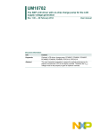
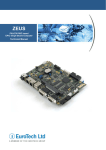
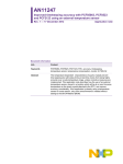
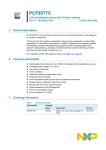
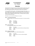
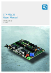
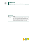
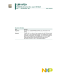
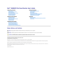
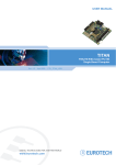
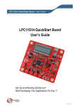
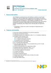
UM10300 User Manual OM6290 LCD Demo Board Rev.1.0 — 8 August 2008 User manual Document information Info Content Keywords LCD driver, segment driver, character driver, graphic driver, PCF8576D, PCF2119, PCF8531, PCA9633, ARM7, LPC2148, battery powered, USB Abstract The OM6290 is a LCD driver evaluation board which can be used to demonstrate and evaluate three different types of LCD drivers: The PCF8576D is a segment driver, the PCF2119 a character driver and the PCF8531 a dot matrix driver. The NXP family of LCD drivers consists of these three different types, with several type numbers for each type. From an application point of view, the type numbers within one type family are very similar and also software can be easily adapted. The board provides a starting point for applications using an NXP LCD driver, both from the hardware and software point of view. UM10300 NXP Semiconductors User Manual OM6290 Revision history Rev Date Description 01 20080808 Initial version Contact information For additional information, please visit: http://www.nxp.com For sales office addresses, please send an email to: [email protected] UM10300_1 User manual © NXP B.V. 2008. All rights reserved. Rev 1.0 — 8 August 2008 2 of 30 UM10300 NXP Semiconductors User Manual OM6290 1. Introduction This User Manual describes the OM6290 LCD Demo board. This board was developed in order to provide a tool for application engineers and development engineers wishing to try and evaluate the possibilities of some of our LCD driver IC’s and to get hands-on experience with writing code for these drivers. Code written using this board can be used in the final application which enables rapid prototyping. The board can also serve as an example for the hardware related aspects of a design using NXP LCD drivers. Features: Demonstrates how to use NXP LCD drivers Contains three displays controlled by I2C LCD drivers: • Segment display driven by segment driver PCF8576DT, TSSOP56 • Character display with character driver PCF2119S (COG, Chip On Glass) • 128 * 34 dot matrix display with graphic driver PCF8531 (COG) PCA9633 I2C bus controlled LED driver for back light ARM7 based NXP microcontroller LPC2148 with 512 KB flash memory User modifiable firmware, In-System/In-Application Programming (ISP/IAP) via UART USB2.0 compliant interface JTAG interface I2C interface Unused pins of microcontroller available on pin strip Power supply using 9V battery (stand alone) or via USB Box contents: • OM6290 LCD driver evaluation board • USB2.0 cable • 9V battery The three drivers all include an I2C interface and can be programmed via the onboard NXP micro controller LPC2148 which is built around an ARM7 core. The PCF8576D is a Segment Driver and has a lot in common with other NXP Segment Drivers such as PCF8532 (4 x 160 segments), PCF8533 (4 x 80), PCF8534A (4 x 60), PCF8562 (4 x 32) and PCF8566 (4 x 24). The PCF2119 is a Character Driver and has a lot in common with other members of the family like PCF2113 and PCF2116. The PCF8531 is a Graphic Driver (Row/Column) and the NXP family of Graphic Drivers contains some other types like PCF8535. Experiences gained with the onboard drivers can easily be used for working with the other drivers belonging to the same family. The 12nc of the OM6290 board is 9352 861 74598. UM10300_1 User manual © NXP B.V. 2008. All rights reserved. Rev. 1.0— 8 August 2008 3 of 30 UM10300 NXP Semiconductors User Manual OM6290 2. Board description and layout Below the top view of the board is given. LCD3 is the large display on the left. For this display a backlight is used which is controlled by the PCA9633 LED driver. On the top right LCD2 is present and the smaller display below LCD2 is LCD1. Fig 1. Top view of LCD Demoboard UM10300_1 User manual © NXP B.V. 2008. All rights reserved. Rev. 1.0— 8 August 2008 4 of 30 UM10300 NXP Semiconductors User Manual OM6290 For best optical performance, remove the protective foils from the three displays. In order for the board to work standalone, jumpers J1 and J2 (I2C) must be placed as well as jumper J4. Default position for J4 is ‘Enabled’, enabling LED driver PCA9633 (IC5). 2.1 Switches Three switches are present next to the large display LCD3. SW1 is used to select the predefined patterns/text present in the firmware for display on LCD1. SW2 has the same function but then for LCD2 and SW3 selects the pattern that will be displayed on LCD3. Furthermore SW3 can be used to select some lighting modes of backlight BL1 which is mounted under LCD3. SW4 is located near the bottom of the board and is the reset switch. At start up all displays will display some text and when SW1 or SW2 or SW3 is pressed, the displayed text/pattern on the related display will change. Switch S1 can be used to select “Program Internal Flash” of the LPC2148 in order to program modified firmware, or to let the LPC2148 boot from its internal flash. The OM6290 is a USB-powered device. Alternatively the board can be powered using a standard 9V (6LR61 / PP3) battery. A battery holder is present on the board and switch S2, located between the battery holder and LCD3, can be used to select either USBpower or battery power. 2.2 LED indicators The board contains two LED indicators. LED D7 (green) indicates that +5V is present on the board, supplied either via USB or via the +9V battery. The +3V3 is derived from +5V. LED D4 (orange/red, labeled LINK) is on when firmware has been loaded into the flash memory. If S1 is in position “Program Flash” and the board is reset, D4 goes off and the board is ready to be flashed. After programming the board, move S1 to “Boot from Flash” and reset the board by pressing SW4 “RESET”. D4 will turn on now. 2.3 Jumpers The board contains five jumpers. • J1 (SDA) and J2 (SCL), positioned just below the micro controller, allow disconnecting the I2C bus on the board from the LPC2148 I2C interface. When jumpers J1 and J2 are lifted, the I2C connections to the micro controller are disconnected and the display drivers can be programmed via any other micro controller or application with I2C-interface. The I2C signals SDA and SCL as well as GND and 3V3 and 5V are available on the pin strip P3 just above the 9V battery. • J3, near the bottom of the board, can usually be left open. If present it allows resetting the microcontroller via serial interface RS1, required for ISP programming. • J4 is used to enable/disable the outputs of the PCA9633 LED driver which is used for backlight BL1. Default position is enabled. If it is put in position ‘uCONTR’ it is possible to use the firmware to disable and enable the outputs. • J5 is used to enable the JTAG interface. In this case also connector P4 must be mounted on the board. This would be useful to explore the LPC2148 more indepth. UM10300_1 User manual © NXP B.V. 2008. All rights reserved. Rev. 1.0— 8 August 2008 5 of 30 UM10300 NXP Semiconductors User Manual OM6290 2.4 Connectors On the left below LCD3 a pin strip P3 is available which carries the following signals: 5V, 3V3, SCL, GND, SDA and nRES. The latter is connected to the reset circuit IC6 and by making nRES LOW, a defined reset signal is generated. On the right side of the board a USB connector has been provided. At the time of writing the first revision of this manual the only purpose of the USB connector is to offer the option of powering the board via USB. Future updates of the firmware which would also enable data communication between the LCD driver ICs and a GUI which then would run on a PC, are under consideration. The serial interface RS1 (UART) below the USB connector is used for updating the firmware in the microcontroller. 2.5 Reserved components The board layout includes a few components which are not directly necessary for the primary purpose of the board which is providing a hands-on tool to work with the three different types of NXP LCD drivers. Therefore these components are not mounted. However, in some scenario’s it may be desired to explore more of the options of the onboard microcontroller. Therefore three optional areas may be mounted by the user of the board in order to add extra functionality. 1. Real Time Clock of LPC2148: By mounting a 32.768 kHz crystal at position Y2 as well as two capacitors at positions C29, C30 the internal RTC can be used. The values of C29 and C30 depend on the crystal used. A crystal for an RTC is designed to operate with a certain load capacitance CL. A common value for the required load capacitance of such a crystal is 12.5 pF. Seen from the crystal C29 and C30 are in series. Taking into account parasitic capacitances as well, C29 and C30 will have to be 22 pF or 25 pF if a 12.5 pF crystal is used. 2. JTAG interface: On the right side of the board under LCD1, space is provided for a JTAG connector. This is a 20-pin header with pitch of 2.54 mm. The required pull-up resistors are already mounted. 3. Pin strips P1 and P2 near the bottom edge of the board. If a pin strip is soldered on the board at this position, all unused pins of the microcontroller are accessible. If mounted, exercise caution not to overload these signal lines ! Besides these microcontroller related items, another option is to remove resistor R29 (470 Ω) and mount potentiometer Pot1 (4k7) instead. This enables adjustment of the contrast of display LCD3. The location of these components is between LCD2 and LCD3. UM10300_1 User manual © NXP B.V. 2008. All rights reserved. Rev. 1.0— 8 August 2008 6 of 30 UM10300 NXP Semiconductors User Manual OM6290 2.6 Hardware requirements In order to be able to modify the firmware of the OM6290 Demo Board you need: • The OM6290 Demo Board • An IBM-compatible PC with an unused USB port to supply power to the board (alternatively via a battery) and an unused RS232 COM port for Flash In-System Programming (ISP) via the Serial Interface. • 70 Megabytes free hard disk space (depending on the IDE used) • 128 Megabytes of RAM • A serial cable, 9-pin male to 9-pin female, no longer than 10ft/3m, wired one-to-one, in order to program new firmware on the OM6290 board, using the FlashMagic tool, see below. 2.7 Software requirements In order to be able to modify or write code the following software is required: • Windows Operating System (Windows 2000, Windows XP or Windows Vista); • A development tool for ARM7 cores providing source code editing, compiling, linking and debugging. A good (free) option is the evaluation version of the Keil Microcontroller Development Kit (MDK-ARM). At the time of writing the latest is mdk322a, which is Version 3.22 (or use later versions as they become available). This can be downloaded at https://www.keil.com/demo/eval/arm.htm (registration required). The RealView MDK includes μVision (Integrated Development Environment, Debugger and Simulator) and RealView compilation tools for C/C++ and linker. For more information see http://www.keil.com/arm; • Programming utility FlashMagic to flash the .hex file into the LPC2148, see http://www.flashmagictool.com/. This is freeware. For more information about how to use these tools refer to chapter 5. 2.8 Modes of operation The board can be used in two different modes: 1. stand-alone mode; after power-up pre-defined patterns/texts are displayed on the three displays. Using switches SW1, SW2 and SW3 it is possible to select various patterns. The firmware can be modified using the appropriate tools; 2. I2C remote mode; jumpers on the board (J1 and J2) can be removed such that the on-board microcontroller’s I2C bus is no longer connected to the display drivers. Via pin strip P3 all display drivers can be accessed directly from an external I2C-bus. This allows to access the display drivers on the board from any other application via I2C using a microcontroller residing on a separate board. Note: the following describes the operation of the version 1 software. Please refer to the Quick Start Guide that corresponds to your version of software for operating details. When the board is used in stand-alone mode (Software version 1.10) it behaves as follows. After power on, LCD3 is dark, the back light is off. LCD2 shows a welcome message and after a few seconds shows the message “Please press SW1, 2 or 3”. With early versions LCD1 shows the NXP logo at startup. Starting from firmware version v1.1 UM10300_1 User manual © NXP B.V. 2008. All rights reserved. Rev. 1.0— 8 August 2008 7 of 30 UM10300 NXP Semiconductors User Manual OM6290 LCD1 shows three lines of text, with in the right bottom corner the version number. Upon pressing any of the switches SW1, SW2 or SW3 the backlight of LCD3 turns on. LCD1. Power on: The NXP logo is displayed. Starting from v1.1, the following text is displayed over three lines,: “NXP founded by Philips” “For the latest updates” “visit www.nxp.com” When pressing SW1 the displayed pattern changes to the NXP logo and subsequent operation of SW1 results in alternating between the NXP logo, displaying the type number of the driver (PCF8531) and displaying a face. LCD2. At power on the message “ * welcome * ” enters the upper line, shifting from right to left. This shows the ‘display shift’ feature. After that the message “Please press SW1, 2 or 3” appears. When SW2 is pressed, the display shows “NXP Insightful”. Pressing once more results in “NXP Inventive”. Consecutive pressing of SW2 results in cycling through texts “NXP Engaging”, “NXP Excellence”, “USE SW3 FOR BACKLIGHT” and “NXP PCF2119s”. Hereafter the cycle starts again. When the message “USE SW3 FOR BACKLIGHT” is displayed, SW3 does not control what is being displayed on LCD3, but instead changes the backlight colour and/or intensity when pressed. Also note that only when this message is displayed, a cursor is seen blinking on the right of the message. This demonstrates the feature ‘cursor blink’ of the PCF2119. LCD3. Power on: The display is blank, then after a few seconds the counter read “000”. Pressing SW1 – SW3 increments the count. Pressing SW3 once results in the text “CH” being displayed. Operating SW3 a 2nd time results in all segments being lit up. When now SW3 is pressed a 3rd time, it restarts the cycle with a blank display again. 3. The LCD Drivers The board contains three different types of LCD drivers. This chapter describes the used drivers on the board. The key values of NXP LCD drivers are listed below. Segment drivers: • High segment count, leading in number of segments supported per single device; 60 x 4, 80 x 4, 160 x 4; • AEC-Q100 automotive qualification. Character drivers: • Separate icon row for versatile usage. Graphic drivers (dot matrix): UM10300_1 User manual © NXP B.V. 2008. All rights reserved. Rev. 1.0— 8 August 2008 8 of 30 UM10300 NXP Semiconductors User Manual OM6290 • Resolutions that are not common in the market: 34 x 128, 65 x 133, 80 x 128. 3.1 Segment Driver PCF8576D 3.1.1 General Description The PCF8576D is a peripheral device which interfaces to almost any Liquid Crystal Display (LCD) with low multiplex rates. It generates the drive signals for any static or multiplexed LCD containing up to four backplanes and up to 40 segments. It can be easily cascaded for larger LCD applications. The PCF8576D is compatible with most microprocessors / microcontrollers and communicates via a two-line bidirectional I2Cbus. Communication overheads are minimized by a display RAM with auto-incremented addressing, by hardware sub-addressing and by display memory switching (static and duplex drive modes). It has a lot in common with other NXP Segment Drivers such as PCF8532 (4 x 160 segments), PCF8533 (4 x 80 segments), PCF8534A (4 x 60), PCF8562 (4 x 32) and PCF8566 (4 x 24). 3.1.2 Features single chip LCD controller / driver selectable backplane drive configuration: static or 2 / 3 / 4 backplane multiplexing selectable display bias configuration: static, 1/2 or 1/3 internal LCD bias generation with voltage-follower buffers 40 segment drives: • up to twenty 8-segment numeric characters • up to ten 15-segment alphanumeric characters • any graphics of up to 160 elements 40 x 4-bit RAM for display data storage auto-incremented display data loading across device subaddress boundaries display memory bank switching in static and duplex drive modes versatile blinking modes independent supplies possible for LCD and logic voltages wide power supply range: from 1.8 to 5.5 V wide logic LCD supply range: from 2.5 V for low-threshold LCDs up to 6.5 V for guest-host LCDs and high-threshold (automobile) TN LCDs low power consumption 400 kHz I2C-bus interface compatible with 4, 8 or 16-bit microprocessors or microcontrollers may be cascaded for large LCD applications (up to 2560 elements possible) no external components compatible with chip-on-glass and chip-on-board technology UM10300_1 User manual © NXP B.V. 2008. All rights reserved. Rev. 1.0— 8 August 2008 9 of 30 UM10300 NXP Semiconductors User Manual OM6290 manufactured in silicon gate CMOS process AEC-Q100 compliant (TQFP64). 3.1.3 Block diagram S0 to S39 BP0 BP2 BP1 BP3 56 VLCD 55 1 2 BACKPLANE OUTPUTS 4 to 43 3 DISPLAY SEGMENT OUTPUTS DISPLAY REGISTER LCD VOLTAGE SELECTOR VSS CLK SYNC OSC VDD SCL SDA 54 OUTPUT BANK SELECT AND BLINK CONTROL DISPLAY CONTROLLER LCD BIAS GENERATOR PCF8576DT 47 CLOCK SELECT 46 AND TIMING BLINKER TIMEBASE 49 POWER-ON RESET OSCILLATOR COMMAND DECODER DISPLAY RAM 40 × 4-BIT WRITE DATA CONTROL DATA POINTER AND AUTO INCREMENT 48 45 44 I2C-BUS CONTROLLER INPUT FILTERS SUBADDRESS COUNTER 50 53 SA0 A0 A1 51 52 A2 001aab131 Fig 2. Block diagram of PCF8576D 3.2 Character Driver PCF2119 3.2.1 General Description The PCF2119x is a low power CMOS LCD controller and driver, designed to drive a dot matrix LCD display of 2-line by 16 or 1-line by 32 characters with 5 x 8 dot format. All necessary functions for the display are provided in a single chip, including on-chip temperature compensated generation of LCD bias voltages, resulting in a minimum of external components and lower system current consumption. The PCF2119x interfaces to most microcontrollers via a 4 or 8-bit bus or via the 2-wire I2C-bus. The chip contains a character generator and displays alphanumeric and kana (Japanese) characters. The letter ‘x’ in PCF2119x characterizes the built-in character set. Various character sets can be manufactured on request. The character set of the PCF2119 on the demo board is ‘S’. A similar device is the PCF2113 (2-line by 12 or 1-line by 24 characters + 120 icons). UM10300_1 User manual © NXP B.V. 2008. All rights reserved. Rev. 1.0— 8 August 2008 10 of 30 UM10300 NXP Semiconductors User Manual OM6290 3.2.2 Features Single-chip LCD controller/driver 2-line display of up to 16 characters + 160 icons, or 1-line display of up to 32 characters + 160 icons 5 x 7 character format plus cursor; 5 x 8 for kana (Japanese) and user defined symbols Icon mode: reduced current consumption while displaying icons only Icon blink function On-chip: • Configurable (4 times, 3 times or 2 times) voltage multiplier generating LCD supply voltage, independent of VDD, programmable by instruction; Using an external supply is also possible • Programmable temperature compensation of on-chip generated VLCD; range: −0.16 to −0.24 %/K • Generation of intermediate LCD bias voltages • Oscillator requires no external components but using an external clock is also possible Display Data RAM: 80 characters Character Generator ROM: 240, 5 x 8 characters Character Generator RAM: 16, 5 x 8 characters; 4 characters used to drive 160 icons, 8 characters used if icon blink feature is used in application 4 or 8-bit parallel bus and 2-wire I2C-bus interface CMOS compatible 18 row and 80 column outputs Three multiplex rates; 1 : 18 (for normal operation), 1 : 9 (for single line operation) and 1 : 2 (for icon only mode) Uses common 11 code instruction set (extended) Logic supply voltage range, VDD1 − VSS = 1.5 to 5.5 V (chip may be driven with two battery cells) Display supply voltage range, VLCD − VSS = 2.2 to 6.5 V HVgen supply voltage range, VDD2 − VSS = 2.2 to 4 V and VDD3 − VSS = 2.2 to 4 V Direct mode to save current consumption for icon mode and Mux 1 : 9 (depending on VDD2 value and LCD liquid properties) Very low current consumption (20 to 200 μA): • Icon mode: <25 μA • Power-down mode: <2 μA. UM10300_1 User manual © NXP B.V. 2008. All rights reserved. Rev. 1.0— 8 August 2008 11 of 30 UM10300 NXP Semiconductors User Manual OM6290 3.2.3 Block diagram C1 to C80 R17DUP 60 to 99, 101 to 140 R1 to R18 51 to 59, 141 to 149 100 18 80 VLCD1 44 to 49 COLUMN DRIVERS BIAS VOLTAGE GENERATOR ROW DRIVERS 80 18 DATA LATCHES VLCD2 VLCDSENSE 37 to 43 80 VLCD GENERATOR 36 SHIFT REGISTER 18-BIT SHIFT REGISTER 5 × 12 BIT 5 OSCILLATOR 168 OSC CURSOR AND DATA CONTROL VDD1 VDD2 VDD3 5 1 to 6 7 to 14 VSS1 22 to 29 VSS2 30 to 35 T1 T2 T3 CHARACTER GENERATOR RAM (128 × 5) (CGRAM) 16 CHARACTERS 15 to 18 CHARACTER GENERATOR ROM (CGROM) 240 CHARACTERS TIMING GENERATOR 8 20 DISPLAY DATA RAM (DDRAM) 80 CHARACTERS/BYTES 7 21 155 PD 153 7 7 DISPLAY ADDRESS COUNTER ADDRESS COUNTER (AC) 7 7 INSTRUCTION DECODER 8 DATA REGISTER (DR) INSTRUCTION REGISTER BUSY FLAG 8 PCF2119x 154 8 POR 163 DB3/SA0 I/O BUFFER 160 to 162 164 to 167 DB4 to DB7 DB0 to DB2 19 E 158 R/W 159 RS 151, 152 SCL 156, 157 SDA mgw571 Fig 3. Block diagram PCF2119x 3.3 Graphic Driver PCF8531 3.3.1 General Description The PCF8531 is a low power CMOS LCD row/column driver, designed to drive dot matrix graphic displays (32 rows x 128 columns) at multiplex rates of 1:17, 1:26 and 1:34. Furthermore, it can drive up to 128 icons. All necessary functions for the display are provided in a single chip, including on-chip generation of VLCD and the LCD bias UM10300_1 User manual © NXP B.V. 2008. All rights reserved. Rev. 1.0— 8 August 2008 12 of 30 UM10300 NXP Semiconductors User Manual OM6290 voltages, resulting in a minimum of external components and low power consumption. The PCF8531 is compatible with most microcontrollers and communicates via a two-line bidirectional bus (I2C-bus). All inputs are CMOS compatible. Similar devices are PCF8535 (65 rows x 133 columns) and PCF8811 (80 rows x 128 columns). Remark: The icon mode is used to reduce current consumption. When only icons are displayed, a much lower operating voltage (VLCD) can be used and the switching frequency of the LCD outputs is reduced. In most applications it is possible to use VDD as VLCD. 3.3.2 Features Single-chip LCD controller/driver 34 row and 128 column outputs Display data RAM 34 ⋅ 128 bits 128 icons (last row is used for icons) Fast mode I2C-bus interface (400 kbit/s) Software selectable multiplex rates: 1:17, 1:26 and 1:34 Icon mode with Mux rate 1:2: • Featuring reduced current consumption while displaying icons only On-chip: • Generation of VLCD (external supply also possible) • Selectable linear temperature compensation • Oscillator requires no external components (external clock also possible) • Generation of intermediate LCD bias voltages • Power-on reset. No external components required Software selectable bias configuration Logic supply voltage range VDD1 to VSS1 is 1.8 to 5.5 V Supply voltage range for on-chip voltage generator VDD2 and VDD3 to VSS1 to VSS2 is 2.5 to 4.5 V Display supply voltage range VLCD to VSS • Normal mode 4 to 9 V • Icon mode 3 to 9 V Low power consumption, suitable for battery operated systems CMOS compatible inputs Manufactured in silicon gate CMOS process. UM10300_1 User manual © NXP B.V. 2008. All rights reserved. Rev. 1.0— 8 August 2008 13 of 30 UM10300 NXP Semiconductors User Manual OM6290 3.3.3 Block diagram 34 VSS1 VDD2 VDD3 128 ROW DRIVERS VSS2 VDD1 C0 to C127 R0 to R33 COLUMN DRIVERS POWER-ON RESET ENR INTERNAL RESET RES T1 T2 PCF8531 T3 T4 DATA LATCHES VLCDIN BIAS VOLTAGE GENERATOR OSCILLATOR OSC MATRIX LATCHES TIMING GENERATOR VLCDSENSE VLCDOUT DISPLAY DATA RAM VLCD GENERATOR SCL SDA SDACK INPUT FILTERS MATRIX DATA RAM I2C-BUS CONTROL COMMAND DECODER DISPLAY ADDRESS COUNTER ADDRESS COUNTER mgs465 SA0 Fig 4. Block diagram PCF8531 4. The onboard microcontroller The microcontroller chosen for this board is the LPC2148 which is a member of the NXP ARM7 controller family. This microcontroller is based on a 16-bit/32-bit ARM7TDMI-S CPU with real-time emulation and embedded trace support and embedded high-speed flash memory of 512 kB. A 128-bit wide memory interface and a unique accelerator architecture enable 32-bit code execution at the maximum clock rate. For critical code size applications, the alternative 16-bit Thumb mode reduces code by more than 30 % with minimal performance penalty. The LPC2148 is highly over specified for the demo application program. This allows the user to program the MCU with much more advanced applications. Also, it has some very convenient features like an integrated USB interface and the possibility to program new firmware versions in the embedded flash using In-circuit Serial Programming via the PC’s serial port. This enables modifications in the firmware to be quickly evaluated. UM10300_1 User manual © NXP B.V. 2008. All rights reserved. Rev. 1.0— 8 August 2008 14 of 30 UM10300 NXP Semiconductors User Manual OM6290 Features include: 60-MHz, 32-bit ARM7TDMI-S with AHB/APB interfaces 512 KB of ISP/IAP Flash 40 KB of SRAM Very fast Flash programming via on-chip boot loader USB 2.0 full-speed (12 Mbps) device Two 10-bit A/D converters, providing 14 analog inputs 10-bit D/A converter Multiple serial interfaces: two I2C, two UARTs, one SPI, and one SSP Two 32-bit timers Real-time clock and Watchdog timer 45 Fast I/O pins (5-V tolerant) with up to 15-MHz switching rate Single 3.3-V supply LQFP64 package (10 x 10 x 1.4 mm) 5. Using µVision and FlashMagic In order to be able to modify or write code the following software is required: • Windows Operating System (Windows 2000, Windows XP or Windows Vista); • A development tool for ARM7 cores providing source code editing, compiling, linking and debugging. A good (free) option is the evaluation version of the Keil RealView MDK-ARM Microcontroller Development Kit. At the time of writing the first release of this manual, the latest is mdk322a, which is Version 3.22. This can be downloaded at https://www.keil.com/demo/eval/arm.htm (registration required). The RealView MDK includes μVision (Integrated Development Environment, Debugger and Simulator) and RealView compilation tools for C/C++ and linker. For more information see http://www.keil.com/arm; • Programming utility FlashMagic to flash the .hex file into the LPC2148, see http://www.flashmagictool.com. FlashMagic is freeware. 5.1 Keil µVision Evaluation Software from Keil has very few limitations. Each evaluation tool set includes the assembler, compiler, linker, debugger, and IDE. These tools allow to evaluate the quality of the generated code, the speed and flexibility of the debugger, and the ease-ofuse provided by the µVision IDE. Keil ARM Evaluation Kits are code size-limited and have the following restrictions: • The Evaluation Version of the µVision IDE/Debugger may not be used to create commercial products; • Programs that generate more than 16K Bytes of code and data will not compile, assemble, or link; • The evaluation tools create Symbolic Output Format when the RealView compiler is selected. Fully licensed tools generate standard ELF/DWARF files; • The debugger supports programs that are 16K Bytes or smaller; UM10300_1 User manual © NXP B.V. 2008. All rights reserved. Rev. 1.0— 8 August 2008 15 of 30 UM10300 NXP Semiconductors User Manual OM6290 • The RealView Linker does not accept scatter-loading description files for sophisticated memory layouts; • The RealView Linker restricts the base address for code/constants to 0xXX000000, 0xXX800000, or 0x00080000 where XX is 00, 01, ..., FF. This allows memory start addresses like 0x00000000 and 0x12800000; • It is not possible to generate position independent code or data; • The RealView C/C++ Compiler does not generate a listing file; • The CARM compiler, assembler, and linker (only available in older versions of the Keil MDK) are limited to 16K Bytes of object code. Source code may be of any size; • The GNU ARM tools (compiler, assembler, and so on) that are provided are not limited or restricted in any way. In Fig 5 a screenshot of the KEIL IDE is shown while the current firmware was being modified. For a full overview of available support tools (IDE) visit the NXP website. Fig 5. Screen shot of Keil μVision3 and firmware UM10300_1 User manual © NXP B.V. 2008. All rights reserved. Rev. 1.0— 8 August 2008 16 of 30 UM10300 NXP Semiconductors User Manual OM6290 5.1.1 Installing μVision An evaluation version of μVision can be downloaded from the Keil website. Registration is required. The latest version at the time of writing the first version of this manual was 3.22. The file name is mdk322a.exe. File size is close to 100 MB. After download has completed, double click the executable and follow the instructions. 5.1.2 Keil μVision Quick Start The kit firmware includes all the source code for the demo that is programmed into the on board LPC2148 when shipped. The demo project can be modified and downloaded to the board. Run μVision and under the menu item “Project” select “Open Project”. Edit the source code and again, under the “Project” menu item, select “Build Target of Build All Targets”. To download the code to the board, follow the instruction for Flash Magic in section 5.2. To create a new project to run on the LCD Eval Board, select The IDE has to be configured for the microcontroller used on the OM6290 board. In order to do so, select “Project” -> “New μVision Project” and enter a project name, after which a window similar to that indicated in Fig 6 pops up. Select LPC2148. Fig 6. Selecting the microcontroller UM10300_1 User manual © NXP B.V. 2008. All rights reserved. Rev. 1.0— 8 August 2008 17 of 30 UM10300 NXP Semiconductors User Manual OM6290 As the crystal used on the board is a 12MHz crystal, the setting in the IDE has to correspond with that. In order to achieve this, select Project -> Options for Target ‘OM6290’. The window below pops up. Set the Xtal frequency to 12 MHz. The ARM7 CPU is capable of executing two instruction sets; the ARM instruction set which is 32 bits wide or the Thumb instruction set which is 16 bits wide. This is a compressed form of the ARM instruction set. Although the Thumb instructions will result in lower code performance compared to ARM instructions, they will achieve a much higher code density. High performance (speed) is not needed here and thus ThumbMode is used. This can be selected under ‘Code Generation’, see Fig 7 below. For this, select the tab ‘Target’. Fig 7. Setting of some options One restriction of the evaluation version of μVision is that the RealView Linker restricts the base address for code/constants to 0xXX000000, 0xXX800000 or 0x00080000 where XX is 00, 01, … , FF. This allows memory start addresses like 0x00000000 and 0x12800000. Therefore the R/O Base needs to be set to 0 as indicated in Fig 8 for the code to compile. Select tab ‘Linker’. This is valid if the RealView compiler is selected as described below in 5.1.3 “Selection of the toolset”. The meaning of R/O and R/W is as follows: UM10300_1 User manual © NXP B.V. 2008. All rights reserved. Rev. 1.0— 8 August 2008 18 of 30 UM10300 NXP Semiconductors User Manual OM6290 • R/O: Read Only. This is code and constants. • R/W: Read and Write. This is data. Fig 8. Linker options 5.1.3 Selection of the toolset The downloaded demoboard firmware contains the file ‘OM6290 Demoboard.Uv2’ which is the project configuration file. All settings are correct. In case settings are made manually the information provided here is useful. μVision uses either the ARM RealView compilation tools, the ARM ADS compiler, the GNU GCC compiler or the Keil CARM compiler. Older versions of the Keil uVision IDE came with the CARM compiler and the GNU GCC compiler. After Keil became an ARM company, the CARM compiler was replaced by RealView and current downloads don’t include the CARM compiler anymore. It is recommended to use the RealView compiler since this is also the tool used by NXP for the development of the code for this board. In this case downloaded software will be compatible with the tool and time consuming fixes and adaptations are avoided. UM10300_1 User manual © NXP B.V. 2008. All rights reserved. Rev. 1.0— 8 August 2008 19 of 30 UM10300 NXP Semiconductors User Manual OM6290 The toolset to be used can be selected in the μVision IDE under Project -> Manage -> Components, Environment, Books. This is indicated in Fig 9. Fig 9. Selection of tool set 5.2 The FlashMagic Utility NXP has partnered with Embedded Systems Academy to provide a free tool for flash programming called FlashMagic. It uses a serial protocol and allows programming while the controller is in the target hardware and supports the entire LPC2000 family (except LPC288x). Most important features: • Straightforward and intuitive user interface; • Five simple steps to erasing and programming a device and setting any options desired; • Programs Intel Hex Files; • Automatic verifying after programming; • Fills unused Flash to increase firmware security; • Ability to automatically program checksums. Using the supplied checksum calculation routine the firmware can easily verify the integrity of a Flash block, ensuring no unauthorized or corrupted code can ever be executed; UM10300_1 User manual © NXP B.V. 2008. All rights reserved. Rev. 1.0— 8 August 2008 20 of 30 UM10300 NXP Semiconductors User Manual OM6290 • Program security bits; • Check which Flash blocks are blank or in use with the ability to easily erase all blocks in use; • Read the device signature; • Read any section of Flash and save as an Intel Hex File; • Reprogram the Boot Vector and Status Byte with the help of confirmation features that prevent accidentally programming incorrect values; • Display the contents of Flash in ASCII and Hexadecimal formats; • Single-click access to the manual, Flash Magic home page and NXP Microcontrollers home page; • Ability to use high-speed serial communications on devices that support it. Flash Magic calculates the highest baudrate that both the device and the PC can use and switches to that baudrate transparently; • Command Line interface allowing Flash Magic to be used in IDEs and Batch Files; • Manual in PDF format; • Supports half-duplex communications; • Verify Hex Files previously programmed; • Save and open settings; • Able to reset Rx2 and 66x devices (revision G or higher); • Able to control the DTR and RTS RS232 signals when connected to RST and /PSEN to place the device into BootROM and Execute modes automatically. An example circuit diagram is included in the Manual. Essential for ISP with target hardware that is hard to access; • Able to send commands to place the device in BootROM mode, with support for command line interfaces. The installation includes an example project for the Keil and Raisonance 8051 compilers that show how to build support for this feature into applications; • Able to play any Wave file when finished programming; • Built in automated version checker - helps ensure that always the latest version is used; • Powerful, flexible Just In Time Code feature. Write your own JIT Modules to generate last minute code for programming. Uses include: − Serial number generation − Copy protection and copy authorization − Storing program date and time - manufacture date − Storing program operator and location − Lookup table generation − Language tables or language selection − Centralized record keeping • Displays information about the selected Hex File, including the creation and modification dates, flash memory used, percentage of the current device used • For more information visit www.flashmagictool.com UM10300_1 User manual © NXP B.V. 2008. All rights reserved. Rev. 1.0— 8 August 2008 21 of 30 UM10300 NXP Semiconductors User Manual OM6290 In Fig 10 a screenshot of Flash Magic (with correct settings, version 3.59) is given. Fig 10. Screenshot Flash Magic Remark: Some boards were programmed with code compiled using CARM compiler. If the code compiles using RealView but does not run after programming the LPC2148, checking the option ‘Erase all Flash+Code Rd Prot’ may help. RealView generates smaller files and checking this option will clear all flash. For subsequent modifications, this option can then be unchecked again. UM10300_1 User manual © NXP B.V. 2008. All rights reserved. Rev. 1.0— 8 August 2008 22 of 30 UM10300 NXP Semiconductors User Manual OM6290 6. Flash Magic Quick Start Setting up the OM6290 board is easy and explanations for the board setup are given here. In stand-alone mode only a 9V battery is used to provide power to the board and let the onboard program run. The board is protected against reversed polarisation of the supply voltage. Alternatively the USB port can be used to provide power. If also firmware needs to be modified, the OM6290 board requires a serial connection for In-System Programming and with a PC already present it is then more economical to use a USB connection for power. Especially with the backlight fully lit battery lifetime is reduced which is not an issue if power is supplied via USB. Refer to Chapter 9 for technical data. When the board is first plugged into the USB port of the PC, Windows will ask for a driver for ‘Philips LPC2148 VCOM’. The host driver that came with the sample software is under the "PLPU-S2K" directory. 6.1 Connecting with serial ISP To connect the OM6290 board for serial programming: • Set switch S1 to position ‘Program Flash’; • Ensure a jumper is on J3 (can move jumper from J5 for programming); • Provide power to the board using a standard USB cable. Battery supply will work too, but since a PC is being used anyway it is recommended to use the option of USB powering the board; • Connect a user supplied 9-pin serial cable from a COM port on the PC to RS1 on the OM6290 board; • Verify the COM connection using FlashMagic. To do this: a. Start Flash Magic (using Start – Programs – Flash Magic – Flash Magic) and configure the COM port interface as indicated below. Fig 11. Settings for connecting with serial ISP UM10300_1 User manual © NXP B.V. 2008. All rights reserved. Rev. 1.0— 8 August 2008 23 of 30 UM10300 NXP Semiconductors User Manual OM6290 b. Verify the COM connection using the menu command ISP – Read Device Signature c. The Read Device Signature window pops up as below Fig 12. Device signature read Click on Close to close the window. If this all works, the COM port communicates with the onboard controller. If reading the device signature does not function, select Options – Advanced Options on the menubar of the FlashMagic program. Then select the tab “Hardware Config” and uncheck the option “Use DTR and RTS to control RST and P0.14”. Alternatively, place jumper J3. 7. Software Description To facilitate the understanding of the sample software, please review the training module available soon on the website: http://www.standardics.nxp.com/support/boards/om6290/ 8. Schematic The schematic and board layout are in a separate file on the CD or website: http://www.standardics.nxp.com/support/boards/om6290/ UM10300_1 User manual © NXP B.V. 2008. All rights reserved. Rev. 1.0— 8 August 2008 24 of 30 UM10300 NXP Semiconductors User Manual OM6290 9. Technical Data Table 1. Technical Data Short summary of Technical Data, indicative values only Parameter Value Remark Supply Voltage +5V via USB Supply current via USB is about 5 mA less than via battery supply. +9V via battery Battery Supply 100 mA typ. Current Backlight Off Battery Supply 210 mA max. Current Backlight On Depends on chosen settings for LED currents in registers of PCA9633, thus can be higher. XTAL frequency 12 MHz Allows up to 60 MHz CPU clock. Key Components PCF8576DT/2 Segment Driver PCF2119SU/2 Character Driver, Chip On Glass PCF8531U/2 Graphic Driver, Chip On Glass LPC2148FBD64 Microcontroller Peripheral connections 1 x USB Interface 1 x RS-232 Interface 1 x JTAG Interface After mounting P4 I2C bus After mounting P1, P2 Unused μC pins Board dimensions 125 mm x 140 mm 10. Software versions Below the software versions are listed with a short description of changes with respect to previous versions. Table 2. Software versions Software Version Release Date Remarks 1.0 01-02-2008 First version. Compiled with CARM tools. 1.1 06-06-2008 Changed startup screen of LCD1. Includes version number. Included ‘display shift’ on LCD2. Compiled with CARM tools. 1.2 18-06-2008 Same functionality as v1.1. Modified in order to be compatible with RealView compiler. First version to be posted on the internet for download. UM10300_1 User manual © NXP B.V. 2008. All rights reserved. Rev 1.0 — 8 August 2008 25 of 30 UM10300 NXP Semiconductors User Manual OM6290 11. Parts List Below the parts list of the board is given. Table 3. Component list (BOM) Bill of Material Main category Designator Type / value Description Footprint Passives R17, R27 33 Ω resistor 0805 R25, R26 68 Ω resistor 0805 R24 82 Ω resistor 0805 R12 330 Ω resistor 0805 R18, R29 470 Ω resistor 0805 R14, R15, R16 1 kΩ resistor 0805 R10 1k5 resistor 0805 R11 2k2 resistor 0805 R28 4k7 resistor 0805 R22, R23 6k8 resistor 0805 R7, R9, R19, R20, 10 k R21, R30, R31, R32, R33, R34, R35, R36, R37, R38, R39, R40 resistor 0805 R1, R3, R6 22 k resistor 0805 R2, R4, R13 33 k resistor 0805 R8 100 k resistor 0805 C10, C11 18 pF capacitor 0805 C12, C13 22 pF capacitor 0805 C27 47 nF capacitor 0805 C1, C2, C3, C4, C5, C6, C7, C8, C9, C14, C15, C19, C22, C23, C24, C25, C26, C28 100 nF capacitor 0805 C20, C21 470 nF capacitor 0805 C16, C17 10 μF polarized capacitor C0805 C18 47 μF Polarized capacitor C0805 UM10300_1 User manual © NXP B.V. 2008. All rights reserved. Rev 1.0 — 8 August 2008 26 of 30 UM10300 NXP Semiconductors User Manual OM6290 Main category Semiconductors Displays Mechanical Designator Type / value Description Y1 Rakon LF A158K Crystal 12 MHz IC1 MAX3232ECAE+ RS-232 transceiver SSOP16 IC2 LPC2148FBD64 Micro controller LQFP64 / SOT314-2 IC3 PCF8576DT/2 Segment driver TSSOP56 / SOT364-1 IC4 PRTR5V0U2AX ESD protection SOT143 IC5 PCA9633 LED driver SSOP16 IC6 MAX811T Reset circuit SOT143 VR1 LM1117MP-5.0 Voltage regulator SOT223 VR2 LM1117MP-3.3 Voltage regulator SOT223 D1,D2,D3,D5,D6 BAS16 Small signal diode SOT23 D4 HSMD-A100-L00J1 LED orange PLCC-2 D7 HSMG-A100-K42J2 LED green PLCC-2 T1,T2,T4,T5,T6 BC847 Transistor SOT23 T3 BC857 Transistor SOT23 LCD1 TIC48, Gamma Dot matrix display LCD2 VL-FS-COG-12264N- Character display 01, Varitronix LCD3 ERS5161-1, Admatec Segment display BL1 MZP289A-01 Back light for LCD3 USB1 USB connector B RS1 D connector 9, female J1, J2, J3, J5 Jumper 2-pin J4 Jumper 3-pin P3 Pin strip 9 pins Batt Battery holder for 9V S1, S2 Slider switch SW1, SW2, SW3, SW4 Push button switch UM10300_1 User manual Footprint © NXP B.V. 2008. All rights reserved. Rev 1.0 — 8 August 2008 27 of 30 UM10300 NXP Semiconductors User Manual OM6290 12. References The documents listed below provide further useful information. They are available on the CD but the latest versions can be downloaded from NXP’s website www.nxp.com or on www.standardics.nxp.com. 1. Product data sheet PCF8576D; 2. Product data sheet PCF2119; 3. Product data sheet PCF8531; 4. Product data sheet LPC2148; 5. UM10139; LPC214x User Manual; 6. UM10204; I2C-bus specification and user manual. Rev 3, 19 June 2007. 7. Keil website, for μVision IDE: www.keil.com 8. Flash Magic Tool: www.flashmagictool.com UM10300_1 User manual © NXP B.V. 2008. All rights reserved. Rev 1.0 — 8 August 2008 28 of 30 UM10300 NXP Semiconductors User Manual OM6290 13. Legal information 13.1 Definitions Draft — The document is a draft version only. The content is still under internal review and subject to formal approval, which may result in modifications or additions. NXP Semiconductors does not give any representations or warranties as to the accuracy or completeness of information included herein and shall have no liability for the consequences of use of such information. 13.2 Disclaimers General — Information in this document is believed to be accurate and reliable. However, NXP Semiconductors does not give any representations or warranties, expressed or implied, as to the accuracy or completeness of such information and shall have no liability for the consequences of use of such information. Right to make changes — NXP Semiconductors reserves the right to make changes to information published in this document, including without limitation specifications and product descriptions, at any time and without notice. This document supersedes and replaces all information supplied prior to the publication hereof. Suitability for use — NXP Semiconductors products are not designed, authorized or warranted to be suitable for use in medical, military, aircraft, space or life support equipment, nor in applications where failure or malfunction of a NXP Semiconductors product can reasonably be expected to result in personal injury, death or severe property or environmental damage. NXP Semiconductors accepts no liability for inclusion and/or use of NXP Semiconductors products in such equipment or applications and therefore such inclusion and/or use is for the customer’s own risk. Applications — Applications that are described herein for any of these products are for illustrative purposes only. NXP Semiconductors makes no representation or warranty that such applications will be suitable for the specified use without further testing or modification. 13.3 Trademarks Notice: All referenced brands, product names, service names and trademarks are property of their respective owners. <Name> — is a trademark of NXP B.V. UM10300_1 User manual © NXP B.V. 2008. All rights reserved. Rev.1.0 — 8 August 2008 29 of 30 UM10300 NXP Semiconductors User Manual OM6290 14. Contents 1. 2. 2.1 2.2 2.3 2.4 2.5 2.6 2.7 2.8 3. 3.1 3.1.1 3.1.2 3.1.3 3.2 3.2.1 3.2.2 3.2.3 3.3 3.3.1 3.3.2 3.3.3 Introduction .........................................................3 Board description and layout.............................4 Switches.............................................................5 LED indicators....................................................5 Jumpers .............................................................5 Connectors.........................................................6 Reserved components .......................................6 Hardware requirements......................................7 Software requirements .......................................7 Modes of operation ............................................7 The LCD Drivers ..................................................8 Segment Driver PCF8576D................................9 General Description ...........................................9 Features .............................................................9 Block diagram ..................................................10 Character Driver PCF2119...............................10 General Description .........................................10 Features ...........................................................11 Block diagram ..................................................12 Graphic Driver PCF8531 ..................................12 General Description .........................................12 Features ...........................................................13 Block diagram ..................................................14 4. 5. 5.1 5.1.1 5.1.2 5.1.3 5.2 6. 6.1 7. 8. 9. 10. 11. 12. 13. 13.1 13.2 13.3 14. The onboard microcontroller............................14 Using µVision and FlashMagic .........................15 Keil µVision ......................................................15 Installing μVision ..............................................17 Selection of the microcontroller ........................17 Selection of the toolset .....................................19 The FlashMagic Utility ......................................20 Quick Start .........................................................23 Connecting with serial ISP................................23 Software Description.........................................24 Schematic...........................................................24 Technical Data ...................................................25 Software versions..............................................25 Partslist ..............................................................26 References .........................................................28 Legal information ..............................................29 Definitions.........................................................29 Disclaimers.......................................................29 Trademarks ......................................................29 Contents .............................................................30 Please be aware that important notices concerning this document and the product(s) described herein, have been included in the section 'Legal information'. © NXP B.V. 2008. All rights reserved. For more information, please visit: http://www.nxp.com For sales office addresses, email to: [email protected] Date of release: 8 August 2008 Document identifier: UM10300_1 Mouser Electronics Authorized Distributor Click to View Pricing, Inventory, Delivery & Lifecycle Information: NXP: OM6290