1
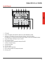
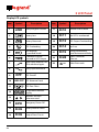
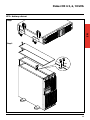
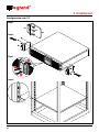
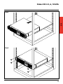
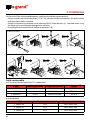
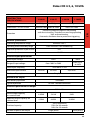
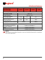
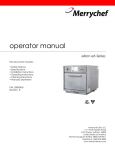
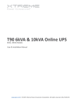
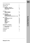
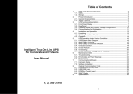
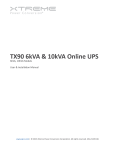
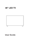
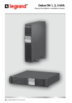
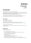
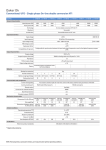
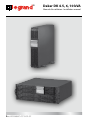
®
Daker DK 4.5, 6, 10 kVA
Manuel d’installation • Installation manual
Part. LE05380AC-07/13-01 GF
Daker DK 4.5, 6, 10 kVA
1 Introduction
26
2 Conditions of use
26
3 LCD Panel
27
4 Rear panel
29
5 Installation
31
6 UPS communicator self-diagnostic software
42
7 Possible malfunctioning
42
8 Technical features
43
25
EN
Index
®
1 Introduction
This manual contains information for users of the Daker DK 4.5, 6, 10 kVA models.
You are advised to read this handbook carefully before installing your uninterruptible power supply, meticulously following the instructions given herein.
The UPS Daker DK is only been made for civil or industrial use; it is not in conformity with the standards for electro-medical equipment.
In case of problems with the UPS, please read this manual before contacting technical support;
The “Troubleshooting” section can in fact help resolving most of the problems encountered while
using the uninterruptible power supply.
2 Conditions of use
• The UPS has been designed for the power supply of the data processing equipment; The load
applied must not exceed the one indicated on the rear label of your UPS.
• The ON/OFF button of your UPS does not electrically isolate the internal parts. To isolate your
UPS unplug it from the mains power socket.
• Do not open the UPS container since there may be parts inside with dangerously high voltage
even when the mains plug is disconnected; there are no parts inside that the user can repair.
• The front control panel is provided for manual operations; Do not press on the panel with sharp
or pointed objects.
• The UPS Daker DK has been designed to work in closed, clean rooms where there are no inflammable liquids or corrosive substances and where it is not too damp.
• Do not place near equipments that generate strong electro-magnetic fields and/or near equipments that are sensible to electro-magnetic fields. (engines, floppy disks, speakers, adapters,
monitors, video, etc...)
• Do not pour any liquid on the UPS or inside the UPS.
• Do not place the UPS in humid environment or near liquid, such as water, chemical solution…
• Do not expose the UPS to the direct sunlight or any heat sorces.
• Keep the ventilation slits clean to dissipate the heat of the UPS.
• Use grounded power cable to connect the UPS to the mains supply.
• Do not plug laser printers into the UPS because of their high start-up current.
• Do not plug house electric equipments, such as hair dryer,air conditioner, and refrigerator into
the UPS outlets.
26
Daker DK 4.5, 6, 10 kVA
3 LCD Panel
3
4
2
11
12
EN
1
5
9
10
8
6
7
1. LCD panel
2. Green LED indicates that the UPS is able to run under redundancy mode.
3. Solid green LED indicates that the utility input voltage is within the window.
Flashing green LED indicates that the utility input voltage is within the acceptable window.
4. Green LED indicates that Bypass Input is normal.
5. UPS ON/Alarm Silence
6. Go to previous page or change the setting of the UPS.
7. Confirm a changed setting.
8. Go to the next page.
9. UPS OFF Switch
10. Special functions log in/out
11. UPS is working under ECO (Economical) mode.
12. UPS alarm LED
27
®
EPO
Er05
Display LCD symbols
Item
Symbol
Er06
Utility or Bypass Source
17
Er10
Inverter Over-current
2
Battery Low
18
Er11
The UPS is overheated
3
Battery Abnormal
19
Er12
UPS Output Overloading
4
UPS Overloading
20
Er14
Fan Error
5
UPS Working
in specified mode*
21
Er15
Wrong Procedure to
Enter Maintenance Mode
6
A Blackout Transfer
occurred in UPS Output
22
Er28
Bypass Overload
Time out
7
Bypass Input Abnormal, UPS
fails to transfer to bypass
23
Er**
Other Error code
8
Utility Input Abnormal
Item
Symbol
1
LINE
9
10
OFF
Description
UPS Shutoff
LINE OFF UPS Abnormal Lock
11
UPS Flow Chart
12
4-Digit Measurement
Display
13
Indicates the item
to be measured
14
EPO
Emergency Power Off
15
Er05
Battery Weak or Dead
16
Er06
Output Short Circuit
Er10
28
3 LCD Panel
Er11
Description
Daker DK 4.5, 6, 10 kVA
4 Rear panel
14
19
15
RS232
13
EPO
Ext. Battery
G2
N22
G1
N1
3 100 56
3 100 57
L12
G
+
CB1
Utility Input
Breaker
16
20
17-18
20
17-18
16
19
Ext.
Battery
-
UTILITY
INPUT
BREAKER
EPO
G
+
14
3 100 58
3 100 59
CH B
SLOT
S1
RS232
BYPASS
INPUT
BREAKER
Not Intended to
TNV Communication
Network
ON OFF
US 6906501, TW 202668
19
20
13
3 100 53
3 100 54
PAT. NO.:
G1
INPUT
N1 L12
14
OUTPUT
G2 N22 L21
Utility Input
Breaker
EPO
Slot
15
L21-N22: UPS OUTPUT L12-N1: UTILITY INPUT
G2: OUTPUT EARTH G1:
INPUT EARTH
GROUND
GROUND
Parallel Work Comm.
Bus Not Intended to
TNV Communication Network
RS232
13
INPUT
L21
-
EN
Parallel Work Comm.
Bus Not Intended to
TNV Communication Network
OUTPUT
OFF
S1
ON
TB1
15
TB2
17-18
13. RS-232 Port
17. AC utility power connection
14. E mergency Power Off (EPO) Dry Contact
Signal inputs
18. AC Outlets power connection
15. Communication Card Options Slot
20. Cooling Fans
16. External Battery Connector
19. Utility Input circuit breaker
29
®
4 Rear panel
Interface Settings
3 100 53/54/55/56/57
OUTPUT
G2 N22 L21
G1
INPUT
N1 L12
L21-N22: UPS OUTPUT L12-N1: UTILITY INPUT
G2: OUTPUT EARTH G1:
INPUT EARTH
GROUND
GROUND
3 100 58
3 100 59
TB1
TB1
TB2
TB2
TB1
OUTPUT
TB2
INPUT
G2
G1
N1
N22
L21
UTILITY
BYPASS
L12
L11
DIM ONLY
TB1
OUTPUT
G1
G2
N22
L21
TB2
INPUT
N1
T
S
R
L11-N1 : clamps not used in this version
L12-N1 : clamps for connection to the UPS input line (3 100 58)
R-S-T-N1 : clamps for connection to the UPS input line (3 100 59)
G1: clamp for UPS input ground cable connection
L21-N22: clamps for UPS output connection
G2: 30
clamp for UPS output ground cable connection
Daker DK 4.5, 6, 10 kVA
5 Installation
Check for the following standard package contents:
• User Manual
• RS-232 communication cable
• Tower/Rack Accessories Kit as below:
3 100 53/54/56/57
A5
A6
A7
EN
A4
x1
x1
x2
x2
3 100 58/59
A8
A9
x1
A10
x1
x2
A7
x2
B4
A1
B3
B1
B2
x4
A3
x2
x2 2U
x2 3U
x2 4U
x1
S1
6.0
±1.0mm
M3
3 100 53/54/56/57 x8
3 100 58 x7
S2
6.0
±1.0mm
S3
8.0
±1.0mm
M3
M4
x8
x6
31
®
5 Installation
Tower configuration setup
Step 1
A1
A1
A1
A1
Step 2
Optional
32
Daker DK 4.5, 6, 10 kVA
UPS + battery cabinet
EN
Step 1
Step 2
A4
33
®
5 Installation
Configuration rack 19”
Step 1
B1
S3
Step 2
Step 3
90°
Step 4
34
B2
Daker DK 4.5, 6, 10 kVA
EN
Step 5
Step 6
35
®
5 Installation
On the rear of the uninterruptible power supply are the following connections:
• Output sockets and input connector (17) or (18): connect to these connectors the power cable
and the output cables included.
• Socket for connecting computer serial interface RS232 (9 female pins) [4]: required when using
the diagnostic and shutdown management software.
• Presetting for the connection of additional batteries [16].
3 100 53/54/56/57
A7
S1
A6
S1
A5
A4
S1
60 - 70
3 100 58/59
A7
S1
S1
A9
A10
A8
S1
Cable section table
a. AC input and output (minimum 75°C copper wire)
Model
Maximum Current
Conductor Section
Torque
3 100 53/56
25 A
2
AWG #10/4 mm
17.7/ 11 lb-in
3 100 54/57
33 A
2
AWG # 8/6 mm
17.7/ 11 lb-in
3 100 58/59
54.3 A
AWG # 6/10 mm2
23 lb-in
b. Entrée Batterie
36
Model
Maximum Current
Conductor Section
3 100 53/56
19 A
AWG #10/4 mm2
3 100 54/57
25 A
AWG #10/4 mm2
3 100 58/59
41 A
AWG #10/4 mm2
Daker DK 4.5, 6, 10 kVA
WARNING
For safety reasons it is advised not to modify the cables supplied; it is also necessary to make
sure that the mains socket the uninterruptible power supply is connected to is fitted with a
safe connection to the earth system, and appropriate protection in accordance with current
regulations.
WARNING
The mains supply socket, or the disconnection device, must be installed nearby the
equipment, and must be easily accessible.
Proceed to the installation as follows:
1) Position the uninterruptible power supply so that the vents are not obstructed.
2) Connect the input connector [17] or [18], the power cable, and the output cables to the
appropriate connectors [17] or [18].
3) Connect the loads to the output cables, ensuring that the switches of the various users are off.
4) Connect the power supply plug to a power socket with suitable voltage and current.
Start
1) Switch on the power breaker [19] of the distribution panel. Then the UPS will start up. Green
, and
show that the Utility and Bypass inputs are normal. The LCD will display
LEDs
OFF after few seconds.
2) The UPS is in Bypass Mode now. It will proceed to self-test automatically. If no abnormal message
appears then the pre-startup of the UPS was successful and the charger starts to charge the
batteries.
3) Press the UPS On Switch
[5] for approximately three seconds. The Buzzer sounds twice and
the LCD display changes from previous status to RUN mode.
4) The UPS is in self-test mode again. The LCD display will show TEST and the UPS will remain in
battery mode for approximately four seconds.
5) If the self-test fails an error code or error status will appear on the screen.
6) Your start-up operation of the UPS is complete now. Make sure the UPS is plugged into the wall
receptacle for charging at least 8 hours and the batteries are fully charged before connecting
the device to be protected.
Shutdown
7) Press the Off
[9] key for five seconds. The Inverter output will be turned off, and the output
load will be supplied by the Bypass loop.
8) Turn Off the Input breakers [19].
9) The UPS is now turned off completely.
37
EN
®
5 Installation
Default data and special function execution
After the UPS completely starts up, press the
key to change the LCD display to figure Q1.
Q1
buzzer “On”
Q2
buzzer “Off”
Press the
key to scroll through the UPS settings.
The LCD will display in sequence figure Q1 (buzzer) figure R1 (Self-test) figure S1 (Bypass
Voltage Windows) figure T (Output Frequency Synchronization Window) figure U (Inverter
Output Voltage)
figure V1 (UPS Operation Mode)
figure W (Output Voltage Micro Tune
Value) figure X (UPS Id) figure Y (Parallel function status).
R1
Self-test disable
R2
Self-test anable
S1
Bypass Voltage is adjusted
to narrow range
S2
Bypass Voltage is adjusted
to wide range
T
Frequency Window is +/-3 Hz
38
Daker DK 4.5, 6, 10 kVA
U
inverter output voltage
EN
V1
The UPS is operating
in “normal mode”
V2
The UPS is operating
in “Eco mode”
V3
The UPS is operating
in “CVCF 50 Hz mode”
V4
The UPS is operating
in “CVCF 60 Hz mode”
W
Output Voltage Adjustment
(-3% to 3%)
X
UPS position in parallel mode
Y
The parallel function is disabled
39
®
5 Installation
Press the scroll up
key to execute special functions.
The functions include buzzer ON (as in figure Q1), buzzer OFF (as in figure Q2, Alarm silence for
UPS Warning), and self-test OFF (as in figure R1) or self-test ON (as in figure R2).
The UPS will execute the battery test for ten seconds. If the self-test is successful it will display
figure E1; otherwise, it will display figure E2 and an error message at the same time.)
UPS Default Settings and their alternatives
Make sure the UPS is not “On”. Press the On
and scroll down
keys simultaneously for
approximately three seconds. The buzzer will sound twice, and the LCD will display figure Q1,
indicating that the UPS is in setting mode.
To scroll through the options press the
key to go DOWN and
to scroll up.
Except for Buzzer (figures Q1 and Q2) and Self-test (figures R1 and R2) all of the other default
settings may be changed by pressing the scroll up
key.
Figures S1 and S2 indicate the bypass input acceptable window. It can be 184-260 VAC or 195-260
VAC.
Figure T indicates the bypass frequency window of the Inverter Output. The acceptable setting
values are ±3 Hz and ±1 Hz.
Figure U indicates the acceptable Inverter Output Voltage. Possible values are 200, 208, 220, 230,
or 240 VAC.
Figures V1, V2, V3 and V4 indicate the operation modes of the UPS. Possible values are Online, Eco
(Economical) mode, fixed 50 Hz Output, and fixed 60 Hz Output.
Figure W indicates the adjustment of the Inverter Output, which may be set to 0%, +1%, -1%, +2%,
-2%, +3%, or -3%.
Figure X indicates the position of the UPS when the UPS is in Parallel mode. Possible positions are
1, 2, 3, and 4. The position must be 1 if the UPS is not in Parallel mode.
Figure Y indicates the parallel function status. “P 01” indicates that the parallel function is disabled,
and “P 02” indicates that the parallel function is enabled.
40
Daker DK 4.5, 6, 10 kVA
After changing settings you must scroll to the “save” screen (figure Z) and then press the enter key
to save all of your changes. Then the LCD will display figure AA to indicate completion of the
setting changes.
To cancel your changes rather than save them press and hold the “OFF” key
for five seconds. The
LCD displays figure AA directly, which indicates that your changes were canceled.
EN
Z
* Press the Enter key
to save changes.
AA
The UPS is locked.
Turn Off the Utility Input breaker.
Your setting changes are now complete.
Connection
The UPS has an RS232 serial communication interface that provide access, through a processor,
to a range of data for the operation and the history of the UPS.
This function can be accessed through a WINDOWS (*) interfacing program, connecting a
serial port of the PC to the interface socket that can be found on the back of the UPS using an
RS232 cable.
41
®
6 UPS communicator self-diagnostic software
From the website www.ups.legrand.com it is possible to download free of charge a self-diagnostic
software running on WINDOWS (16 e 32 bit) e Linux platforms.
This software can be used for the following functions:
- Display of all the operation and diagnostic data in case of problems.
- Setup of special functions.
- Automatic shutdown of the local computer (Windows and Linux operating systems).
* Windows is a registered trademark of Microsoft Corporation.
7 Possible malfunctioning
The UPS always operates on batteries:
• There is no line voltage
• Line voltage is out of allowed UPS range
• The power supply cable is not correctly connected to mains socket.
• The input circuit breaker has to be reset
• The mains socket is defective
The UPS signals overloading:
• Additional loads to the ones normally connected have involuntarily been connected on the
output line.
• Check all the loads connected to the output
The UPS doesn’t operate in battery mode (it shuts down or immediately signals it is close to the
operating limit):
• The UPS has operated with no mains voltage for a long time and has not been able to recharge
the battery. Recharge it for at least 6 hours by connecting the uninterruptible power supply to
the mains.
• The battery is flat due to not using the UPS for a long period. Recharge it for at least 6 hours by
connecting the uninterruptible power supply to the mains.
• The battery has run down due to being used frequently, to ambient conditions, or to having
exceeded its average service life; it is necessary to change it.
The UPS doesn’t deliver power to the output:
• Check that the loads are correctly connected to the output sockets
42
Daker DK 4.5, 6, 10 kVA
Construction Specifications
Weights
Dimensions L x H x P in mm
Protection
3 100 53
3 100 54
52 Kg
52 Kg
440 x 176 x 680
440 x 176 x 680
Electronic protection against overloading
and short-circuiting. Shutdown on
reaching operating limit and overheating.
Automatic shutdown due to protection
triggering
Ambient specifications
Operating temperature range
Operating relative humidity range
from 0 to +40 °C
from 20 to 80% non-condensing
Degree of protection as per IEC529
IP21
Noise level at 1 meter
< 50 dBA
Electrical input specifications
Rated input voltage
230 V
Range of input voltage
from 160 V to 280 V
Rated input frequency
50 or 60 Hz ± 5Hz
Maximum input current
25 Arms
Number of input phases
33 Arms
Single phase
Waveform on output
With battery operation
Type of operation
sinusoidal
on line - double conversion
Electrical specifications on output
Rated output voltage
230 V ± 2%
Active output capacity on nominal load
4050W
5.4KW
Apparent output capacity on nominal load
4.5KVA
6KVA
Overload capacity
Number of phases on output
105% continuous
120% for 30 seconds
140% for 10 seconds
Single phase
43
EN
8 Technical features
®
8 Technical features
Construction Specifications
3 100 53
3 100 54
Electrical specifications on output with battery operation
Rated output voltage
Output frequency
230 V ± 2%
50/60 Hz ± 0.5%
Active output capacity on non-linear load
4.05kW
5.4kW
Apparent output capacity on non-linear load
4.5kVA
6kVA
6 min.
4 min.
Battery operation
Operating time
Charging time to 90% of the load
Technical data and number of batteries
4 hours
n°20
maintenance- free,
sealed, lead
battery
12V
5Ah
n°20
maintenance-free,
sealed, lead
battery
12V
5Ah
Standards
Electromagnetic compatibility
Emission - Immunity
Conforms to EN 62040 - 2
Safety
Conforms to EN 62040 -1
Performance and features
Conforms to EN 62040 -3
NOTICE
The batteries are considered hazardous waste and should be disposed of in accordance with
current regulations.
44
Daker DK 4.5, 6, 10 kVA
Weights
Dimensions L x H x P in mm
Protection
3 100 56
3 100 57
25 Kg
25 Kg
3 100 58
3 100 59
26 Kg
440 x 88 x 680 440 x 88 x 680
440 x 132 x 680
Electronic protection against overloading
and short-circuiting. Shutdown on reaching operating
limit and overheating.
Automatic shutdown due to protection triggering
EN
Construction
Specifications
Ambient specifications
Operating temperature range
from 0 to +40 °C
Operating relative humidity range
from 20 to 80% non-condensing
Degree of protection as per IEC529
IP21
Noise level at 1 meter
< 50 dBA
Electrical input specifications
Rated input voltage
Range of input voltage
Rated input frequency
Maximum input current
230 V
380 V
from 160 V to 280V
from 227V
to 485V
50 or 60 Hz ± 5Hz
25 Arms
Number of input phases
33 Arms
54,3 Arms
Single phase
Waveform on output
With battery operation
sinusoidal
Type of operation
on line - double conversion
Electrical specifications on output
Rated output voltage
230 V ± 2%
Active output capacity
on nominal load
4.05kW
5.4 kW
9 kW
Apparent output capacity on
nominal load
4.5kVA
6 KWA
10 KWA
Overload capacity
Number of phases on output
105% continuous
120% for 30 seconds
140% for 10 seconds
Single phase
Three phase
45
®
8 Technical features
Construction
Specifications
3 100 56
3 100 57
3 100 58
3 100 59
Electrical specifications on output with battery operation
Rated output voltage
230 V ± 2%
Output frequency
50/60 Hz ± 0.5%
Active output capacity
on non-linear load
4.05kW
5.4kW
9kW
Apparent output capacity
on non-linear load
4.5kVA
6kVA
10kW
Charging time to 90% of the load
4 hours
5 hours
Standards
Electromagnetic compatibility
Emission - Immunity
Conforms to EN 62040 - 2
Safety
Conforms to EN 62040 -1
Performance and features
Conforms to EN 62040 -3
NOTICE
The batteries are considered hazardous waste and should be disposed of in accordance
with current regulations.
46