1
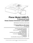
 Pic 1
Panamorph CineVista
Anamorphic Lens System
For Ceiling and Shelf/Table Mount Installations
CONTENTS AND HARDWARE LIST:
Pic 1:
Pic 2:
SUMMARY
The CineVista is a high performance anamorphic lens system designed
for both ceiling mounted and shelf mounted projectors to provide the
ultimate in true ultra wide entertainment. It is designed to be very easy to
install and is used with your projector’s aspect modes to display ultra wide
movies and PC games on a 2.35:1 or 2.40:1 aspect ratio screen.
One CineVista Anamorphic Lens
One CineVista Lens Mount with Lens Bracket attached
a) Qty 1 - 5/32” Gold Hex Key
b) Qty 1- 1/8” Gold Hex Key
c) Qty 2 - #10-32 ½” Black Hex Screw
d) Qty 2 - #10-32 ½” Black Metal Washer
e) Qty 2 - #10-32 ½” Knurled Washer
h) Qty 1 – 9” x 2” x1/2” Foam Spacer
Hardware for Chief SLB installation (bent sides)
f) Qty 4 - 3/8” Plastic Spacer
g) Qty 4 - #10-24 1 ½” Stainless Steel Screw
1 FOR OPTIMUM PERFORMANCE
•
The only additional piece needed to complete the lens system installation is to attach
the CineVista Lens to the Lens Bracket once the projector and lens mount are both
ceiling mounted.
•
Once the CineVista Lens is attached to the CV Mount, final adjustments are made to
center the lens in front of the projector’s lens and fine tune the image on the screen.
Range of focal distance from screen to projector: 8 - 18 feet (2.4 to 5.4 meters).
Ratio of projector throw distance to screen height: 2.5 x screen height minimum installation
distance. Optimal installation range of 3 to 3.5 times screen height. It is not recommended
to place your projector further back than a throw ratio of 4.5 times screen height.
Mounting configurations: 1) ceiling mounted (i.e. projector feet "up") and 2) shelf (or table
top) mounted. If shelf mounted, the lens bracket or the lens mount should be attached to the
shelf for stability.
INSTALLATION STEPS
1.
Perform a standard installation of your projector. For safety, we recommend that two
people be involved whenever the projector is lifted on or off the ceiling mount. If you are
using a Chief SLB bracket and the bracket sides are bent up on the sides, please use
the additional hardware provided (Page 1, Pic 3) for the SLB installation.
2.
It is also recommended that, when installing the Chief mount, that the top half of the
projector mount be oriented such that the locating slots are facing the back of the
projector and pointed away from your projector screen. The image below shows the
correct orientation.
3.
Make sure that the projector’s lens is horizontally aligned with the center line of the
screen and that the image is not tilted left to right relative to the top and bottom of the
screen border (key-stoned). Be sure that the projector ceiling mount is properly
installed, since the anamorphic lens system will add weight to the front of the projector.
The CineVista system weight is 11 lbs, which does not include the projector weight.
Optimum vertical position of the projector: +/- 20% of screen height from the top or bottom
edge of the screen.
Design tip: Minor variations from these instructions will typically not cause noticeable effects
on image quality. However, a small throw ratio (ratio of throw distance to screen height) will
likely result in the image being cut off at the edges. Overall, a larger ratio is recommended.
EQUIPMENT REQUIREMENTS
•
Projector: 16:9 front projector (HD preferred) with required aspect modes. See the
Aspect Mode Chart on page 4 for necessary modes and names. If your projector does
not have the necessary aspect modes, an external video processor including a few Bluray players and A/V receivers have this ability or an external scalar can properly scale
the image instead.
•
Projector Ceiling Mount: Chief RPA series projector mounts are recommended either
using the RPAU universal projector attachment or a projector specific SLBxx
attachment bracket. The pictures in this manual use an SLB attachment bracket for
clarity.
•
Screen: 2.35:1 or 2.40:1 aspect projection screen
INSTALLING THE CINEVISTA LENS MOUNT
CEILING MOUNT OVERVIEW
•
The CineVista Mount and Lens Bracket are shipped pre-assembled to make installation
as simple as possible.
•
The CineVista Mount (CV Mount) installs between the top and bottom halves of your
projector’s ceiling mount.
2 4.
5.
Once you have the projector properly aligned with the screen, CAREFULLY loosen the
Quick-Disconnect thumb nuts and allow the projector/mount to drop down until there is
enough space between the top and bottom halves of the projector mount for the CV
Mount to fit in between them. A second person is recommended to lightly hold the
projector and stabilize it.
Swing the CineVista lens bracket all the way in so that it is close to the projector. Then,
bracing the projector from the back, insert the CineVista mount between the top and
bottom halves of the Chief mount and slide it back until the back edge of the lens
bracket rests 1/2” from the front of the projector’s lens or the front of the projector body
(whichever is closest to the CineVista lens).
6.
To help insure that an adequate distance is obtained a foam “spacer”(h) is included in
the installation kit. Place this spacer along the front of the projector and slide the CV
Mount into place until the back of both arms of the CV Lens Bracket touch the spacer
evenly.
7.
Tighten the Quick-Disconnect thumb nuts to stabilize the unit. Check to make sure the
projector is still properly centered on the screen and the top and bottom of the image
aligns with the screen. Adjust the image if necessary.
3 INSTALLING THE CINEVISTA LENS
1.
Swing the arms that hold the CineVista Lens Bracket back out to their fullest extension
away from the projector and prepare to install the lens. You will need one of the #10-32
x ½” screws (c) and black metal washers (d) for each side of the bracket as well as a
#10-32 x ½” Knurled Washer (e) and the 1/8 Gold Hex Key (b).
3.
Once the CineVista Lens is installed, swing it into place in front of the projector’s lens.
The CineVista Lens should be centered horizontally on the projector’s lens and should
have approximately ¼” between the back of the CineVista lens and the front of the
projector’s lens or housing.
4.
There are three adjustments for positioning the CineVista Lens:
a) There is a Pivot Screw (B) on top of the Adjustment Block that allows the lens to
slide side-to-side along the front of the projector;
b) The Swing Arms (C) attached to the lens bracket adjust the distance between the
CineVista lens and the front of the projector;
c) The lens bracket Adjustment Screws (A) can be used to raise or lower the lens so
that the light beam from the projector shoots through the CineVista lens cleanly.
5.
Turn on the projector. REMOVE THE PROTECTIVE FILM ON THE FRONT OF THE
CINEVISTA LENS or the image will be blurry.
TUNING IN LENS TILT AND SHIFT
This is the core step of the setup so please be patient!
2.
Holding the CineVista lens between the two “forks” of the lens bracket, place one of the
knurled washers between the lens and the fork. Then take one of the #10-32 x ½”
metal washers (d) and place it over one of the screws (c) and insert the screw through
the fork into the receiving hole in the side of the CineVista Lens. Repeat the process
for the other side of the lens and snug the screws down but do not fully tighten them.
1.
Use the projectors lens shift to move the image vertically so that it appears to be
centered on the screen. Once the 16x9 image is satisfactory swing the CineVista lens
into place in front of the projector’s lens.
2.
Loosen the lens bracket Adjustment Screws (A) and slide the CineVista lens up or
down until the beam is firing through the center of the lens. Make sure the lens bracket
Adjustment Screws are roughly even in their vertical slot position or the image will show
an irregular geometry from right to left.
4 3.
Adjust the rotation of the CineVista so that the left and right sides of the image are an
equal distance from their respective screen borders. Now tighten the Pivot Screw (B)
on top of the CV Mount Adjustment Block using the 5/32” Hex Key.
5.
For optimum multiple aspect ratio performance, adjust the projector’s zoom so that a
1.85:1 aspect ratio movie is just masked by the top and bottom of the screen border.
This way 1.85:1, 16:9 and 2.35-2.40:1 aspect ratio movies should all be presented to fill
the screen at a constant height.
PROJECTOR SETTINGS WHEN USING THE CINEVISTA
To enjoy an Ultra-Widescreen 2.35:1 movie it is necessary to use two “aspect modes”.
These modes are either in your projector or in an external device such as a scaler, some
blu-ray players and some a/v receivers.
The first aspect mode is a “vertical stretch” setting which is used for ultra wide content. This
removes the letterbox bars from a 2.35:1 image by stretching the image vertically. The
CineVista lens corrects the vertically stretched image geometry to fill your ultra wide screen.
The second aspect mode is 4:3 mode. This mode is used when watching 16:9 HD content
like TV shows or standard widescreen movies (1.78:1 or 1.85:1).
CHART 1 – Aspect Modes Please consult your projector’s instructions for these settings
and how they are activated.
Aspect Mode Names
4.
Adjust the vertical position and tilt of the CineVista Lens so that the projector beam is
passing through the center of the Lens and so any residual pincushion distortion (an
inward curvature to the image) is about the same at the top and bottom of the image.
Tilting the lens up or down on its axis will even out this curvature. This will typically
result in the CineVista Lens being below the center of the projector lens and tilted
downward slightly. Tighten the lens bracket Adjustment Screws (A) to lock the lens in
place.
Projector
Manufacturer
For Watching Ultra
Wide Movies
For Watching TV or
Standard Widescreen
Movies
BenQ
Letterbox (LB)
4:3 Mode
DPI
TheaterScope Mode
4:3 Narrow
Epson
Anamorphic Wide
Horizontal Squeeze
InFocus
Letterbox Mode
4:3 Mode
JVC
Anamorphic A
Anamorphic B
Mitsubishi
Anamorphic 1
Anamorphic 2
Optoma
Letterbox
4:3 Mode
Panasonic
V-Fit
4:3 Mode
Runco
Letterbox
4:3 Narrow
Sharp
Anamorphic 2.35:1
Anamorphic 16:9
SIM2
Letter Box
4:3 Mode
Sony (HW50)
V-Stretch
Squeeze
Sony
Anamorphic Zoom
Normal
ViewSonic
Anamorphic 1
Anamorphic 2
Vivitek
Letter Box
4:3 Mode
5 CLEANING
In most applications lenses do not need very much cleaning – a bit of dust will not impact
image clarity. However, in today’s high performance home cinemas with very dark rooms a
small build-up of dust or other foreign matter on your projector lens or your Panamorph lens
can produce a measurable reduction in contrast. The most effective cleaning approach is to
simply blow off any dust. If there is any residue or build-up then it is recommended that you
clean the optics with professional lens cleaning supplies such as from a camera store while
the lens is in front of the lit beam of the projector. This will allow you to quickly see both the
results of cleaning and also if you are causing any damage.
LIMITED WARRANTY
Panamorph, Inc. warrants this product to be free of defects in original workmanship and material for a period of eighteen
months from the date of manufacture listed on or inside its shipping container. During this period, a defective unit may be
repaired or replaced, at the discretion of Panamorph, Inc., by returning it in its original packaging with a copy of your receipt.
This warranty does not cover damage resultant from lack of prudent care, accident or misuse (including the use of motor
systems with lenses or other products in ways not intended), or any cosmetic damage not reported within 15 days of
purchase. Damages are limited to the cost of the product. A service charge may be applied to any returned product requiring
cosmetic attention, or to the repair of any damage not covered under this warranty.
Panamorph, Inc.
This warranty is non-transferrable and applies only to products and/or components purchased by original end users
through authorized Panamorph channels operating in compliance with Panamorph1755
policies,
terms and
conditions.
Telstar
Drive,
Suite 103
Colorado Springs, CO 80920
719-266-2680
www.panamorph.com 6