1
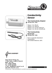
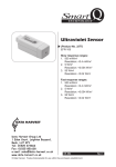
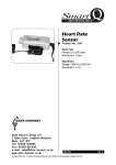
Smart
Q
TECHNOLOGY
Rotary Motion
Sensor
(Product No. 3280)
Ranges:
• Angular position:
0 - 360 degrees
Resolution: 0.1 degree
• Angular velocity (revs.):
±4 rev/s
Resolution: 0.01 rev.
• Angular velocity (rads.):
±40 rad/s
Resolution: 0.1 rad.
• Linear Distance: ±200 mm
Uses the Linear Rack accessory
Resolution: 0.1 mm
• Distance: ±200 mm
Using the 11 mm Pulley
Resolution: 0.1 mm
DATA HARVEST
Data Harvest Group Ltd
1 Eden Court, Leighton Buzzard,
Beds, LU7 4FY
Tel: 01525 373666
Fax: 01525 851638
e-mail: [email protected]
www.data-harvest.co.uk
• Distance: ±2,000 mm
Using the 31 mm Pulley
Resolution: 1 mm
• Distance: ±2,000 mm
Using the 49 mm Pulley
Resolution: 1 mm
• Pendulum: ±20 degrees
Resolution: 0.1 degree
DS 055
© Data Harvest. Freely photocopiable for use within the purchasers establishment.
No 4
Smart
Q
Rotary Motion Sensor
TECHNOLOGY
Contents
Introduction...............................................................................................
The Sensor...............................................................................................
Clamping the Sensor................................................................................
Connecting...............................................................................................
Power requirements.................................................................................
To set the range........................................................................................
Linear displacement.................................................................................
Using the Pulley ranges: 11 mm, 31 mm, and 49 mm........................
Using the Linear Rack range..............................................................
Angular displacement...............................................................................
Using the Angular Position range.......................................................
Using the Pendulum range.................................................................
Angular velocity........................................................................................
Using the Revolutions or Radians a second range.............................
Maintenance.............................................................................................
Investigations...........................................................................................
Using Pre or Post log functions................................................................
Removing an offset from a set of data................................................
To calculate velocity from motion data................................................
To calculate acceleration from motion data........................................
Warranty ................................................................................................
1
2
3
3
4
4
5
5
7
8
8
8
9
9
10
10
10
10
11
11
12
Introduction
The Smart Q Rotary Motion Sensor is a low friction bi-directional position sensor,
which can be used to perform a variety of investigations into rotational mechanics.
The Rotary Motion Sensor can be used to measure directly:
• Linear displacement by using any of the pulley ranges or the linear rack.
• Angular displacement using the angular position or pendulum range.
• Angular velocity using either the revolutions or radians per second range.
The Smart Q Rotary Motion Sensor is equipped with a micro controller that greatly
improves its accuracy, precision and consistency. The micro controller contains the
calibration for 8 different ranges making it a versatile Sensor for a wide range of
laboratory investigations. The stored calibration for the selected range is
automatically loaded into EASYSENSE when the Rotary Motion Sensor is
connected.
The Rotary Motion Sensor is supplied with a steel rod (size 80 mm long x 10 mm
diameter with a M6 thread). This support rod can be screwed into the mounting
threads, which are found on four sides of the Sensor. The rod can be used for
clamping into a suitable holding device e.g. a retort stand, in many different
orientations.
Smart
Q
Rotary Motion Sensor
TECHNOLOGY
The Sensor
Inside the body of the Sensor is an optical encoder disc fitted to the shaft of the
Sensor. When the shaft of the Sensor is turned the optical encoder disc will cut
through a light source and produce a pulse each time the beam is interrupted. The
optical encoder will give a maximum of 1024 counts per revolution of the Sensors
shaft.
The information provided by the pulses has been used to provide data for eight
ranges. These are:
1. Distance: ±200 mm using the 11 mm pulley.
2. Distance: ±2000 mm using the 31 mm pulley.
3. Distance: ±2000 mm using the 49 mm pulley.
4. Angular position: 0 - 360 degrees.
5. Pendulum: ±20 degrees.
6. Angular velocity (rads.): ±40 radians per second.
7. Angular velocity (revs.): ±4 revolutions per second.
8. Linear distance: ±200 mm using the linear rack.
Mounting thread
Locating ridge for the
optional spoked pulley
Locating pins for the optional
angular momentum disc
Square slot for the
optional linear rack
Retaining screw
(M3 thread)
Mounting thread
Mounting thread
Three-tier pulley
Reset button
Product code 3280
Rotary Motion
Sensor
Mounting thread
Cable connector
Indents for the optional
pendulum rod
On the front of the Sensor is a three-tier pulley. The diameter of the larger pulley is
49 mm, the centre pulley is 31 mm and the smallest pulley is 11 mm.
The reset button is located on the left side of the Sensor. This button will act as a
tare and when pressed will set the output of the Sensor to centre point of the scale.
This point will be at approximately zero for all ranges apart from angular position,
which will be 180º.
Due to the physical characteristics of the encoder wheel there may need to be some
Smart
Q
Rotary Motion Sensor
TECHNOLOGY
further fine adjustment made for absolute zero. The best method of making this
adjustment is by minute tilting of the body of the Sensor or a small manipulation of
the shaft.
Note: If it is not possible to set the Sensor to zero, the offset from the Sensors reading can be removed in
the EASYSENSE software, see page 10.
Some of the features visible on the Rotary Motion Sensor are guides for
accessories available to purchase separately. These accessories are:
• The linear rack, pendulum rod and angular momentum discs, which are
available as the Rotary Motion Accessory pack - Product No. 3288.
• The Spoked Pulley - Product No. 3177.
Clamping the Sensor
The Sensor needs to be held securely when used in an investigation.
For example:
• Clamp the mounting rod in a boss - only the rod
should be clamped, not the body of the Sensor. If
the body of the Sensor is clamped it may distort
the case and set the shaft out of alignment.
• Rest the Rotary Motion Sensor on the bench to
prevent it from moving.
• Clamp the retort stand to the bench.
• Keep the distance between the Sensor and the
boss as short as possible to reduce flexing.
• Level the Sensor (vertically or horizontally
depending on its orientation in use) as accurately
as possible to prevent uneven wear on the axle
bearings.
Connecting
Push one end of the sensor cable (supplied with the
EASYSENSE unit) into the shaped socket on the
side of the Sensor.
Connect the other end of the sensor cable to the
input socket on the EASYSENSE unit (with the
locating arrow facing upwards).
The EASYSENSE unit will detect that the Rotary
Motion Sensor is connected and will display the
currently selected range. If the range is not suitable
for your investigation, set to the correct range
(see page 4).
Sensor cable
with locating
arrow facing
upwards
Input socket
Rotary Motion
Sensor
0
328
de n
t co tio
duc Mo
Pro otary nsor
R Se
•
•
•
Smart
Q
Rotary Motion Sensor
TECHNOLOGY
Power requirements
When connected to an EASYSENSE unit, this Sensor will be permanently powered.
It will draw a lot of current (i.e. 60mA) so we recommend the EASYSENSE unit
is connected to its mains power supply when used with this Sensor for extended
periods of time.
EASYSENSE Flash Logger users:
• We recommend the Pocket PC should be connected to an external power
supply when used with this Sensor.
• There is a limit to the power that can be supplied from a CompactFlash slot (the
minimum specified tolerance is 100 mA at 3.3 V). The EASYSENSE Flash
Logger takes 35 mA at 3.3 V; the Rotary Motion Sensor takes 60 mA, which
means that the two used together are near the CompactFlash slots minimum limit (60 mA & 35 = 95 mA). We therefore recommend that the Rotary Motion Sensor be best used on its own when connected to the Flash Logger.
Note: The Flash Logger will be protected by its built-in short circuit protection should this limit be exceeded.
To set the range
•
•
•
•
•
Connect the Rotary Motion Sensor to the EASYSENSE
unit.
Start the EASYSENSE program and select one of the
logging modes from the Home page e.g. EasyLog.
Select Sensor Config from the Settings menu.
Select the Rotary Motion Sensor from the list (it will be
listed using its current range) and click on the Change
Range button.
The current range will be highlighted. Select the
required range and click on OK.
Close Sensor Config. Click on New
and then Finish
for the change in range to be detected by the logging
mode.
The range setting will be retained until changed by the user.
With some EASYSENSE units it is possible to set the range from the unit. Please
refer to the EASYSENSE unit’s user manual.
Smart
Q
Rotary Motion Sensor
TECHNOLOGY
Linear Displacement
Using the Pulley ranges: 11 mm, 31 mm, and 49 mm
If a length of thread is run in the groove of the pulley wheel and turns the pulley as it
moves, the distance moved by the thread can be calculated.
The accuracy of the distance results is affected by the thickness of the string used.
The calibration for the stored pulley ranges was calculated using 1.5 mm diameter
string run in the groove of the pulley. For accurate results use 1.5 mm diameter
string or rod.
Pulley
Diameter
Direction of the decreasing
Number of complete
Distance distance reading (looking at the revolutions travelled
Sensor from the pulley front).
over range
Distance in mm
travelled each
revolution
11 mm
±200 mm
Clockwise
±5.662
31 mm
±2000 mm
Clockwise
±21.11
94.74
49 mm
±2000 mm
Clockwise
±12.94
154.56
The pulley on the Rotary Motion Sensor is graduated with
three different sizes. The smallest pulley has a diameter
of 11 mm and can measure over a distance of ±200 mm.
The other two pulleys have a diameter of 31 and 49 mm
and will both measure over a distance of ±2000 mm.
The pulley can be set up to record the distance moved by
an object by either using a thread over the pulley wheel or
a rod resting on/in the pulley wheel/groove.
35.32
49 mm pulley
31 mm
pulley
11 mm
pulley
Using a thread over the pulley:
1. Decide which diameter pulley is the most suitable for your investigation. Set this as the selected range (see page 4).
2. Clamp the Rotary Motion Sensor in a stand using its rod attachment.
3. Cut a suitable length of 1.5 mm thread. Attach one end of the thread to the test object and the other end to a small mass (to apply a tension to the thread).
4. Run the thread in the groove of the selected pulley. Check that when the test object is moved the pulley runs freely.
5. With the test object secured at its start position and the small mass applying
tension to the thread, press the reset button on the side of the Rotary Motion Sensor to set to near zero.
Note: Slight manipulation of the body of the Sensor may be necessary to set absolutely to zero.
6. Start recording and release the test object to record the change in distance.
Smart
Q
Rotary Motion Sensor
TECHNOLOGY
This method would be useful for:
• Attaching to a spirometer to measure breathing patterns.
• Investigating motion/forces
using the Dynamics system.
Rotary Motion
Sensor
TECHNOLOGY
Smart
and d
own
Retort
Stand
p
Pull u
Sticky
Tape
Q
Sound
Sensor
DATA HARVEST
• Recording the distance moved by a Sensor
e.g. investigating resonance in a pipe with a
Sound Sensor.
Cord
Loud
Speaker
Using a metal or wooden rod:
A rod can be used instead of thread e.g. when a tensioned mass will create
unwanted movement. Follow the same procedure but instead of using thread attach
a 1.5 mm diameter metal or wooden rod to the object that will be moved. Rest the
rod in the groove of the selected pulley.
For example: This set
up could be used to
measure the
movement of a gas
syringe barrel in
a rate of reaction
investigation.
Syringe 100 cm
Temperature
Sensor
Bung
Delivery tube
Metal or
wooden rod
Retort stands
Rotary Motion
Sensor
Smart
Q
Rotary Motion Sensor
TECHNOLOGY
Compensating for a different diameter rod or string
The calibration for the pulley ranges was calculated using 1.5 mm diameter string.
If a different diameter rod or string is used then measurements for distance travelled
may be incorrect and a correction factor will need to be calculated for your data.
Mark a point on the pulley wheel being used. Mark a point on the string/rod and with
the string/rod resting in/on the rim of the pulley wheel, match up the two marks. Use
the string/rod to rotate the pulley for one complete rotation and mark the string/rod
again. Measure the distance between the two points on the string/rod and work out
the correction factor needed.
Example:
162 mm
Pulley Diameter Distance calibrated for each revolution (mm)
11 mm
49 mm Pulley
35.32
31 mm
94.74
49 mm
154.56
The measured distance between the two marked points on the string/rod for one
revolution using the 49 mm pulley was 162 mm. The calibration is calculated at
154.56 mm per revolution so the correction factor is = 162
= 1.05 mm
154.56
Select Pre or Post-log Function from the Tools menu, select Preset function,
General, Multiply by a constant, click on Next, select the Rotary Motion sensor as
the channel (e.g. Pulley 11 mm), click on Next, alter the channel name to identify it
as the corrected data set (e.g. Pulley 11 mm adj.) and enter the correction factor as
the number to multiply by (e.g. 1.05) into the parameters box, Finish.
Using the Linear Rack range
When this range is selected the Rotary Motion
Sensor will accurately measure linear
displacement of ±200 mm when used with the
optional Linear rack from the Rotary Motion
Accessory pack - Product No. 3288. The linear
rack is toothed and will turn the gear wheel
attached to the encoder shaft. This accessory
is suitable for applications where distance
needs to be measured without any other forces
being introduced e.g. tension or pull.
A mini c-clamp is provided in the Accessory pack, which enables a Smart Q
Sensor to be secured to the linear rack. Used this way the position of a Sensor can
be recorded as it is moved in an investigation e.g. inverse square law using a Light
level Sensor or change in field strength between magnets using the Magnetic field
Sensor.
Smart
Q
Rotary Motion Sensor
TECHNOLOGY
Angular Displacement
Using the Angular Position range
When this range is selected the Rotary Motion Sensor will record from 0 - 360
degrees, which is one complete revolution of the pulley shaft.
Centre point of the scale for this range is 180º, so when the reset button is pressed
the Sensor will return a value of near 180º.
Note: Slight manipulation of the body of the Sensor may be necessary to set absolutely to 180º.
This range is suitable for large angle pendulums.
Using the Pendulum range
When this range is selected the Rotary Motion Sensor will record ±20 degrees from
the resting vertical.
The Pendulum range is suitable for most pendulum experiments.
A simple pendulum
•
•
•
•
•
•
•
•
•
Clamp the mounting rod in a boss and rest the base of the
Sensor on the bench top to prevent the Rotary Motion Sensor
from moving. Position the retort stand so that the pendulum
wire will hang freely over the surface edge.
Set either Angular Position or Pendulum as the selected range
(see page 4).
Attach a mass to the end of a length of stiff wire.
Loosen the screw in the centre of the front pulley
wheel so a small gap is created between the
Mass
attached to
head of the screw and the shaft.
a length of
Make a small hook at the other end of the wire
stiff wire
and place in the gap.
Tighten the screw to secure the wire.
With the pendulum hanging still and freely at rest, press the reset button on the Sensor.
Start the EASYSENSE software and select Graph from the Home page. From
the logging wizard select a recording time of 10 seconds, to start logging at a
fixed reference point e.g. trigger when the pendulum rises above a value of 0.000.
Swing the pendulum, click on the Start icon, logging will start when the trigger condition set is met.
Smart
Q
Rotary Motion Sensor
TECHNOLOGY
Optional Rotary Motion Accessory Pack
Both the Angular Position and Pendulum range are suitable
for use with the optional Pendulum rod and masses from
the Rotary Motion Accessory pack - Product No 3288. The
Pendulum rod can be used for both pendulum and
rotational inertia investigations.
Angular Velocity
Using the revolutions or radians a second range
The Rotary Motion Sensor can record angular velocity either in radians per second
or revolutions per second. As the shaft of the Sensor is rotated the optical encoder
disc cuts through a light source and interrupts the light beam. The length of these
interruptions is used to calculate the angular velocity.
When the Ang revs. range is selected the displayed value will be shown as the
number of revolutions per second. When Ang rad. is selected values will be in
radians per second.
Angular velocity is a measure of the angle moved through
per second. A radian is an alternative measurement of
angle commonly used in physics instead of degrees.
Object takes time (t) to move through angle (θ).
θ
Angular velocity = rads-1
t
1 radian = 57.296º
Full Circle = 360º = 2π rad = 6.28 rad
Half Circle = 180º = π rad = 3.14 rad
Optional Rotary Motion Accessory Pack
Both these ranges are suitable for use with both
the Angular momentum disc set and the Pendulum
rod and masses from the optional Rotary Motion
Accessory pack - Product No. 3288. These
accessories can be used to investigate moment
of inertia, rotational collisions and conservation of
angular momentum.
r
θ
Speed round
the circle is
constant
Smart
Q
Rotary Motion Sensor
TECHNOLOGY
Maintenance
If the Rotary Motion Sensor is not moving as freely as expected place a drop of light
machine oil (e.g. 3 in 1) at the two bearings points:
1. On the spindle at the back of the Sensor.
2. Between the three-tier pulley and the body of the Sensor.
Spin the pulley several times so the oil will fully penetrate the bearings.
Investigations
•
•
•
•
•
•
•
Motion kinetics trolley.
Atwood’s machine.
Rates of reaction: volume of gas collected in a gas syringe.
The study of pendulums and simple harmonic motion.
With a spirometer to measure breathing patterns.
Conservation of mechanical energy.
Distance moved by a Smart Q Sensor.
When used with the optional Rotary Motion Accessory pack (Product No 3288)
• Conservation of angular momentum.
• Moments of inertia.
• Pendulum investigations.
• Gravitational rotational energy.
• Frictional torque.
• Rotational collisions.
• Rotational inertia.
• Newton’s second law in its rotational form.
• Tracking movement in a circle.
• Linear displacement of an object or Smart Q Sensor.
Using Pre or Post log functions
Removing an offset from a set of data
If it is/was not possible to set the Sensor to zero, the offset from Sensor’s reading
can be removed either:
• As the data set is created using a Pre-log Function or
• On data already recorded using a Post-log Function
Note: You will need to know the tare value before using these functions e.g. by using Test Mode from the Tools menu.
1. Select either Pre or Post-log Function from the Tools menu.
2. Select Preset function, choose General from the drop-down menu, then Tare, click on Next.
10
Smart
Q
Rotary Motion Sensor
TECHNOLOGY
3.
4.
Select the channel the function should be applied to (e.g. Pulley 11 mm), click on Next.
Alter the channel name to identify it as the corrected data set (e.g. Pulley 11 mm adj.) and enter the tare value into the parameters box, Finish.
Note: Make the tare value negative or positive as appropriate, e.g. (2) – (2) = 0, (-2) – (-2) = 0.
To calculate velocity from motion data
Note: If you intend to differentiate data recorded by the Rotary Motion Sensor, it is best to record using an
intersample time of 50 ms or more.
1.
2.
3.
4.
Select either Pre or Post-log Function from the Tools menu.
Select Preset function, chooseMotion from the drop-down menu, then
Velocity, click on Next.
Select the position or distance channel the calculation should be applied to (e.g. Pendulum), click on Next.
Edit the units as appropriate
e.g. deg/s and Finish.
Alter the display to show data
channels on both axes (an X/Y graph):
1. Select X-Axis from the Display
menu.
2. Select Channel as the X-axis.
3. Click to left of or below the axis
to alter the channel displayed.
To calculate acceleration from motion data
Note: If you intend to differentiate data recorded by the Rotary Motion Sensor, it is best to record using an
intersample time of 50 ms or more.
1.
2.
3.
4.
Select either Pre or Post-log
Function from the Tools menu.
Select Preset function, then
Motion from the drop-down
menu, then Acceleration
(second derivative from
position or distance data),
click Next,
Select the position or distance
channel the calculation should
be applied to (e.g. Pendulum),
click on Next.
Edit the units as appropriate e.g. deg/s/s and Finish.
11
Smart
Q
Rotary Motion Sensor
TECHNOLOGY
Warranty
All Data Harvest Sensors are warranted to be free from defects in materials and
workmanship for a period of 12 months from the date of purchase provided they
have been used in accordance with any instructions, under normal laboratory
conditions. This warranty does not apply if the Sensor has been damaged by
accident or misuse.
In the event of a fault developing within the 12 month period, the Sensor must be
returned to Data Harvest for repair or replacement at no expense to the user other
than postal charges.
Note: Data Harvest products are designed for educational use and are not intended for use in industrial,
medical or commercial applications.
WEEE (Waste Electrical and Electronic Equipment) Legislation
Data Harvest Group Ltd are fully compliant with WEEE legislation and are pleased to provide a disposal service for any of our products when their life expires. Simply return them to us clearly identified as ‘life expired’ and we will dispose of them for you.
12