1
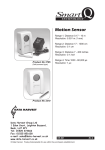
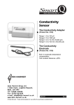
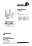
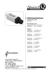
Smart Q TECHNOLOGY Count/Tachometer adapter (Product No. 3296) Ranges: Counts: 0 to 1,000 count Counts: 0 to 60,000 count Counts per second: 0.00 to 200.00 cps Revolutions per second: 0.00 to 200.00 rev/s Revolutions per minute: 0 to 12,000 rpm Wind speed m/s: 0.0 to 50.0 m/s Wind speed mph: 0.0 to 110.0 mph Rain Gauge: 0 to 2,500 mm Spoked Pulley m/s: 0.00 to 5.00 m/s Spoked Pulley mph: 0.00 to 10.00 mph Spoked Pulley m: 0.000 to 50.0 m DATA HARVEST Data Harvest Group Ltd. 1 Eden Court, Leighton Buzzard, Beds, LU7 4FY Tel: 01525 373666 Fax: 01525 851638 e-mail: [email protected] www.data-harvest.co.uk DS 104 © Data Harvest. Freely photocopiable for use within the purchasers establishment No 1 Smart Q Count/Tachometer adapter TECHNOLOGY Introduction ................................................................................................................................ 2 Connecting................................................................................................................................. 3 Ranges ...................................................................................................................................... 3 Altering the currently selected range: ............................................................................... 3 Information about ranges:.......................................................................................................... 4 1. & 2. Cumulative count................................................................................................... 4 3. Counts per second....................................................................................................... 4 4. Revolutions per second ............................................................................................... 4 5. Revolutions per minute ................................................................................................ 4 6. & 7. Wind speed in m/s & mph ..................................................................................... 5 8. Rain gauge................................................................................................................... 6 9. & 10. Speed using the Spoked pulley in m/s & mph..................................................... 6 11. Distance using the Spoked pulley in m....................................................................... 6 Practical information .................................................................................................................. 8 Warranty .................................................................................................................................... 9 Introduction On/Off indicator Sensor cable socket for connection to an EASYSENSE logger Zero reset button Mini din socket for Smart Q digital sensor 3.5 mm jack socket The Count/Tachometer adapter counts electrical pulses (the number of times a change in a digital signal occurs). What it counts will depend on the device attached to the Adapter e.g. attach a magnet and reed switch to a bicycle wheel and measure its speed by counting the revolutions. The Count/Tachometer contains the calibration for 11 different ranges making this a very versatile sensor for a wide range of investigations e.g. recording wind speed, rain fall, revolutions per minute, counts per second and more. There are two sockets for connecting devices to the Count/Tachometer. 1. A mini din socket, which will accept any Data Harvest Smart Q digital sensor e.g. Light gate (Product No. 3250) with or without Spoked pulley (Product No. 3177), Crocodile clip lead set (Product No. 3260), Push button reaction switch (Product No. 3261), Timing mats set (Product No. 3255). 2. A jack socket, which can be used with a switch type device, connected via a 3.5 mm jack plug e.g. an Anemometer (Product No. 3297), Rain Gauge (Product No. 3298), Foot switch (Product No. 3299) or contact (magnetic) switch, push-to-make switch, pressure mats, etc. Press the button on the Adapter to reset a count to zero. The Adapter will start to count a soon as it detects a pulse. The red LED will give a visual indication of the state of the device attached; it will light while the condition is ON (low). 2 Smart Q Count/Tachometer adapter TECHNOLOGY Connecting Light gate connected via the mini din socket Switch connected via the jack socket Connect the device to be used to either the mini din or jack socket as appropriate. Push one end of the sensor cable (supplied with the EASYSENSE unit) into the hooded socket on the Adapter. Connect the other end of the sensor cable to an input socket on the EASYSENSE unit. The EASYSENSE unit will detect that the Count/Tachometer is connected and display values using the currently selected range. The Count/Tachometer will reset its count to zero: a. When you press the zero button. b. Automatically when you connect the Adapter to an input on a logger c. Automatically when a range is changed. The Count/Tachometer takes its power direct from the EASYSENSE unit. It will use power while connected (even when it is not taking any samples). Disconnect the Adapter when not in use. Ranges The Count/Tachometer has eleven ranges. Altering the currently selected range: Connect the Count/Tachometer to the EASYSENSE unit. Start the EASYSENSE program and select one of the logging modes from the Home screen. Select Sensor Config from the Settings menu. Select the Count/Tachometer from the list and click on the Change Range button. The current range will be highlighted. Select the required range and click on OK. Close Sensor Config. Click on New and then Finish for the change in range to be detected. The range setting will be retained until changed by the user. With some EASYSENSE units it is possible to change the range from the unit. Please refer to the EASYSENSE unit’s user manual. 3 Smart Q Count/Tachometer adapter TECHNOLOGY Information about ranges: RANGES: 1. Cumulative count - 0 to 1,000 2. Cumulative count - 0 to 60,000 These ranges count the number of times the Count/Tachometer detects the change in a switch from OFF to ON. The reset button on the Count/Tachometer can be used to reset a count to zero. A constant can be applied to a count to give another unit. For example, to convert count data to distance travelled: Attach a switch to a wheel that is ON each time there is a complete revolution of the wheel. Use Tools, Post-log Function, Preset, General, Multiply by a constant. Alter the name to Distance, the units to m and enter the number to multiply i.e. the distance between each count (one revolution of this road bike = 2.0 metres). The larger range, 0 to 60,000, can be used to improve the accuracy of low speed counting. For example attach 4 triggers equally spaced on the wheel to attenuate a switch; it will then be ON each time a ¼ of the wheel passes by i.e. every 0.5 m. If the count reaches the maximum value, it will stop counting. Investigations: • Use with switches e.g. push-to-make, proximity (magnetic), pressure mats or a foot switch to count a total number of events. • Count the number of people entering a room. Use a trigger as a start condition to begin recording. • Use as a tally counter with a push button switch e.g. to count the number of cells seen in a square. 3. Counts per second - 0.00 to 200.00 cps (200 Hz) 4. Revolutions per second - 0.00 to 200.00 rev/s 5. Revolutions per minute - 0 to 12,000 rpm These ranges use the time elapsed between ON conditions to calculate the rate per second or minute. A rolling average filter is applied to the data over 5 readings. The revolutions ranges can be used to measure the number of full rotations around a fixed axis e.g. speed of a wheel, shaft or disc. Investigations: • Muscle fatigue using a Light gate • Study circular motion e.g. shaft rotation of a waterwheel • Electrical energy vs. shaft speed • Use a home made Anemometer to measure wind speed in revolutions per second (rev/s) To convert revolutions per second values to velocity first work out the circumference (in meters) of the circle made by your anemometers rotating cups. Multiply the wind speed in 4 Smart Q Count/Tachometer adapter TECHNOLOGY rev/s by the circumference of the circle, and you will have an approximation of the velocity of at which your anemometer spins (in meters per second). Tools ► Post-log Function ► Formula ax2 + bx + c, Next ► select Rev/s as channel X, Next ► 2 rename the channel e.g. Anemometer and units as m/s ► make a = 0 (to delete the ax part of the equation), make c = 1 so the equation is in effect bx, make b = the circumference of the circle, Finish. • Monitoring the speed of an exercise bike Use an exercise bike with a magnet attached to one of the bike spokes which triggers a reed switch. Connect the reed switch to the Adapter by either using a Smart Q Crocodile clip or wire the switch to a lead ending with a 3.5 mm jack plug. Increasing exercise Resting Recovery Polar Heart rate sensor Count/Tachometer The effect of exercise on Heart rate Ranges dedicated to accessories: 6. Wind speed in m/s - 0.0 to 50.0 m/s 7. Wind speed in mph - 0.0 to 110.0 mph These two ranges are calibrated for the 3297 Anemometer to record wind speed in either m/s or mph. Connect one end of the jack lead (supplied with the Anemometer) to the jack socket at the base of the Anemometer and the other end to the jack socket on the side of the Adapter. Investigations: • Weather patterns Notes: Wind speed must be at least 1 m/s (2 mph) to achieve start up speed. Maximum wind speed is 50 m/s or 110 mph. 5 Smart Q Count/Tachometer adapter TECHNOLOGY The Anemometer uses a double contact reed switch, so counts twice for each complete rotation. Wind speed is calculated by using the rate of rotation of the wind cups. (m/s = (Hz x 0.786) + 0.948, mph = (Hz x 1.758) + 2.121). When recording over a long duration on battery power some EASYSENSE loggers e.g. Q Advanced, sleep between samples. The Count/Tachometer will continue to update its readings while the logger is in sleep mode and return the current speed at the time the sample is taken. The Count/Tachometer takes its power direct from the EASYSENSE unit. It will use power while connected (even when it is not taking any samples). If recording for a long period we recommend attaching the logger to its mains power supply. 8. Rain gauge – 0 to 2,500 mm This range is calibrated for use with the 3298 Rain Gauge; a ‘tipping bucket’ type rain gauge. As rain falls it lands in the funnel-shaped top, which leads the water down into a ‘bucket’ (self-emptying spoon). The spoon is balanced on a pivot and held by a magnet that is in contact with a switch. The magnet exerts just enough tension so it will release its hold when the spoon is full causing the bucket to tip, empty and return to its normal position in one quick movement. When the bucket tips it triggers the switch from normally closed (ON) to open (OFF). Total rainfall is measured by counting how many times the bucket tips. Connect the jack lead from the Rain gauge to the jack socket on the side of the Adapter and then connect the Adapter to the logger. The LED will light when a count is detected. Investigations: • Weather patterns Notes: The Rain gauge range reacts to switch changes in a different way to the other ranges. As the rain gauges switch is normally closed (ON) it looks for a change from closed to open (OFF). If this range is selected without the rain gauge attached the red LED will remain lit until it is connected. The act of plugging in the Rain gauge after the Adapter has been connected may add 1 to the reading, press the button on the Adapter to reset to zero. When recording over a long duration on battery power some EASYSENSE loggers e.g. Q Advanced, sleep between samples. The Count/Tachometer adapter will continue to update its readings while the logger is in sleep mode and return the current speed at the time the sample is taken. The Count/Tachometer takes its power direct from the EASYSENSE unit. It will use power while connected (even when it is not taking any samples). If recording for a long period we recommend attaching the logger to its mains power supply. 9. Speed using the Spoked pulley in m/s - 0.00 to 5.00 m/s 10. Speed using the Spoked pulley in mph - 0.00 to 10.00 mph 11. Distance using the Spoked pulley in m - 0.000 to 50.000 m These ranges are calibrated for use with the 3177 Spoked pulley attached to a Light Gate. As the Pulley rotates its spokes will block the infrared beam of a Light Gate. 6 Smart Q Count/Tachometer adapter TECHNOLOGY The calibration for Spoked pulley ranges is calculated by measuring the circumference of the pulley wheel using 1.5 mm diameter string run in the groove of the pulley and dividing the total by 10 (10 spokes). For accurate results use 1.5 mm diameter thread or rod resting in the pulley wheel/groove. Note: As the spokes on the pulley can easily interrupt the Light Gates beam, wait until all is ready before resetting to zero and then begin logging. Investigations: • Record the speed or distance travelled by a Dynamics cart • Record the speed or distance travelled by a road bicycle (with the Spoked pulley in contact with the bicycle wheel) • Newton’s 2nd law - using Atwood’s machine or a cart on a horizontal track Newton’s 2nd law using Atwood’s machine: 1. Make sure the S Pulley in m/s range is selected and connect the Count/Tachometer to a Light gate / Spoked pulley. 2. Select Graph from the Home screen, a total time span of 2 seconds, 20 ms interval; and a trigger of rises above 0.10 m/s. Select Overlay. 3. From the Tools menu select Pre-log Function, Preset function, Motion, Acceleration from Velocity data, Next. Select S.Pulley as the velocity channel, Next. Alter the units to m/s2. 4. Support the weights, after a second the Count/Tachometer will auto reset to zero, click on Start to begin logging and release the weights. 5. Transfer a weight from one side to the other and repeat. 6. Select the sloped part of the graphs (Edit, Use Selection). Use Smoothing (Tools menu) to smooth the Acceleration graphs. Use Show Statistics (Analysis menu) to read off the mean value for each acceleration graph. Use Sensor Settings (Options icon or right click to left of graph) to alter the axis limits to a suitable value. 7 Smart Q Count/Tachometer adapter TECHNOLOGY Practical information • The fastest speed that data can be captured is 50 Hz (20 ms). If an intersample time of less than 20 milliseconds is selected, then the values obtained will either default to the lowest reading or the set up will be rejected by the logger/software. • Light Gate: The count will increase by 1 each time the infrared beam is blocked (ON – red LED lit). It will ignore the change when the infrared beam is unblocked (OFF – red LED off). ON Blocked Count +1 Unblocked OFF OFF Push button reaction switch: The count will increase by 1 when the button is pressed. Pressure mat: The count will increase by 1 when someone stands on the mat. Crocodile clips: The count will increase by 1 each time the circuit in which the crocodile clips are connected is completed. • There is an input voltage limit of a minimum of 0 V to a maximum of 5 V for devices that can be attached to the Count Tachometer. • If you wish to assemble your own switches the typical connections to a 3.5 mm plug are: C B B C B B A A A STEREO Jack plug A + C = Signal (shorted together) B = Power (pulled up to 5 V via 2k2 resistor) A MONO Jack plug A = Signal B = Power (pulled up to 5 V via 2k2 resistor) • Switches often don't make and break cleanly when switched; they actually open and close their contacts several times before settling down to new position. This effect is commonly called "switch bounce" and can last from as little as a fraction of a millisecond (ms), to as long as 50 ms. To reduce the effect of bounce a time delay has been implemented so that contact bounce has time to settle before being counted i.e. 3 ms for the Cumulative count ranges, 1 ms for Counts per second and Revolutions per second or minute, 2 ms for the Rain gauge. Even with this delay there will still be some switches that aren’t suitable for counting e.g. a tilt switch. It is best to test your switch and setup before beginning a count. • When recording over a long duration on battery power some EASYSENSE loggers e.g. Q Advanced, sleep between samples. The Count/Tachometer adapter will continue to update its readings while the logger is in sleep mode and return the current value at the time the sample is taken. • The Count/Tachometer adapter takes its power direct from the EASYSENSE unit. It will use power even when it is not taking any samples. Disconnect the Adapter when not in use to conserve power. If recording for a long period we recommend attaching the EASYSENSE unit to its mains power supply. • The effect of signal errors will increase as the length of an extension cable increases until eventually the signal will degrade (this effect is reduced by using good quality cable). The Anemometer and Rain Gauge has been tested with a 10 metre 3.5 mm male/female jack extension cable (20 metres of cable total) without degradation of the signal. 8 Smart Q Count/Tachometer adapter TECHNOLOGY • The Count/Tachometer adapter will reset its count to zero: a. When you press the zero button. It starts counting when you release the button. b. Automatically when you connect the Adapter to an input on a logger c. Automatically when a range is changed. • There is not enough resolution on the Spoked pulley encoder wheel to make this sensor suitable for recording the velocity of a pendulum. Warranty All Data Harvest Sensors are warranted to be free from defects in materials and workmanship for a period of 12 months from the date of purchase provided they have been used in accordance with any instructions, under normal laboratory conditions. This warranty does not apply if the Sensor has been damaged by accident or misuse. In the event of a fault developing within the 12-month period, the Sensor must be returned to Data Harvest for repair or replacement at no expense to the user other than postal charges. Note: Data Harvest products are designed for educational use and are not intended for use in industrial, medical or commercial applications. WEEE (Waste Electrical and Electronic Equipment) Legislation Data Harvest Group Ltd are fully compliant with WEEE legislation and are pleased to provide a disposal service for any of our products when their life expires. Simply return them to us clearly identified as ‘life expired’ and we will dispose of them for you. 9