1
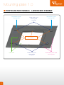
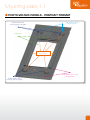
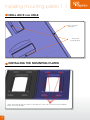
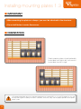
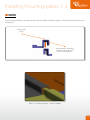
GSE INTEGRATION
INSTALLATION MANUAL
For photo-voltaic systems
partially covering the roof
V 7.5
WWW.GSEINTEGRATION.COM
Contents
STEP BY STEP
Presentation of system
p.4
Contents of kit
GSE Integration mounting plates
Tools required for installation
Mounting the plates
GSE Integration system installation sequence
p.5
p.6 - 7
p.8
p.9 - 16
p.17 - 31
Servicing and replacing a module
p.32
Assistance
p.33
Contact
p.34
Examples of completed installations
p.36 - 37
3
Presentation of system
GSE INTEGRATION SYSTEM
The GSE Integration system is used to install modules on all types of roofing, in partial coverage (channel
tiles, mechanical, flat, slates), on new buildings or buildings being renovated.
The system may be installed in portrait format or in landscape format, with a specific mounting plate for
each format, on both small installations (less than 3 kWp) and large roofs (several hundred kWp).
The GSE Integration system may be installed on wood or metal structures and mounted on battens or
lathing. It can also be mounted directly on common rafters and can be installed on slopes between 15°
and 50°.
The GSE Integration system is guaranteed for 10 years, providing the installation recommendations given
below are respected. The system does not require much maintenance, except for regular cleaning of the
solar panels.
4
Contents of kit
ASSEMBLY ACCESSORIES
2
1
3
5
4
EDGE JOINERS
8
6
7
9
10
11
MOUNTING PLATES
12
14
13
WATERPROOFING
15
ASSEMBLY
ACCESSORIES
EDGE JOINERS
16
17
MOUNTING PLATES
WATERPROOFING
6 - roof angle joiners
12 - stainless umbrella screw
15 - waterproofing strip
1 - stainless umbrella screw
7 - roof crest joiner
2 - neoprene seal
8 - pop rivet
13 - portrait format
mounting plate
16 - roll of precompressed
seal strip
3 - double clamps
9 - lateral edge joiner
17 - under-roof screen
4 - single clamps
10 - junction joiner
14 - landscape format
mounting plate
5 - hook plates
11 - seal
5
Mounting plate 1.0
PHOTO-VOLTAIC PANELS - LANDSCAPE FORMAT
Stop receiving upper
mounting plate
Photo-voltaic panel
mounting plate
and guide
Stop receiving upper
mounting plate
Mounting point
on structure
Cable outlet
6
Photo-voltaic panel
mounting plate
and guide
Photo-voltaic panel raised
mounting plates
Mounting plate 1.1
PHOTO-VOLTAIC PANELS - PORTRAIT FORMAT
Stop receiving upper
mounting plate
Photo-voltaic panel
mounting plate and guide
Cable outlet
Mounting point
on structure
Photo-voltaic panel raised
mounting plates
Photo-voltaic panel
mounting plate and guide
7
Tools required for installation
CHALK LINER
PERCUSSION SCREWDRIVER
MEASURING TAPE
© Lucaz80 - Fotolia.com
8
Installing mounting plates 1.0
ESSENTIAL POINTS TO OBSERVE WHEN INSTALLING
MOUNTING PLATES AND CLAMPS
MAX. SPACING BETWEEN RAFTER CENTRES: 600 mm
MAX. SPACING BETWEEN BATTEN CENTRES: 350 mm
MAX. SPACING BETWEEN PURLIN CENTRES: 500 mm
MINIMUM BATTEN THICKNESS:
15 mm for rafter centres spacing 400 mm
27 mm for rafter centres spacing 600 mm
EXPANSION
Expansion computing
Expansion coefficient of PP20T 0.75 to 1.25 x 10⁻⁴ / K
Length
1.00 10-4 / K
2.00 m
Delta Température 20 à 80°
Expansion value
60.00°C
13 mm
Delta Température 20 à -20°
Expansion value
40.00°C
8.00 mm
Coefficient dilatation du bois 0.5 x 10⁻⁴ / K
Longueur
0.5 10-4 / K
2.00 m
Delta Température 20 à 80°
Valeur de dilatation
60.00°C
6.5 mm
Delta Température 20 à -20°
Valeur de dilatation
40.00°C
4.00 mm
The difference in expansion between the mounting plate material and wood necessitates drilling an 8 mm hole
in the rim, at the clamp mounting points and also at the points where the mounting plate is screwed to the
structure, using the 5.5 mm diameter screws, supplied.
9
Installing mounting plates 1.1
DRILL AN 8 mm HOLE
In the rim, to mount
the clamps
At the plate
mounting points
INSTALLING THE MOUNTING PLATES
Attach the mounting plate at 6 points, in the recesses in the studs and in the central protection
(points shown by red dots)
10
Installing mounting plates 1.2
INSTALLING THE CLAMPS
(fig:2)
1
2
3
The clamps are only mounted on the mounting plate rim (fig:2)
Mount the clamp (3) using the stainless self-tapping screw (1) (supplied complete with grey EPDM washer).
Do not use steel screws.
It is essential to install the black EPDM seal (2) (supplied) under the clamp (between the mounting plate
and the clamp).
The rims are only drilled to mount the clamps (no other holes are drilled)
A screw, diameter 5.5 mm (supplied in the kit) should be screwed in at 1800
rpm, with a loading of 30 kg.
Result should be as shown in DTU 40.35 or DTU 40.36
Insufficient
correct
Too much
MOUNTING THE RIMS
2 clamps per rim
2 clamps per rim
11
Installing mounting plates 1.3
IMPORTANT
• When mounting the plates or clamps, you must be attached to the structure.
• Do not drill holes in water flow zones.
ORIENTATION
Panel mounting plates should preferably
be installed from right to left, but can also
be installed from left to right.
• The photo-voltaic field rating must meet the requirements of standard NF C 15-100, of ETU guide C15-712 and
of the practical guide issued by the French authorities, to ensure safety and the proper operation of the photovoltaic system.
12
Installing mounting plates 1.4
NOTE
Care should be taken to ensure that the mounting plates overlap properly, for the interlocking system to be
waterproof.
Mounting the
clamps
Superimposition and locking
together of the photo-voltaic
panel mounting plates.
View of 4 mounting plates, locked together
13
Installing mounting plates 1.5
ADJUSTING GSE INTEGRATION PLATES
GSE Integration plates are adjustable* (in the direction of the slope) as a function of panel size. In order to
facilitate the adjustment of the GSE Integration panels, graduations are marked on the overlapping zone.
PORTRAIT FORMAT PANEL
Example: The plate H1640-80 mm x L992 mm
accepts a panel of :
Height from 1640 to 1680 mm
Width 992 mm
Graduated
overlapping zone
LANDSCAPE FORMAT PANEL
Ex : La plaque L1640 Example: The plate L1640 mm x H992-1032 mm
accepts a panel of : Width 1640 and Height from 992 to 1032 mm
Graduated
overlapping zone
*Please refer to sizes table
14
Installing mounting plates 1.5
ADJUSTMENT EXAMPLE
PORTRAIT FORMAT PANEL (H1640-80mm X L992mm)
For a panel of H1650, the plate should be positioned 10 mm to the rear.
For a panel of H1660 = 20 mm to the rear.
Graduated
overlapping zone
LANDSCAPE FORMAT PANEL (L1640mm X H992-1032mm)
For a panel of H1002 the plate should be positioned 10 mm to the rear.
For a panel of H1012 = 20 mm to the rear.
Graduated
overlapping zone
15
Acceptable tolerance per model
ACCEPTABLE TOLERANCES FOR PHOTO-VOLTAIC PANELS
ON OUR GSE INTEGRATION PLATES
PORTRAIT FORMAT PANELS
PANEL TOLERANCES
MODEL
WIDTH (mm)
HEIGHT (mm)
1640-80/992
987-993
1600-1680
1640-80/1001
996-1002
1600-1680
1580-1620/808
803-809
1540-1620
1575-1615/1082
1077-1083
1535-1615
1575-1615/1046
1041-1047
1535-1615
1575-1615/1069
1064-1070
Graduated
overlapping zone
1535-1615
Height tolerance
Width tolerance
LANDSCAPE FORMAT PANELS
PANEL TOLERANCES
MODEL
WIDTH (mm)
HEIGHT (mm)
1640/992-1032
1635-1641
952-1032
1650/992-1032
1645-1651
952-1032
1660/992-1032
1655-1661
952-1032
1670/992-1032
1665-1671
952-1032
1675/992-1032
1670-1676
952-1032
1680/992-1032
1675-1681
952-1032
1580/808-848
1575-1581
768-848
1575/1082-1122
1570-1576
1042-1122
1559/1082-1122
1554-1560
1042-1122
Graduated
overlapping zone
Height tolerance
16
Width tolerance
Installation phases 1.0
The under-roof screen must be approved for roofing, classified E1 or pending technical approval and classified
W1 as per standard EN13859-1. The under-roof screen must be installed in compliance with French building
regulations CSTB 3651-2.
Height of field
Height of field
PREPARATION OF ROOFING
Calculate the area
of your photo-voltaic field
Landscape
Portrait
1) Remove the roofing elements over the area computed above.
2) Remove one extra row of tiles on the right and on the left (two rows for slates or flat tiles).
3) Then remove the roofing elements over the height computed above.
4) Remove one more row of tiles at the top (two rows for slates or flat tiles).
17
Photo-voltaic field
computed above
Photo-voltaic field
computed above
slate roof :
2 more rows removed
tile roof :
1 more row removed
Installation phases 2.0
INSTALLING THE WATERPROOFING STRIP
2.1) In the case of a shallow slope or thick roofing elements (e.g. channel tiles) or very shaped roofing elements, in order to
avoid standing water, install two 10 cm strips over the batten supporting the lowest row of tiles, over the entire width of the
field. The strips should be sufficiently thick to enable the water to run off properly.
2.2) Apply the roll of waterproofing strip (preferably
self-adhesive) on the strips or batten.
2.3) Fold back the upper edge of the waterproofing
strip around 2 cm.
2.4) Fold back the right and left ends in the same
way.
2.5) Firmly press the waterproofing strip onto the
first row of tiles, pressing it down smoothly and
carefully (ensure that you don’t create any water
trap zones)
2.6) Installation on channel tiles requires a
waterproofing strip 45 to 56 cm wide. (standard
width 28 cm)
INSTALLING THE FIRST ROW OF MOUNTING PLATES
3.1) Using the chalk liner, mark a line on the
waterproofing strip, parallel to the battens and 15 cm
to 20 cm below the top edge of the waterproofing
strip.
3.2) Position the first mounting plate in the bottom
right-hand corner of the uncovered area, aligned
with the chalk liner mark. Install the mounting plate
(see mounting recommendations on pages 9 to 13).
Rims
3.3) Using red chalk or a red line marker, mark the various points
at which the rims will be over the battens or purlins on which the
mounting plates are to be fixed, and the clamps used to mount
the photo-voltaic panels.
(See mounting recommendations, pages 9 to 13)
18
Installation phases 3.0
INSTALLING THE FIRST ROW OF MOUNTING PLATES
Place, the second mounting plate next to the
first one, taking care to plug the rims together
properly. Proceed in the same way for the
remaining mounting plates.
INSTALLATION THE FOLLOWING ROWS OF
MOUNTING PLATES
Install the second row of mounting plates from
right to left. The top mounting plate should
just overlap the lower mounting plate, until in
contact with the dedicated stops.
19
Installation phases 4.0
INSTALLING LATERAL WATERPROOFING SKIRTS
Position the lateral waterproofing skirts overlapping the rims on the
right and left edges of the integration system.
Install a self-tapping screw on the join between two skirts. Screw it
through the mounting plate rims, into a batten or purlin.
(1)
Mount the skirt onto the batten
using hook plates (1).
(1)
The skirts plug into each other.
1) Open the lateral clip over 10 to 15 cm (lower skirt).
2) Plug in the upper skirt.
3) Mount the skirt on the rim while maintaining pressure.
4) Fold the clip.
Upper skirt plugs onto the lower skirt.
Open the lateral clip over 10 to 15 cm.
Position and install the upper skirt and
clip, and close the clip.
Adjacent lateral skirts should overlap by 15 cm.
20
Installation phases 4.1
INSTALLING THE PRECOMPRESSED SEAL
PLACE THE PRECOMPRESSED
SEAL ON THE LATERAL
EDGE JOINERS, UNTIL THE
WATERPROOFING STRIP IS
ENTIRELY COVERED.
The precompressed seal should be placed as close as possible to
the edge joiner clip.
21
Installation phases 5.0
INSTALLING THE PHOTO-VOLTAIC PANELS
Place the first row of panels on the mounting plates.
The panel is installed on the 2 upper studs.
PASSING THE CABLES (1)
Note :
Cables must transit from one panel to the next through the dedicated cable outlets:
Slot through the central protection pad.
1
2
(2)
PASSING THE
CABLES
22
Installation phases 6.0
PASSING THE CABLES (2)
Panels should be connected horizontally when installed in portrait format.
The panel can be installed upright or inverted.
ELECTRICALLY EARTHING THE PANELS
The photo-voltaic panel should be earthed through the dedicated hole in alloy frame
of the photo-voltaic panel
BLOCK DIAGRAM FOR SINGLE STRING WIRING
Good wiring practice is to limit the INDUCED loop lengths
Chassis earthing
Inverter DC input
AC BOX
INVERTER
DC BOX
Panels earthed directly on the
house earthing stake.
Earthing terminals
23
Installation phases 7.0
MOUNTING THE PHOTO-VOLTAIC PANELS (1)
Mount the panels in pairs, using the dual clamps. Install the EPDM seal, supplied with the screw, and
the washer, under the clamp, so that the assembly is waterproof when tightened (see page 11)
Mount the single clamps through the lateral skirts, aligned with the dual clamps already installed. Use selftapping screws with washers. Install the EPDM seal, supplied with the screw, and the washer, under
the clamp, so that the assembly is waterproof when tightened (see page 11)
The clamps MUST be mounted on a batten or purlin.
Depending on the battens (and their spacing) on which the clamps are being mounted, space the
clamps as evenly as possible in relation to the size of the mounting plate.
The clamp should be mounted between 1/5 (minimum) and 1/3 (maximum) from the edge of the panel.
MOUNTING THE PHOTO-VOLTAIC PANELS (2)
The number of clamps required depends on
the climatic zone of the installation.
Region
Quantity
Quantity
with Wind of standard of special
NV65
clamps
clamps
I
4
/
II
4
/
III
4
/
IV
4
/
V
4
/
For zones with stronger winds, a strengthener should be incorporated
for each clamp. In this case, 4 reinforced clamps are sufficient
(specify when ordering)
24
Installation phases 8.0
INSTALLING THE TOP EDGE JOINERS
The roof ridge edge joiner cannot be installed if the ridge interferes with the installation, or if there is reverse slope
due to panel thickness and a shallow slope on the roof (see recommendation on page 26).
In this case, the ridge edge joiner should be replaced by a waterproofing strip (see recommendation on page 21).
SEE CSTB TEST « COMBINED WIND/RAIN WITHOUT SEAL AND WITHOUT RIDGE EDGE JOINER ».
REPLACING THE RIDGE EDGE JOINER
BY A WATERPROOFING STRIP
Install the precompressed seal
When installing the precompressed seal on the lateral edge joiners,
the flashing strip must be entirely covered.
25
Installation phases 8.1
INSTALLING THE TOP EDGE JOINERS
Mount the corner bead at the correct height (see page 22),
then position the central edge joiner. Position the angle edge
joiner so that one side overlaps the central edge joiner and
the other side overlaps the lateral skirts (vertically) by at least
100 mm.
Join the two edge joiners using the « Ridge joiner » roofing
plate, 400 mm wide, over the two mounting plates. Apply two
vertical beads of PU adhesive on each side of the « Ridge
joiner » plate, to ensure that the roofing is waterproof.
Mount the ridge edge joiners and the lateral edge joiner using
the mounting hook plates (1), which should be screwed onto
a strip or a lath.
Apply 2 seals of PU adhesive between
the ridge junction (on each side)
and the central ridge
Roof ridge angle
The angle edge joiner provides
the junction with the central edge
joiner, overlapping it by at least
100 mm. Apply two vertical beads
of PU adhesive to ensure that the
roofing is waterproof.
(1)
26
Installation phases 8.2
UNIVERSAL RIDGE ANGLE
Recommended installation as a function of the various panel thicknesses
Note: The new universal ridge angle forms a join by overlapping the central edge joiner.
No specific recommendation for installing on panels 35 mm thick
Follow the instructions below to install the new angle edge joiner on photo-voltaic panels 40, 45 and
50 mm thick.
DRILLING
(only when installing panels 40, 45 and
50 mm thick)
Drill an 8 mm hole in the angle and the first lateral edge joiner
After drilling the two holes 1, insert the screw with a washer 2.
1
2. Screw and washer
3. EPDM washer
or packing shim seal
1.b
Under these two elements1,
install an EPDM washer3 (screw it onto the screw) which will provide 5 mm packing.
To install the angle on a panel of:
- 40 mm: install 1 shim3 / 45 mm: install 2 shims3 / 50 mm: install 3 shims3
27
Installation phases 8.3
UNIVERSAL CENTRAL EDGE JOINER
Corner bead
Use the pop rivets supplied with the kit and mount the corner bead on the central edge joiner. Each
hole corresponds to a panel thickness. The first hole is used when installing the central edge joiner
with panels 50 mm thick, the second hole for 45 mm panels, the third hole for 40 mm panels and
the last hole for 35 mm panels.
35
45
40
50
35
45
40
50
35
45
40
50
35
45
40
50
Corner bead front view
IMPORTANT !
Ridge angle
The angle edge joiner provides the junction with the central
edge joiner, overlapping it by at least 100 mm. Apply two
vertical beads of PU adhesive to ensure that the roofing is
waterproof.
28
Installation phases 8.4
MINIMUM ROOF SLOPE FOR INSTALLING RIDGE EDGE
JOINERS, AS A FUNCTION OF THE THICKNESS OF THE
PV PANELS.
SLOPE OF RIDGE EDGE JOINER MUST NOT BE LESS THAN 2°
Ridge edge joiner
Length
Sensor height
Slope
Flat section
SENSOR THICKNESS
MINIMUM ROOF SLOPE (°)
PENTE DE TOIT MINIMUM (%)
35
40
46
50
17
18
20
21
31%
33%
37%
39%
A batten of X mm may
be installed
Length
Sensor height
Slope
Flat section
3 mm BATTEN
MINIMUM ROOF SLOPE (°)
MINIMUM ROOF SLOPE (%)
6 mm BATTEN
SENSOR THICKNESS
35
40
46
50
17
18
20
21
31%
33%
37%
39%
MINIMUM ROOF SLOPE (°)
MINIMUM ROOF SLOPE (%)
This information is only a guide.
Care should be taken to ensure that all roofing regulatory requirements are met.
29
SENSOR THICKNESS
35
40
46
17
18
20
50
21
31%
33%
37%
39%
Installation phases 9.0
INSTALLING THE PRECOMPRESSED SEAL
(recommended size : L 20mm / H 40mm)
11.1) Unroll the precompressed seal over the entire height of the lateral skirts up to covering the
waterproofing strip (bottom of installation).
11.2) Unroll the precompressed seal over the entire width of the ridge edge joiners.
11.3) The edges of the two seals form a butt join (no overlapping).
Precompressed seal
30
Installation phases 9.1
FINISHING THE PHOTO-VOLTAIC FIELD
12.1) Install the additional rows of tiles (or slates) that were initially removed in the lateral zone
and at the top.
12.2) Cut the tiles if necessary.
The precompressed seal must cover the flashing
strip.
31
Servicing
INSPECTION
It is important to check once per year whether any leaves or other elements have penetrated under the photovoltaic system. Such elements can be blown out using a compressed air blower. Do not use solvent to clean the
mounting plates, which are in polypropylene.
It is recommended that you offer your customers a maintenance contract, which would include an annual
inspection of: generation, electrical system, panels, panel mounting plates, mountings, precompressed
seals, waterproofing strip.
REPLACING A MODULE
1) Remove the clamps from the panel to be replaced.
2) Disconnect the earthing connection and disconnect it from the string.
3) Remove the panel being replaced and position the new panel.
4) Connect the new panel to earth and to the string.
5) Mount the clamps.
The equipotential connection must be maintained
32
Assistance
TRAINING
Training courses are held on the first Monday
of every month (76380 Canteleu).
Specific training may be provided if requested
by a sufficient number of persons.
For any question, please contact your sales
manager and/or distributor.
TECHNICAL DEPARTMENT / ASSISTANCE DEPARTMENT
TECHNICAL ASSISTANCE IS AVAILABLE,
MONDAY TO FRIDAY, 8 am to 6 pm
16 QUAI GUSTAVE FLAUBERT 76380 CANTELEU
Tél. 02 32 10 77 60
Mail : [email protected]
33
Contact
GSE INTEGRATION
Your distributor :
34
Examples of completed installations
35
Examples of completed installations
36
GSE INTEGRATION is a GROUPE SOLUTION ENERGIE
patented development programme
www.segroup.fr
GROUPE SOLUTION ENERGIE
155-159 rue du Docteur Bauer. 93400 SAINT OUEN - Tél. : +33(0)1 70 32 08 00 - Fax : +33(0)1 70 32 08 01- email: [email protected]