1
The E-machine : supporting the teaching of program execution dynamics
by Samuel Dellette Patton
A thesis submitted in partial fulfillment of the requirements for the degree of Master of Science in
Computer Science
Montana State University
© Copyright by Samuel Dellette Patton (1989)
Abstract:
The teaching of computer programming contains aspects that are found in few other disciplines. The
mixture of syntactic and semantic knowledge required for programming is enough to overwhelm many
beginning students. An earlier attempt at addressing this problem resulted in a software system called
DYNAMOD. DYNAMOD is a library of expertly constructed Pascal programs and an interpreter that
displays the execution of these programs on a computer video terminal in a step by step fashion under
user control, effectively demonstrating the dynamics, or meaning, of a program. As a "proof of
concept" system, DYNAMOD is quite successful, but it suffers from several limitations. Zn
recognition of both the successes and limitations of DYNAMOD, it was decided to begin afresh and
design an entirely new, much more ambitious system. The basis of this system is a virtual machine
called the E-Machine which provides a very flexible structure for displaying the dynamic aspects of
algorithms without distracting the student with syntactic details. The design of the E-machine is the
primary work of this thesis. Important new features incorporated into the E-machine include, among
others, internal structures which allow forward and backward execution of instructions and simple
implementation of value and reference parameters. The E-machine will eventually form the basis of a
comprehensive hypertext system for teaching and learning programming and other fundamental
concepts of computer science. THE E-MACHINE:
SUPPORTING THE TEACHING OF
PROGRAM EXECUTION DYNAMICS
by
Samuel Dellette Patton
A t h e s i s submitted in partial fulfillment
of the requirements for the degree
of
Master of Science
in
Computer Science
MONTANA STATE UNIVERSITY
Bozeman, Montana
June 1989
APPROVAL
of a thesis submitted by
Samuel Dellette Patton
This thesis has been read by each member of the thesis committee and
has been found to be satisfactory regarding content, English usage,
format, citations, bibliographic style, and consistency, and is ready for
submission to the College of Graduate Studies.
^ /5* /#9______
Date
Q
Chairperson,Graduate Committee
Approved for the Major Department
Approved for the College of Graduate Studies
9
Dite
/?r9
a i t a ^
—» M
Graduate
Dean
a
iii
STATEMENT OF PERMISSION TO USE
In presenting this thesis in partial fulfillment of the requirements
for a master's degree at Montana State University, I agree that the Library
shall make it available to borrowers under rules of the Library.
Brief
quotations from this thesis are allowable without special permission,
provided that accurate acknowledgment of source is m a d e .
Permission for extensive quotation from or reproduction of this thesis
may be granted by my major professor, or in his absence, by the Dean of
Libraries when, in the opinion of either, the proposed use of the material
is for scholarly purposes. Any copying or use of the material in this
thesis
for
permission.
Signature
Date
financial
gain
shall
not
be
allowed
without
my
written
iv
TABLE OF CONTENTS
Page
LIST OF F I G U R E S .... .................................................
▼
ABSTRACT . ....... ...................................................... vii
I. INTRODUCTION ......................................................
I
2 . DYNAMOD ....... ................ ............. ..... .................
5
3. PROPOSED S Y S T E M ..............
13
4. REVIEW OF LITERATURE AND EXISTING SYSTEMS .......................
18
5. THE E-MACHINE ..........
25
Design Considerations
.........................................
E-machine System Overview .......................................
B -machine Instruction Set .............
Addressing Modes
....................
Instruction Set .....................
Source Program Variable Representation in E-machine Code ....
The Save Stack ...................................................
The Label Registers ..............................................
Critical vs. Noncritical Instructions .... ......................
25
30
34
35
36
42
44
51
59
6. COMPILING TO E-CODE ..............
61
7. CONCLUSIONS AND NEW DIRECTIONS ...................................
74
REFERENCES CITED .....................................................
76
V
LIST OF FIGURES
Figure
Page
1. DYNAMOD Welcome Screen ........ ...................................
6
2. DYNAMOD Library Screen ...........................................
7
3. DYNAMOD Program fact S c r e e n .... ......... .......................
8
4. DYNAMOD Program fact Screen After Partial Execution ...........
9
5. Program fact Screen After Four Calls to Function Factoral
....
10
......
15
.....................
16
8. The E-machine .....................................................
31
9. E -machine Global Variable Implementation
.....................
43
10. E -machine Recursive Variable Implementation ....................
44
6. for Statement Display Window in a Syntax Directed Editor
7. Help Window for a Syntax Directed Editor
11. Variable and Save Stack for a Variable X ......................... 46
12. Variable and Save Stack After Assignment to X ..................
47
13. A Pascal Procedure Fragment something ...........................
49
14. Variable and Save Stack During Successive Calls
to Procedure Something .........................................
50
15. Simple E-code Program With a
Branch ............................
53
16. Simple E-code Program with a
Loop ............................
56
17. General Label Stack ...............................................
56
18. Label Stack After 0 Loop Iterations ..............................
57
19. Label Stack After I Loop Iteration ...............................
58
vi
LIST OF FIGURES---Continued
Figure
Page
20. Label Stack After 2 Loop Iterations ..... .......................
58
21. E-code Translation of X
60
22. Example
X + Y - 17 * Z * Z;
.................
Pascal Program ....................................
63
23. Symbol Table For Pascal Program ............................
65
24. Ad Hoc Packetizing Method for Pascal ............................
66
25. Packetizing and Determination of Critical Instructions
68
26. Example Packetized Pascal P r o g r a m ...................
27. Example In-Line E-code Translation of a
Packetized Pascal P r o g r a m ........................
........
69
70-72
vii
ABSTRACT
The teaching of computer programming contains aspects that are
found in few other disciplines.
The mixture of syntactic and semantic
knowledge
required for programming is enough to overwhelm many
beginning students. An earlier attempt at addressing this problem
resulted in a software system called DYNAMOD. DYNAMOD is a library of
expertly constructed Pascal programs and an interpreter that displays
the execution of these programs on a computer video terminal in a step
by step fashion under user control, effectively demonstrating the
dynamics, or meaning, of a program.
As a "proof of concept system,
DYNAMOD is quite successful, but it suffers from several limitations.
In recognition of both the successes and limitations of DYNAMOD, it
was decided to begin afresh and design an entirely new, much more
ambitious system.
The basis of this system is a virtual machine
called the E-Machine which provides a very flexible structure for
displaying the dynamic aspects of algorithms without distracting the
student with syntactic details.
The design of the E-machine is the
primary work of this the s i s . Important new features incorporated into
the E-machine include, among others, internal structures which allow
forward
and
backward
execution
of
instructions
and
simple
implementation of value and reference parameters. The E-machine will
eventually form the basis of a comprehensive hypertext system for
teaching and learning programming and other fundamental concepts of
computer science.
I
CHAPTER I
INTRODUCTION
Teaching most sciences is relatively straightforward.
A concept is
introduced and then an example or experiment is presented to demonstrate
the concept in action.
As a simple example, a physics instructor explains
the concept of interference and then does an experiment in front of the
class to demonstrate interference.
employed
in mathematics,
Similar pedagogical techniques are
engineering,
chemistry,
and other
sciences.
Techniques for teaching computer science, on the other hand, are still
relatively new and often not effective, particularly in demonstrating new
concepts in action.,
,
„
The most common method of teaching programming concepts utilizes a
blackboard or overhead projector where:
1)
An algorithm is written down by hand;
2)
The names of the variables,
constants,' and parameters used by the
algorithm are written down separately by hand;
3)
The instructor steps through the algorithm by hand showing how the
variables and parameters change during program execution.
The
purpose
semantics,
of
of
this
exercise
is
to teach
students
the
a program
dynamics#
or
in action and to teach students how to do
-,
*
walkthroughs to verify their own program designs. There are, however, some
serious flaws to this method of teaching program dynamics:
2
1)
This method requires the instructor to simulate a computer by hand, a
very error-prone process;
2)
If the students take notes, they will generally find deciphering the
dynamic
flow
of
the
algorithm
later
from .their
static
notes
impossible.
Another technique sometimes used for teaching program dynamics is to
give a student a correct program that implements an algorithm.
The student
then must locate a computer or computer terminal, type in the program,
compile the program,
and then run the program.
This method allows the
student to enter and execute a correct program. Unfortunately, in order to
benefit
from this type of assignment,
the student must be a somewhat
sophisticated computer user to start with, which is certainly not the case
with many beginning students.
In particular, the student must have access
to a computer, know how to use a text editor, and know how to compile and run
a program.
Even then, the compiled program will generally not give a
dynamic display of the program in action, and no one is around to explain to
the student what is happening.
what kind of system could be developed to solve the twin problems of
teaching and learning program dynamics? Such a system should be usable by
the instructor to demonstrate a new programming concept to an entire class
in a clear, flexible, error-free, and repeatable manner.
The same system
should be available for student review at the student's leisure and be easy
enough for a true novice to use without detailed knowledge. Some of the
more important features of this system would b e :
I)
A comprehensive library of expertly constructed examples;
3
2)
Forward
and backward
execution
of program
statements
under
user
control;
3)
Highlighting of statements being executed;
4)
A clear display of variable and parameter values;
5)
A clear delineation of the variables and parameters local to various
procedures and functions.
A software system called DYNAMOD [Ross 88] was developed over a number
of years to incorporate some of these features as an aid to teaching and
learning programming.
While it is still quite useful in this regard, both
in the classroom and for individual student use, extensive experience with
DYNAMOD has uncovered a number of deficiencies.
It was therefore decided
that a completely new approach to this problem was in order; this thesis
represents a start on the solution.
The primary contribution of this work
is the design and definition of an "Education Machine", or E-machine.
The
E-machine is an abstract computer whose emulation on real computers will
allow for the implementation of all of the desired features of the proposed
new software system to replace DYNAMOD.
Chapter
limitations.
2 contains
a description
of DYNAMOD,
its
advantages
and
Chapter 3 provides a description of the system proposed to
succeed DYNAMOD.
Chapter
4 is a review of relevant
literature and a
discussion of some existing systems that employ techniques similar to
those to be incorporated into the new system.
development and final design of the E-machine.
Chapter 5 contains the
Chapter 6 provides a number
of examples of Pascal programs and demonstrates their translation into
E-machine
code.
Finally,
Chapter
7 describes new directions
for the
4
project.
Chapters
1-4
contain
background
material
understanding the original work contained in Chapters 5-7.
essential
to
5
CHAPTER 2
DYNAMOD
DYNAMOD stands for DYNamic Algorithm MODerator. DYNAMOD is a software
system, the result of a pilot project that studied solutions to the problem
of teaching and learning program execution dynamics. The first, primitive
version was written by a deaf student to illustrate some concepts which
were being presented in class (the student could not follow the discussions
of the program walkthroughs, because the person signing to the student
could not convey program dynamics along with the words of the lecture).
This version
inspired a formal test
system called LOPLB
Programming Language Examples) [Rezvani 81], [Ross 81].
Apple Education Foundation
[Ross 80]
(Library Of
A grant from the
led to the development of a more
sophisticated version called LING [Ng 82-1,82-2] . A subsequent grant from
the National Science Foundation [Ross 83] allowed LING to be completed and
ported from Apple 11+ microcomputers to other computers,
including an
Amdahl mainframe computer, a VAX minicomputer, and IBM PC and compatible
microcomputers.
The current version, which runs only on VAX and IBM PC and
compatible microcomputers, is DYNAMOD Version 2.0 Release 2 [Ross 88] .
DYNAMOD is simple for an instructor or student to use.
library
of
ready-to-run
programs
installed by
an
It consists of a
expert
from
which
programs can be selected and executed under user control as many facets of
program dynamics are displayed on the screen. Instructors can use DYNAMOD
in the classroom with relatively little equipment. By utilizing a personal
6
computer connected to a liquid crystal computer output display device and
an overhead
projector,
the
instructor
programming concepts clearly and easily.
containing DYNAMOD,
can use DYNAMOD
to
illustrate
Students can have their own disk
which they can then use at their leisure to study
concepts that are particularly difficult for them.
When DYNAMOD is started, the first thing displayed is a welcome screen,
as shown in Figure
I.
Option I enters the example library,
option 2
displays an acknowledgement screen, option 3 displays an instructional
manual, and option 4 explains the distribution system for obtaining copies
of D Y NAMOD. Normally the instructor or student types a I to enter the
program library.
.-T
:
-
'
'
WELCOME TO
DDDDDD
D
D
D
D
D
D
D
D
DDDDDD
Y
Y N
Y
Y
Y Y
Y
Y
Y
N
AAA
MM
MM
NN
N
A
A
M M M M
N N
N A
A M M M
N N N
AAAAAAA M
M
N
N N A
A M
M
N
NN A
A M
M
OOOOO
0
0
O
0
0
O
O
O
OOOOO
DDDDDD
D
D
D
D
D
D
D
D
DDDDDD
Dynamic Fiscal Program Library
Version 2.0 Release 2
Copyright 1981,1987,1988
All Rights Reserved
Rockford J. Ross
Computer Science Department
Montana State University
Bozeman, Montana
59717
I — > Enter Library
2 — > Acknowledgements
3 — > Help
Figure I
DYNAMOD Welcome Screen
4 — > Distribution
7
After a I is typed to enter the program library, the screen of Figure 2
is displayed.
In this new screen,
option I exits DYNAMOD and returns
control to the operating system. Option 2 refreshes the list of categories
shown at the top of the screen.
examples indexed by a category;
Option 3 lists the names of program
there are usually several examples which
illustrate the same concept in slightly different ways.
Option 4 also
lists the names of program examples indexed by a category, but in addition,
it
includes
a brief
explanation
of
what
each
example
program does.
Finally, option 5 allows the user to execute an example.
arrayld
char
for
loop
real
sqrt
until
array2d
constant
function
nesting
record
stats
var
assert
div
global
operator
recursion
summing
while
boolean
downto
header
parameter
repeat
then
writeln
bounds
else
if
procedure
search
trailer
case
elseif
integer
readln
sort
type
Select I of the following;
1)
2)
3)
4)
5)
QUIT
Display categories
List examples in a category
Extended listing of examples in a category
Execute an example
Figure 2
DYNAMOD Library Screen
For example, suppose that after reviewing the program names indexed
under
category
program fact.
recursion the instructor or student wishes to review
Typing a 5 causes DYNAMOD to prompt for the program name, at
8
which point fact is typed by the user, resulting in the screen of Figure 3.
On this screen, the symbol ■> indicates the line currently being executed.
The Statement Count is the number of lines that have been executed so far.
Xhe area on the right of the screen bordered by dashed lines will contain
the display of the program memory (at this point, no memory is in use since
the var statement has not yet been executed) . Finally, the 5 at the bottom
left part of the screen is the input that the program will use.
■fact
?-> • program fact;
(inputs an integer n and computes n ! J
var
n, result; integer;
function factoral(n: integer); integer;
(computes n factorial recursively)
begin (factoral)
if n ■ 0 then
factoral
I
else
factoral
n * factoral(n-1)
end; (factoral)
begin (fact)
5
Statement Count ■
0
Figure 3
DYNAMOD Program fact Screen
At this point, the user can step through the program by hitting the
return key.
At each step, DYNAMOD moves the arrow to the next statement to
9
be
executed
statement.
and
waits
for
another
return
before
executing
the
new
As can be seen in Figure 3, the entire program rarely fits onto
the screen all at once.
However, DYNAMOD keeps as much of the program on
the screen as possible. Also, when an instructor is initially installing a
program into the DYNAMOD library, he or she can specify blocks of lines that
should be displayed together.
After the user has stepped through the variable declarations,
screen will appear as shown in Figure 4.
the
Notice that the variables n and
result now are displayed in the variable section on the right of the screen;
the question mark indicates that their values are currently undefined.
From this the user learns what the action of the var statement is.
pI
C
begin (factoral)
if n ■ 0 then
factoral
else
factoral
end; (factoral)
result ■ ?
; ’'
I
n * factoral(n-1)
begin (fact)
readln(n);
if n < 0 then
writeln(rbad data, n - ',n:l)
else begin
' result
factoral(n);
writeln(n:l,' factorial — ',result:I)
end
end. (fact)
?->
-
...
5
..
•
-
. ’'
Statement Count -
Figure 4
DYNAMOD Program fact Screen After Partial Execution
4
10
Stepping further through the program will eventually give a screen
that looks like the screen of Figure 5.
The user by this time has stepped
through four calls of the recursive function factoral (this odd spelling of
factorial is the result of a program restriction that limits the names of
examples to eight characters). The memory section on the right of the
screen
contains
new memory
locations
and their
corresponding values
associated with each call of factoral. By this time the student should have
a clearer understanding of how recursion works in this c a s e . Certainly,
program dynamics are demonstrated very well.
var
n, result: integer;
?—>
function factoral(n: integer): integer;
(computes n factorial recursively)
begin (factoral)
if n — 0 then
factoral :■ I
else
factoral
n * factoral(n-1)
end; (factoral)
begin
(fact)
readln(n);
if n < 0 then
------ fact
n ■ 5
result - ?
------ factoralfactoral ■ ?
n — 5
— — factoral'
factoral - ?
n — 4
--— — factoral
factoral
- ?
n - 3
factoralfactoral - ?
n - 2
Statement Count ~
Figure 5
Program fact Screen After Four Calls to Function factoral
20
11
For
the
instructor,
DYNAMOD
removes
nearly
all
of the
frustration from doing a program walkthrough by hand in class.
work
and
By using an
overhead projector equipped with a liquid crystal computer output display,
the instructor can run a desired program from the library and explain to his
or her students key features of program dynamics.
can review the
Furthermore, students
same program later or perform assignments
programs in the DYNAMDD library.
related to
Thus DYNAMOD addresses many of the needs
of teaching and learning programming by providing:
1)
Error-free, repeatable walkthroughs of algorithms;
2)
Ease of use in a classroom setting;
3)
A
large
library
of
expertly
constructed
programs
for
review
by
uninitiated students;
4)
Effective display of the dynamics of a program in execution.
DYNAMOD also allows an instructor or student to alter program input and
watch the effects of such changes on program execution and statement
counts.
Among other things, this feature can be used to demonstrate the
notions of time and space complexity.
As a "proof of concept" pilot project, DYNAMOD is quite successful.
However,
DYNAMOD contains many limitations which must be addressed in
order to create a truly robust, powerful system for supporting the goals of
teaching and learning programming in a hypertext
[CACM 88] environment.
Some of the more crucial limitations are these:
1)
Pascal is the only programming language supported;
2)
A user can only step forward in the program;
12
3)
It is not easily extensible to include complex constructs such as
records and user-defined types;
4)
It does not allow general program entry or modification by users.
Consideration of these drawbacks coupled with extensive use of DYNAMOD
led to a vision of a completely new and flexible system that would better
address
the
needs
of
both
teachers
introductory computer science.
and
students
of
programming
and
The proposed system, of which this thesis
is an important part, is described in the next chapter.
13
CHAPTER 3
PROPOSED SYSTEM
The eventual goal of the system, of which this thesis is a small but
critical part,
is to construct a comprehensive introductory computer
science teaching and learning software package.
windowing environment
features
as
an
The system will run in a
(likely X Windows [Fountain 89]) and include such
interactive
textbook,
a
large
library
of
expertly
constructed example programs, an editor for entering and modifying text
and programs,
and a DYNAMOD— like driver for interpreting programs and
displaying their execution dynamics.
The interactive textbook will be a hypertext [CACM 88] system that will
allow the user to interact with and modify the textual information of the
book.
1)
Some of the planned features are listed below.
The
user
will
be
able
to
highlight
text
on
the
screen
(the
highlighting will remain for future readings) .
2)
The user will be able to place the cursor on a footnote and hit an
N
3)
expand key and the entire reference will "pop" onto the screen.
The user will be able to execute program fragments and examples from
the text in a dynamic, DYNAMOD-Iike fashion.
4)
The user will be able to interact with the index by highlighting a word
and hitting the "index" key which will automatically display passages
dealing with the word.
14
5)
The user will be able to add or modify entries in the index in order to
create a personalized index.
The
example
constructed
specific
library
example
programming
will
programs
be
that
constructs.
a
comprehensive
have
This
been
set
designed
library
of
to
represents
expertly
illustrate
the
major
philosophical difference between the proposed system and other extant
systems.
The library will exist to illustrate programming concepts to the
beginning programmer. Each example program will be quite small compared to
an actual, useful program.
However, the examples will have been carefully
constructed by an instructor to convey particular programming concepts,
and by observing and experimenting with the examples, the user will gain
insight into aspects of program execution dynamics that are not readily
apparent in other systems.
this
library,
By accentuating certain programming concepts,
in conjunction with the dynamic execution module,
will
provide a programming laboratory in which specific, simple experiments can
be
carried out by the user to illustrate and verify the programming
concepts under study.
At present it is proposed that the text editor of the proposed new
system be a syntax—directed editor.
The editor will allow instructors to
enter carefully designed programs into the library and also allow users to
enter and experiment with programs of their own.
Syntax directed editors
have been shown to be effective in a learning environment [Scheftic 86] . A
syntax directed editor presents the user with a blank template that the
user fills in with the appropriate constructs or phrases.
Additionally,
the user can request an explanation of the structure that is currently
being used.
For example, the user may be using the Pascal for statement; in
15
this case a display similar to Figure 6 may be shown.
The user would then
"fill in the blanks" for the entries in ()'s and would then have a valid for
structure without having to recall from memory the exact syntax of a for
statement.
This type of editor eliminates many of the
syntax errors
commonly made by users and allows them to focus on the meaning of their
■. . I . . . ; - = : . : , . ' r
1
program rather than the many syntactic details of the language.
FOR (variable)
BEGIN
(expression) (TOIDOWNTO) (expression)DO
END;________________
■ ______•
___________
■ •
Figure 6
for Statement Display Window in a Syntax Directed Editor
'
:
-
-
*
Another useful feature of syntax editors is their capacity to provide
explanations of various programming language structures. For example, a
yser may be able to place the cursor on the FOR keyword in the screen of
Figure 6 and press a "help" key. This would then invoke another window that
would contain an explanation of the for statement similar to that shown in
Figure 7.
The combination of the "fill in the blank" format and the help windows
to tell the users the meanings of the various language constructs enables
users to implement programs more efficiently.
are described that incorporate these features.
In Chapter 4 some systems
16
HELP WINDOW
FOR {variable}
BEGIN
(expression) {TOIDOWNTO} (expression)DO
END;
The FOR statement is a statement for repeating a group of
statement a given number of times. The variable identifier put in
place of the (variable) location is given the value of the first
(expression). If the variable is greater than the second
(expression) (in the case of TO) the loop is ended and the
statements following the END are executed. If the variable is
less then the second (expression) (in the case of DOWNTO) the
loop is also ended. Otherwise, the statements between the BEGIN
and END are executed. Then the variable is incremented if the TO
was chosen, or decremented if DOWNTO was chosen and the loop goes
back to the comparison a b ove.
The variable used in the FOR statement is treated as a normal
variable in all ways except one. It can not be used on the left
side of an assignment statement. Also, after the loop is ended,
the value of the variable becomes undefined. It does not retain
the value it had inside the loop._________________ ________________
Figure 7
Help Window for a Syntax Directed Editor
In summary, the new system proposed to succeed DYNAMOD will have all of
the features of DYNAMOD with some notable improvements. The most notable
enhancement to the display of program execution dynamics will be the
capacity for both forward and backward execution of program statements
under user control.
As stated before, the virtual E -machine will allow
easy implementation of the necessary dynamic display features, especially
the forward and backward execution of programs.
17
As a prelude to discussing the E-machine, the next chapter is devoted
to an examination of the literature and a number of existing software
systems that appear to incorporate many of the features proposed for the
new system described in this thes i s .
18
CHAPTER 4
REVIEW OF LITERATURE AND EXISTING SYSTEMS
-^r
- The idea of a computer-based teaching aid for displaying program
execution dynamics is not new.
Some such aids were surely developed for
local use only and never polished and published. Others had limited appeal
because of being restricted to expensive,
specialized hardware. Early
references to such systems include [Ross 81,82] and [Hille 83] . The papers
by
[Ross 81,82] describe the early work that led to the DYNAMOD system
[Ross 88].
In [Hille 83] a system for the visible execution of Pascal programs is
described.
The system accepts a Pascal program as input and processes it as
follows. Each of the original statements in the Pascal program is passed
through unchanged.
Immediately after each statement, a new statement is
inserted that consists of a writeln statement along with the line number of
the statement.
The new augmented program is then translated into a PL/1
program that is in turn executed step by step by a PL/1 interpreter.
This
system represents a direct solution to the problem of displaying program
execution dynamics,
but it does not include,
or apparently allow easy
inclusion of, many desired features, such as backward execution.
Other related systems for displaying program dynamics focus on the
representation of data
structures and the manipulation of data by an
algorithm rather than the overall view of program dynamics. A recent, good
paper on this aspect of programming pedagogy is
[Brown 88].
This paper
19
describes the Balsa-II system.
Balsa-II is a system for displaying the
variables and data structures used in a program in an intuitive fashion,
rather than by their literal meanings.
that
is
being
sorted
could
be
For example, the data in an array
displayed
in
a meaningful
manner
by
interpreting the value in a location of the array as a vertical line with
height based on the value in the location.
run,
Then a sorting routine could
and gradually the lines would be sorted into ascending order by
height. The user could see the sorting happening by watching the random
collection of lines of various heights form into a triangular shape (the
lines being
arranged
from
smallest
to
largest
in height) .
triangle becomes smooth, the values will all have been sorted.
When the
This system
shows strong promise of becoming an effective pedagogical tool in the
teaching and learning of algorithms. Its features could become part of a
new system similar to the one described in this thesis. Alone, however, it
does not encompass the needs addressed by this thesis.
Interactive program debuggers also contain elements of the dynamic
display system proposed here. Many, if not most, good program development
environments incorporate a debugger. A good debugger has such features as:
1)
Line at a time program execution;
2)
A display of variable values during execution;
3)
The capability for specifying "break points" that temporarily halt
program execution;
4)
a
provision for changing the values of variables during execution.
An example of an excellent interactive program debugger is the Turbo
Debugger that comes with Turbo Assembler, produced by Borland [Turbo 88].
20
It
incorporates
all
of
the
above
features
along
with
other
special
features, including the ability to examine the state of the microprocessor
and
machine
registers.
It
allows
the
user
to
variables to display and when to display them.
easily
specify
which
It also allows the user to
specify break points either by line number or by a condition, such as when a
variable changes value.
These features make this a valuable tool for the
production programmer.
Similar features are planned for the new system
described in this the s i s .
However, it should be clearly noted at this point that in spite of
apparent similarities between the dynamic display system proposed here and
high-quality debuggers available on the market, there are some crucial
differences that arise from the entirely different philosophies behind the
proposed
dynamic
display
and
existing
debuggers.
.
The
purpose
of
a
.-j -
debugger, as the name implies, is to allow the user to debug a program.
The
purpose of the dynamic display is to show the user the dynamic changes in a
program during execution.
A debugger helps a person who already knows how
to write a program uncover and fix errors.
In fact, a user must be quite a
sophisticated programmer to obtain the true benefit of a debugger.
proposed dynamic display system, on the other hand,
The
is meant to let a
beginner see how various program constructs function. Because of this, the
proposed dynamic display must show much more and different information
than a debugger and do this in a clearer fashion.
It must also accomplish
this in a manner that is useful to the utter novice.
This naturally will
make the dynamic display slower and larger than a debugger, which is not a
disadvantage in the setting in which the dynamic display is meant to be
used.
A debugger is meant to be used in a production environment where
21
speed
and
the
production
important.
The
dynamic
environment
where
of
sophisticated,
useful
display
is
meant .to
be
understanding
is
the
and
key,
programs
used
small
in
a
is
all-
learning
programs
for
presenting educational concepts is the overriding concern.
There are other systems on the market that incorporate many of the
features of debuggers and the proposed dynamic display, but which are aimed
more specifically towards education.
One such system is ALICE [ALICE 89].
ALICE is a syntax directed editor and interpreter for Pascal that was
specifically designed for student use. Some of ALICE'S features are:
1)
Templates for "fill in the blank" style program entry;
2)
A comprehensive help system (over 600 help screens) ;
3)
An interactive interpreter that allows the user to step through the
execution of his or her program one statement at a time;
4)
Breakpoint setting capability, in the manner of a debugger.
-.■'■I,
■
Another system designed with the student in mind is Dr. Pascal by
Visible Software [Visible 89] . This system has many educational features.
Dr. Pascal consists of an editor and a display system for showing program
execution. The editor is a standard text editor (not a syntax directed
;
M '
. . . .
editor) that allows users to enter and modify programs. The display system
of Dr. Pascal is quite good.
In Dr.
executing.
Pascal
each
procedure
is placed
on
the
screen
as
it
is
If the procedure is too large to fit on the screen, the display
is adjusted so that the currently executing line is always on the screen.
22
As new procedures or instances of procedures are invoked, the old procedure
calls are scrolled off the top of the screen.
This gives the user a good
intuitive feel for how recursive calls to a function or procedure execute.
One of the main disadvantages to standard debuggers for student use is
that they give little indication of depth of recursion or even the fact that
a recursive call has happened at all. Dr. Pascal still falls short of what
is required in this regard in several ways. When a reference parameter is
passed to a procedure, there is no indication of where the parameter's
reference actually is. Also, the variable display does not show the values
of variables which are not in the current scope, even though their values
are being changed as a result of being passed as reference parameters.
To summarize, while the debuggers included in production programming
systems
similar
to
Turbo
Pascal
by
Borland
are
of
immense
help
to
experienced programmers attempting to ferret out errors in programs, they
are too limited and complex for the beginning programmer and cannot be
adapted easily to the teaching and learning environment envisioned here.
ALICE
and
Dr.
Pascal
are
more
suited
to
the
teaching
and
learning
environment, but they still are oriented towards the production side of
programming.
That is, their primary intent is to aid a student in walking
through a program of his or her creation in search of errors.
Neither of
these systems incorporates a library of expertly constructed programs for
perusal by students who do not yet have enough knowledge to write a program
on their own.
execution,
Also missing are facilities for stepping backwards through
explaining new programming concepts,
and program fragment
execution, which are all features of the system proposed in this thesis.
23
There have been many articles written about using virtual machines in
computer
science
applications
(see,
for example,
[Elsworth 78 J) .
The
earliest is probably [Share 58] . In all cases cited in the literature the
purpose
of ' the
virtual
constructing compilers.
machine
is
to
reduce
of
a virtual
effort
needed
in
See, for example [Kornerup 80] . Just one compiler
is needed to translate a programming language,
language
the
machine.
Then
the
say FORTRAN,
problem
remains
into the
of
either
emulating the virtual machine on each real computer or further translating
the virtual machine code into the machine language of each real computer.
The emulation approach has proven unsatisfactory in real life, because an
emulation program is invariably slow.
However, this approach was used
successfully with the P —machine and P—code of Pascal during the time when
Pascal was viewed as an academic language ([Ellsworth 78] attributes the
design of the P-machine to Nori et al and cites [Nori 74]) . As Pascal has
become production oriented, this emulation approach has been dropped for
efficiency reasons.
In
spite
of
the
efficiency
problems
encountered by
others,
the
abstract machine (the E-machine) approach incorporating an emulator is the
most attractive for the new system proposed here.
this
new
system is academic,
The entire purpose of
involving the teaching and learning of
programming rather than the development of production programs.
program execution will never be a primary concern.
Speed of
The E-machine and its
emulator will require just one E-machine emulator program and then one
compiler for each targeted programming language.
As long as the compilers
and the emulator are written in a standard, portable, high level language
they will run with only minor modifications on virtually any computer.
24
In the next chapter, the E-machine's design and implementation will be
covered.
A complete specification is not given, because the E-machine is
intended to have an open-ended design that allows later incorporation of
new features that are deemed important and interesting.
The specification
is, however, sufficient for the design of an emulator and compilers for the
E-machine.
25
CHAPTER 5
THE E-MACHINE
The proposed dynamic display system will consist of various major
parts.
The Education Machine, or E-machine, will be one of the primary
components.
It will be a virtual machine
(i.e., computer) with its own
machine language, called E-code, and it will be responsible for executing
the E-code translations of high level language (e.g., Pascal) programs.
addition
to
the
E-machine
there
will
be
a
user
interface
for
In
user
interaction with the system.
There will also be a display interface that
updates the screen displays.
These two interfaces together can be thought
of as an "operating system" with the E—machine as the "hardware".
This
chapter focuses on the design of the E-machine.
Design Considerations
The part played by the E-machine in the proposed system is central to
its design. The E-machine will operate as follows.
It will first be loaded
with a compiled E-code translation of a particular high level language
source program.
The E-machine will then wait for the user interface to
signal it to execute a step, either forward or backward.
Once this signal
has been received, the E-machine will execute the segment of E-code that
corresponds to the current statement in the high level language source
program and then return control to the user interface.
display
interface
will
note
the
changes
that
Following this, the
have
occurred
in
the
26
E-machine '3 state and update the displays accordingly.
Note that the
E-machine does not interact directly with the user. All input to and output
from the E-machine is handled through the user and display interfaces. The
E-machine acts as if it were a dedicated microprocessor whose only purpose
is to wait for a signal from "outside" and then execute its program based
upon that signal. This definition of how the E-machine is to be used allows
constraints to be placed upon its design that make the design process
somewhat simpler.
As already noted, the E-machine is a virtual machine.
The concept of a
virtual machine, discussed in the last chapter, is central to many computer
science applications.
Compilers and interpreters are the most common
examples of systems designed around a virtual machine.
The design of a
virtual machine must take into account the purpose of the application.
This helps to define and give structure and logic to the virtual machine.
In the case of the E-machine, the purpose of the machine is to enable
program execution dynamics of high level programming languages to be
displayed easily by the dynamic display interface.
considerations
upon
the
E-machine's
design.
This goal places some
Most
importantly,
the
E-machine m u s t :
1)
Have structures for easy implementation of high level programming
language constructs;
2)
,
Incorporate a simple method for implementing functions, procedures,
and parameters;
3)
Be able to execute either forward or backward.
27
The driving force in the design of the E—machine is the requirement for
backward, or reverse, execution.
What does it mean for a machine to run
backwards? What does it mean for a high level language program to execute
backwards?
As will be seen, these two questions have very similar and
related answers, but they are not the same.
In a machine (virtual or real), the program counter, registers, main
memory and other status information can all be thought of as variables that
change
as the machine executes
instructions.
These variables
collectively thought of as the "state" of the machine.
can be
If one knows the
current state of a machine, one knows everything necessary for properly
carrying out the next instruction to achieve the proper next state.
In most
machines, however, the current state does not contain enough information
to reset the machine to a prior state.
That is, most machines do not keep
track of their history of execution.
However, the machine's history is
precisely what must be accessed in order to execute backwards. How can this
information be retained?
The previous states must be recoverable.
That
is, given the present state of the machine, there must be a mechanism for
changing this state to an arbitrary past state.
The brute force approach to solving this problem is to store each
current state of the machine just before each new instruction is executed
(all instructions change the state of a machine) . Then, when the machine is
to be restored to some prior state, all that has to be done is to load the
machine with that state and the operation is done.
With this method, the
machine can be restored to an arbitrary prior state in one step.
28
The
brute
inefficient.
force
method
is
unnecessarily
powerful
and
also
very
For example, this approach would require that all of main
memory be stored with each state, even though at most one memory location
would
have
executed.
changed
from
state
to
state
as
single
instructions
were
A better approach would be to have the machine save the minimal
amount of information necessary to recover just the previous state from the
current state in a given reversal step. The machine could then be restored
to an arbitrary prior state by doing the reversal one state at a time until
the desired prior state were obtained.
For the purpose of the E-machine,
this approach is sufficient.
Backing up one state at a time is a much simpler proposition than
backing up to an arbitrary state in one step.
Rather than storing the
entire state of the machine at each step, it is only necessary to store the
difference between the previous state and the current state.
For example,
suppose the instruction
load 4,A
loads the value 4 into the register A.
No other registers would have been
changed by executing this instruction, so the only changes to the state of
the machine
program
(in most computer models)
counter,
and
perhaps
some
would be to the value in A, the
status
information.
Saving
these
changes rather than the entire state of the machine takes much less memory,
and in a real computer, memory is a valuable commodity.
Therefore the
E-machine was designed with this method of backing up in mind.
A natural question to ask at this point is whether it is possible to do
even better: could the previous state be constructed directly from the
29
current
state without relying on some saved portion of the execution
history?
The
answer
is
assignment instructions.
no,
because
of
one
class
of
instructions:
An assignment instruction destroys the value in
the register or memory location receiving the assignment; the value being
destroyed must therefore be saved in order for backup to be possible.
One other aspect of the proposed dynamic display interface influenced
the design of the E-machine.
level
language
programs.
The dynamic display is meant to work with high
This
led to
an
important
observation:
the
E—machine actually has to be able to reverse only high level language
statements in one reversal step,
instruction
involved
in the
not each individual low level E-code
translation of
some
high
level
language
statement.
In particular, the state of the E-machine has to be restored to
the
it
state
was
in prior
to
the
execution
of
the
group
of
E-code
instructions that are the translation of the corresponding high level
language statement.
This observation led to further efficiencies in the design of the
E-machine and to the
instructions,
incorporation of two
critical and noncritical.
classes of E-machine code
As will be explained further
later, an E-machine instruction is classified as critical if it destroys
information
essential
to
backing
up
through
a
high
statement; it is classified as noncritical otherwise.
of a high level language statement into E-code,
level
language
In the translation
a number of E-machine
instructions will be used only for dealing with intermediate values.
example,
in a high level language arithmetic assignment
For
statement,
a
number of intermediate values are likely to be needed in computing the
arithmetic value on the right side of the assignment statement before this
30
value can be assigned to the variable on the l e f t . However, the only value
that needs to be restored as far as the high level programming language is
concerned
upon
backing
up
through
this
assignment
original value of the variable on the left.
The
statement
is
the
intermediate values
computed by various E-code instructions are of no consequence. Hence, such
instructions can be classified as noncritical and their effects ignored
for backup purposes.
A particular E-code instruction can be classified as either critical
or noncritical in different circumstances.
Different high level languages
will often have quite different statement sets,
and what needs to be
remembered for backup purposes may differ substantially from one language
to another. It will be the responsibility of the compilers for each high
level language to produce the correct E-code
(involving critical and
noncritical instructions) for allowing backup.
E-machine System Overview
With these considerations for backing up in mind it is now possible to
describe the architecture of the E-machine in more
detail.
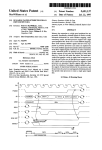
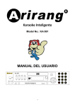
Figure
8
depicts the logical structure of the E-machine. After some deliberation, a
stack-based architecture was chosen over other possibilities
inherent
simplicity.
As can be
seen,
however,
for its
there are a number of
components not found in real stack—based computers.
31
Label
Registers
Label
Stacks
Variable
Registers
Variable
Stacks
CPU
Evaluation
Stack
Register
Evaluation
Stack
Program
Counter
Pl Cd
QPrevious
Program
Counter
Return
Address
Stack
Register
Return
Address
Stack
Save
Stack
Register
Save
Stack
Q-
Figure 8
The E -machine
32
Program memory will
executed by the E-machine.
contain
the
E—code
program
currently
being
The program counter will contain the address in
program memory of the current E-code instruction to be executed.
The
previous program counter, needed for backup purposes, will contain the
address
in
instruction.
program
memory
of
the
most
recently
executed
E-code
The line number register will contain the line number of the
high level language program statement corresponding to the group of E-code
instructions currently being executed.
The line number will be needed by
the dynamic display interface to highlight the current high level source
program line being executed.
The variable registers are an unbounded number of registers that will
be assigned to source program variables, constants, and parameters during
compilation from the source program into E-code. Each identifier name
representing memory in the source program will be assigned one variable
register in the E-machine.
As one can see in Figure 8, the variable
registers only contain pointers to individual variable stacks, which in
turn contain pointers into data memory, where the actual variable values
''
''
J
.
are stored. The reason for this complex arrangement will become clearer as
variables are discussed more thoroughly below.
The label registers are another unique component of the E-machine
fsguired for backup. There are also an unbounded number of these registers
and,
as described later, they are used to keep track of E-code label
•
instructions in an E-code program for backup purposes. Each E-code label
statement will be assigned a unique label register at compile time. A label
register, in turn, points to a label stack that essentially maintains a
history of previous instructions that caused a branch to this label.
33
The index register is found in real computers and serves the same
purpose
in the E-machine.
Under normal
circumstances,
the data in a
variable is accessed through the appropriate variable register.
However,
in the case of high level data structures, such as arrays and records, the
address of an individual data value is not at the memory location directly
accessible through a variable register.
Rather, it is stored at a location
offset from this memory location. When necessary, an offset value can be
'
T
placed in the index register and the E—machine can then access the proper
memory
location
as
required,
(by an addressing mode
called
register—
indexed) .
The evaluation stack pointer is also found in real computers. The
evaluation stack pointer keeps track of the top of the evaluation stack.
The evaluation stack is where the results of all arithmetic and logical
operations and assignments are maintained.
For example, in an arithmetic
operation, the operands are pushed onto the stack and the operation is then
performed on them.
The operands are consumed by the operation and the
result is pushed onto the top of the stack.
Assignments are performed by
popping the top value of the evaluation stack and placing it into a
variable. The advantages of a stack architecture are well known; several
popular computers use this design.
The return address stack pointer is a mechanism for implementing
procedure
and
function
calls.
When
a call
is
made
to
an
E-machine
subroutine, the program counter plus one is pushed onto the return address
stack.
Then,
when
the
E—machine
executes
a
return
from
subroutine
instruction, all it has to do is load the program counter with the top of
the return address stack.
34
The save stack pointer is used to store information required for
backup, which would otherwise be l o s t . Whenever some critical information
(as determined by the execution of a critical instruction) is about to be
destroyed, the required information is pushed onto the save stack.
This
ensures that when backing up, the instruction that most recently destroyed
some critical information can be reversed by retrieving that critical
information from the top of the save stack.
Finally, data memory represents the usual random access memory found
on real computers, but in the E-machine it is only used for holding data
values.
In real machines, a similar situation exists in some systems which
provide for separate code and data segments in m e m o r y . On the E-machine,
there is no bound to the available memory (or any of the stack m emory ) .
Implementations on real computers will naturally enforce some bounds, but
for the academic (small program) environment envisioned for this system,
no practical problems are expected to be encountered due to limited memory.
E-machine Instruction Set
The E-machine's instruction set is a quite small but complete set of
instructions; these instructions allow an E—code program to access data
easily and simply.
All arithmetic, logical, and assignment operations
occur on the evaluation stack.
variable registers.
Data is stored and recalled using the
All operations for backing up occur with a minimum of
information from the E-code program in question (in general, all the E-code
program has to do is use the correct form of the instruction— critical or
noncritical— to ensure that backing up can occur correctly) .
35
Addressing Modes
In
this
section,
the
various
addressing modes
available
to
the
E-machine instruction set are given.
variable mode - V# :
[variable register #~|—> [top of variable stack"!—> ldatal
This mode accesses the data at the memory location given in the top
element of the variable stack pointed to by variable register #.
constant mode - # :
m
This mode is often called the immediate mode in other architectures; #
is itself the integer, real, boolean, character, or address constant
operand required in the instruction. Also, there are some defined
constants. INTEGER, REAL, BOOLEAN, CHARACTER, and ADDRESS are the
size in bytes of an integer, real, boolean, character, and address
variable, respectively.
register mode - R# ;
[variable register #
> |top of variable stack!
This mode accesses the address at the top of the variable stack pointed
to by variable register #. This address is the location in data memory
of the current instance of variable #.
register indirect - R#+IR :
variable register # |-» [top of variable stack + IR |—>|data|
This mode accesses the data at the memory location at the top of the
variable stack pointed to by the variable register # plus the offset
stored in the index register. This is the addressing method used to
access array elements, record items, and elements of other high level
data structures.
variable indirect - V#+IR :
[variable register # |—> |top of variable stack |—>
!memory location + IR 1-» |data|
This mode accesses the data at the memory location stored at the memory
location at the top of the variable stack pointed to by variable
36
register # plus the offset stored in the index register. This is the
method used to implement high level language pointer variables.
Index Register - I R :
COD
This mode accesses the value in the index register directly. This is
the only register which acts like a standard, normal machines. It
should only be used in conjunction with the indirect addressing modes
above.
Instruction Set
This section lists all of the instructions in the instruction set of
the E-machine.
The argument ADDR refers to any addressing mode listed in
r. .
■'
e
v
. , ..
the last section. The argument TYPE refers to any of the data types
integer, real, boolean, char, and address; most instructions require that
the type of data being operated upon be specified.
The # refers to. an
integer constant. This differs from the constant mode described above in
that this # is used only to specify the number of an E-code label or an Emachine
variable
register.
The MODE
argument
determines
whether the
instruction is to be treated as critical or noncritical. The exact method
^or replacing the ADDR, TYPE, and MODE designators is unspecified and will
b® left up to the designer of the E—machine emulator. Backing up through a
noncritical instruction often still requires that something be pushed onto
the evaluation stack to keep the stack of the proper size;
arbitrary dummy value is used)
push ADDR, TYPE ;
Forward :
Pushes the value in ADDR onto the evaluation stack.
in such cases an
37
Backward :
Fops the top value of the evaluation stack and stores it in A D D R .
pop MODE, ADDR, TYPE :
Forward-Critical :
Pushes the value in ADDR onto the save stack and then pops the top
value of the evaluation and stores it in ADDR.
Forward-Noncritical :
Pops the top value of the evaluation stack and stores it in ADDR.
Backward-Critical :
Pushes the value in ADDR onto the evaluation stack and then pops
the top value of the save stack and places it in ADDR.
Backward-Noncritical :
Pushes the value in ADDR onto the evaluation stack.
add MODE, TYPE :
Forward-Critical :
Pops the top two values of the evaluation stack, pushes them onto
the save stack, and then pushes their sum onto the evaluation
stack.
Forward-Noncritical :
Pops the top two values of the evaluation stack and pushes their
sum onto the evaluation stack.
Backward-Critical :
Pops the top value of the evaluation stack and discards the value.
Pops the top two elements of the save stack and pushes them onto
the evaluation stack.
Backward-Noncritical :
Pushes a O onto the evaluation stack.
sub MODE, TYPE :
Forward-Critical :
Pops the top two values of the evaluation stack, pushes the two
values onto the save stack, and then pushes the bottom value minus
the top value onto the evaluation stack.
Forward-Noncritical :
Pops the top two values of the evaluation stack, and pushes the
bottom value minus the top value onto the evaluation stack.
Backward-Critical :
Pops the top value of the evaluation stack and discards it. Pops
the top two values of the save stack and pushes them onto the .
evaluation stack.
Backward-Noncritical :
Pushes a O onto the evaluation stack.
38
mult MODE, TYPE :
Forward-Critical :
Pops the top two values of the evaluation stack, pushes the two
values onto the save stack, and then pushes their product onto the
evaluation stack.
Forward-Noncritical :
Pops the top two values of the evaluation stack and pushes their
product onto the evaluation stack.
Backward-Critical :
Pops the top value of the evaluation stack and discards it. Pops
the top two values of the save stack and pushes them onto the
evaluation stack.
Backward-Noncritical :
Pushes a O onto the evaluation stack.
div MODE, TYPE :
Forward-Critical :
Pops the top two values of the evaluation stack, pushes the two
values onto the save stack, and pushes the bottom value divided by
the top value onto the evaluation stack.
Forward-Noncritical :
Pops the top two values of the evaluation stack and pushes the
bottom value divided by the top value onto the evaluation stack.
Backward-Critical :
Pops the top value of the evaluation stack and discards it. Pops
the top two values of the save stack and pushes them onto the
evaluation stack.
Backward-Noncritical :
Pushes a O onto the evaluation stack.
neg TYPE :
Forward :
Pops the top of the evaluation stack and pushes the negation of
that value onto the evaluation stack.
Backward :
Pops the top of the evaluation stack and pushes the negation of
that value onto the evaluation stack.
mod MODE, TYPE :
Forward-Critical :
Pops the top two values of the evaluation stack, pushes the two
values onto the save stack, and then pushes the bottom value modulo
the top value onto the evaluation stack.
39
Forward-Noncritical :
Pops the top two values of the evaluation stack and pushes the
bottom value modulo the top value onto the evaluation stack.
Backward-Critical :
Pops the top value of the evaluation stack and discards it. Pops
the top two values of the save stack and pushes them onto the
evaluation stack.
Backward-Noncritical ;
Pushs a O onto the evaluation stack.
line # :
Forward :
„
Loads the line number register with #, then the machine returns
control to the dynamic interface and enters a wait state.
Backward :
Loads the line number register with #, then the machine returns
control to the dynamic interface and enters a wait state.
cast TYPE, TYPE :
Forward :
Pops the top value of the evaluation stack, transforms the value
from the first TYPE to the second, then pushes the value onto the
evaluation stack.
Backward :
Pops the top value of the evaluation stack, transforms the value
from the second TYPE to the first, then pushes the value onto the
evaluation stack.
cmp MODE, TYPE :
Forward-Critical :
Pops the top two values of the evaluation stack, pushes the two
values onto the save stack, compares the bottom value with the top
value and then pushes the result of the comparison onto the
evaluation stack (i.e., one of LESS, EQ, and GREATER is pushed) .
Forward-Noncritical :
Pops the top two values of the evaluation stack, compares the
bottom value with the top value and then pushes the result of the
comparison onto the evaluation stack (i.e., one of LESS, EQ, and
GREATER is pushed).
Backward-Critical :
Pops the top value of the evaluation stack and discards it. Pops
the top two values of the save stack and pushes them onto the
evaluation stack.
40
Backward-Noncritical s
Pops the top value of the evaluation stack and discards i t . Pushes
two 0's onto the evaluation stack.
label MODE, #:
Forward-Critical :
Pushes the previous program counter onto the stack pointed to by
label register #.
Forward-Noncritical :
No operation.
Backward-Critical :
Pops the top value of the stack pointed to by label register # and
places it in the program counter.
Backward-Noncritical :
No operation.
br #:
Forward :
Load the program
instruction.
counter
with
the
address
of
the
label
#
Backward :
No operation.
beql, bneql, bless, bleql, bgtr, bgeql MODE, #:
Forward-Critical :
Pops the top value of the evaluation stack and pushes it onto the
save stack. If the value satisfies the conditional on the branch,
load the program counter with the address of the label #
instruction.
Forward-Noncritical :
Pops the top value of the evaluation stack. If the value satisfies
the conditional on the branch, loads the program counter with the
address of the label # instruction.
Backward-Critical :
Pops the top value of the
evaluation stack.
save
stack and pushes
Backward-Noncritical :
Pushes EQUAL onto the evaluation stack.
it onto the
41
call # :
Forward :
Pushes the current program counter onto the return address stack,
then loads the address of the label # instruction into the program
counter.
Backward :
No operation.
return :
Forward :
Pops the top value of the return address stack and loads it into
the program counter.
Backward : '
No operation.
alloc # :
Forward-Critical :
Pops the top value of the evaluation stack, pushes the value onto
the save stack, pushes the address of a chunk of free memory of
that size onto the variable stack pointed to by variable register
#.
Forward-Noncritical :
Pops the top value of the evaluation stack, pushes the address of a
chunk of free memory of that size onto the variable stack pointed
to by variable register #.
Backward-Critical :
Pops the top value of the variable stack pointed to by variable
register # and frees the memory allocated, pops the top value of
the save stack and pushes it onto the evaluation stack.
Backward-Noncritical :
Pops the top value of the variable stack pointed to by variable
register # and frees the memory allocated. Pushes a O onto the
evaluation stack.
link # :
Forward :
Pops the top value of the evaluation stack and pushes it onto the
variable stack pointed to by variable register #.
Backward :
Pops the top value of the variable stack pointed to by variable
register # and pushes it onto the evaluation stack.
42
unlink # :
Forward :
Pops the top value of the variable stack pointed to by variable
register # and pushes it onto the save stack.
Backward :
,,
Pops the top value of the save stack and pushes
variable stack pointed to by variable register #.
it onto the
Source Program Variable Representation
in E-machine Code
Understanding how the E-machine provides for the implementation of
high
level
source
language
variables
is
vital
to
understanding
operation of the E-machine, especially in backing up.
the
(In this context,
the term variable refers to any identifier in the source program that
requires memory, such as variables, constants, and parameters.) First, a
compiler that
generates
E-code translations
of,
say,
Pascal programs
assigns each variable in the Pascal program a unique E-machine variable
register. This is done statically at compile time, so that every variable
is associated with a unique variable register for the duration of program
execution, regardless of whether that variable is currently active or not.
The variable register for a variable does not contain the value of the
variable.
Rather, it contains a pointer to a unique variable stack for that
variable (look at Figure 8 again) . Since each variable register is really
only a pointer, it will be the same size regardless of whether the variable
is a simple variable or, for example, an array.
The variable stack pointed to by a variable register also does not
contain the value of the variable.
In this case,
each element of the
43
variable stack is itself a pointer to the actual variable value in data
m e m o r y . The stack is necessary because a particular variable may have
m u Itiple associated instances. Consider the case of a variable A that is
local to a recursive Pascal procedure. Each new recursive call to that
procedure would require that a new data memory location be set aside for new
instance of A. A' s variable register would point to A' s variable stack, and
the top of A' s variable stack would point to the value of the current
instance of A in data m e m o r y . The second stack element would point to the
previous instance of A in data memory, and so on. Most variables are not in
recursive procedures and thus will only have at most one instance during
Program execution.
In such cases, the variable register would point to a
variable stack that is just one element d e e p . The case for a variable A
with just a single instance is illustrated in Figure 9. Figure 10 shows the
situation of a variable A having three instance as the result of three
recursive calls to a procedure.
variable
registers
variable
stack
data
memory
•
•
•
.
•
•
•
•
□ -- 5C3-- 503
•
•
•
•
A
•
•
•
•
A's
stack
•
•
•
•
A'3
data
Figure 9
E-machine Global Variable Implementation
44
Whenever
a procedure or function exits,
the compiled E-code will
ensure that local variable instances are properly removed from data memory
by simply causing the top of the variable stacks to be popped for each
affected variable.
If a variable is totally deactivated as a result, its
variable register will simply point to an empty variable stack.
variable
registers
variable
stack
data
memory
stack
data
Figure 10
E-machine Recursive Variable Implementation
Notice that arrays and records can be handled in the usual fashion,
using offsets
(in the index register)
from the first location for the
variable in data memory to arrive at individual elements.
The Save Stack
To see how backing up is accomplished with this method of representing
variables, the role of the save stack must be explained.
The first thing to
45
consider is the kinds of information associated with a variable. There are
two kinds:
the location of the variable's memory and the data in the
variable's memory location. Both are subject to destruction or loss during
normal program execution.
It is easier to see how the second type of
information, the data, can be destroyed.
into
a variable,
destroyed.
the
Therefore,
old data
in
Whenever an assignment is made
the variable's memory
location
is
in order to restore the E—machine's state to the
state prior to the assignment, it is necessary to save the old data. This is
done on the save stack.
Upon backing up, the old variable value can then be
restored by retrieving it from the save stack.
Now consider the case of a memory location.
Recall that the data
memory location of a variable is kept in the stack corresponding to that
variable.
In the case, say, of a Pascal global variable, the single stack
element for that variable continues to point to the proper data memory
location for that variable throughout the execution of the program.
case
of
a variable
(again,
this
refers
to both
In the
local variables
and
parameters) in a procedure or function, however, the data memory location,
and hence the pointer to this location on the variable stack, may change
with each call.
That is, each time a call to the procedure or function is
made, a different data memory location may be allocated for the value of the
variable and pushed onto the top of that variable's stack; upon return from
the procedure or function, that address will be popped off the variable's
stack as the variable is deallocated.
At this point, information critical
to backup would be lost if the address popped off were not saved in some
way.
46
This is where the save stack comes in.
Whenever any information is
about to be lost in one of the above fashions, the information instead is
pushed onto the save stack.
Figure 11 shows the initial variable register,
variable stack, and data memory location for a variable X. Also included is
the save stack.
variable
registers
variable
stack
data
memory
X's
X rS
stack
data
save
stack
LZf
X
Figure 11
Variable and Save Stack for a Variable X
Notice that the save stack is empty now.
(Technically, this situation
could not arise since X has a value at this point, and therefore at some
point in the past must have had an assignment statement performed upon it
which would have required the old value to be pushed onto the save stack.
For purposes of this example, we will ignore this fact.)
Now, let's perform
an assignment operation:
X - 27
The effect this will have upon the E—machine's structures is shown in
Figure 12. Notice that the top of the save stack now contains the old value
X and that the new value of X is stored in the old memory location. In
47
this case, the information which would have been destroyed was the data,
not the memory location.
variable
registers
variable
stack
-5C
data
memory
save
stack
-^TTT
x's
x's
stack
data
Figure 12
Variable and Save Stack After Assignment to X
order to back up at this point, all that would be necessary would be
to pop the top of the save stack and place the popped value into the memory
location pointed to by the top of X' a variable stack. This procedure allows
any assignment to be reversed.
Preparing for the reverse execution of statements that lose location
information is somewhat more involved.
To understand this task better,
recall from the previous section how the E—machine architecture provides
for the implementation of high level language variables (remember, too,
that the term variable is used here to stand for any high level language
identifier requiring memory,
such as actual variables, parameters, and
constants). Each variable has a permanently assigned variable register.
Each variable register points to a unique,
associated variable stack.
48
Each element of the variable stack is a pointer to an instance of the
variable value in data memory; the top of the variable stack points to the
current, active instance of the variable.
Thus, since the location of a variable's assigned variable register
remains constant throughout program execution, and this variable register
always points to the current top element of the associated variable stack,
the only location information that can be lost during normal forward
execution is the
location of a variable's value
in data memory as a
procedure or function is exited (i.e., the value on top of the variable
stack for the variable) . Thus, upon exit of a procedure or function, when
the values of local variables
(including parameters and constants) and
their locations in data memory are normally lost, the locations of these
variables, must be saved on the save stack.
procedure or function call,
When backing up through a
(i.e. executing the procedure or function in
reverse) , the original locations of the local variables in data memory can
be restored to the top of their respective variable stacks from the save
stack.
How can one be certain that the original variable values will be in the
restored locations upon backing up? Consider how a value in data memory is
changed.
The only way this can happen is through an assignment operation.
But earlier in this chapter, a mechanism was introduced that allowed an
assignment instruction to be reversed.
location may
have
been
Therefore, even though a memory
assigned numerous
different values
since the
procedure exited, as backing up occurs, that memory location will have been
reset to the required value by the time the procedure is encountered in
reverse.
49
Consider the example Pascal program fragment in Figure 13. It consists
of a header definition for procedure something with one value parameter;
there are three calls to that procedure from another routine.
The lines
labeled 0,1,2, and 3 have corresponding sections in Figure 14.
Figure 14
contains the variable structures and the save stack that correspond to each
of the procedure calls in Figure 13.
The section labeled 0 in Figure 14
refers to the state of the structures before any procedure call has been
executed.
Notice that the save stack is empty, and notice too that the
variable stack for P is also empty.
Procedure something(P : integer);
0
1
2
3
something(7);
something(5);
something(-16);
Figure 13
A Pascal Procedure Fragment something
Now let's examine line I in Figure 13.
This is the first call to
procedure something. Notice that during the call, P's stack in section I of
Figure 14 now has a value, I, which is a location in data memory.
also that the data memory location which this points to
location
I)
contains
Notice
(data memory
the value of the parameter which was passed to
something. During this call, any references to P are referring to the data
memory location that is pointed by the top of P's variable stack.
50
Variable structures
During Procedure Call
variable
registers
variable
stack
Save stack after
Procedure call
data
memory
0 C3— SC3
*
save
stack
Q
.
□ — 3tZ3—
2
—
K
7
I
n
L-1-- 41--- ^EH]
3
-
-
'■■■'
•
'
•
•
•
•
•
P
■
.
.
.
:
P'9
stack
4
T
I
.
P'S
data
save
stack
Figure 14
Variable and Save Stack During Successive
Th. .... ataolt i„ ,.ction I of Figu,, U
Calls to Procedure something
,ho., th« , f t . of th« ,t.ok
.ft.r p.oo.dur. ,onething fini.h., ...outing for th. fir.t tin,.
that it no. h,, th, value I on top.
Notic
Thi, i, b.c,u,. .h.n th. proo.dur.
..it.d, th. d.t. ...cry location to .hioh P ... pointing .ould hav. been
51
lost,
so it was
saved by the E-machine on the top of the save stack.
Consider now the second call to something in line 2 of Figure 13 and compare
it with section 2 in Figure 14.
Th. top O f P ' , v.ri.bl. =t.=k now contain, th. .,In, 7, which point, to
d,t. memory location 7, which contain, a 5.
No- any
. . . . . . to P will
r.f.r to memory location 7 (i..., to th. ,.in. 5) . wh.n procedure ,Ometting
ia e.ited thi, time, th. top of th. v.riabl. ,tack would again b. lost if it
».r. not saved.
onto
th.
save
Thu,, th, 7 on top of th. v.riabl. stack for P i, pushed
,tack
by
th.
E-machine,
resulting
in
th. .
,tack
configuration of section 2 in Figure 14.
The third call to procedure something follows in exactly the same
manner.
When the procedure is executing, the variable P refers to the data
memory location contained on the top of P's variable stack, and when the
procedure ends, that data memory address is pushed onto the save stack.
Reversing through these procedure calls simply consists of popping the
addresses off the save stack and pushing them onto P's variable stack when
reversing through the procedure's exit, and popping the top of P's variable
stack when reversing through the procedure's entrance.
The Label Registers
Execution in a program I, not a Slmpl., linear affair.
There ar,
branch.,, call, to subroutines, return, from subroutine,, and other non
sequential type, of instruction, that add complexity to th. problem of
backing up.
We have seen ho. to t,v.r,e many E-machin. instruction, by
52
utilizing the save stack.
What we haven't yet determined is how to reset
the-current program counter so that it points to the proper previous
instruction.
If
the
current
instruction
was
arrived
at
from
some
instruction other than the immediately preceding instruction (e.g., via a
branch instruction) there must be some method available for recovering the
line number of the instruction branched from.
For example. Figure 15 gives a simple E—code program (for clarity,
variables are referred to by name rather than their variable registers, and
addressing modes, data types, and critical and noncritical designators
have been omitted) . The program does the following: I '3 value is pushed
onto the evaluation stack followed by J's value.
The cmp instruction of
line 3 then compares the top two stack values, consuming these values, and
pushing the result of the comparison onto the stack. Notice line 4; if the
top of stack value denotes "equal", a branch must be made to the label I
instruction, which is in line 7 (that is, the current program counter must
be set to 7) . Otherwise execution proceeds sequentially through lines 5
and 6 until line 7 is reached.
The label instruction of line 7 is the interesting instruction in this
case. As seen, depending on the values of I and J, the instruction executed
just previous to line 7 could have been either line 4 or 6.
How can it be
determined for backing up which one really did precede line 7?
The brute force method of solving this problem is simple but very
inefficient. If, at each step, the current program counter is stored on a
stack,
all that is needed to restore the current program counter upon
backing up is to replace its value with the top of stack value.
This method
53
I
2
3
4
5
6
7
8
push
push
cmp
breq
push
pop
label
halt
I
J
I
I
J
I
Figure 15
Simple E-code Program With a Branch
will
work,
but
it
is
inefficient
for
the
following
reason.
Most
instructions in a program have only one possible previous instruction, the
one that directly precedes it in the program.
In the example of Figure 15,
only line 7 has more than one possible previous instruction.
other instructions have only one.
All of the
A more elegant and efficient method to
solving this problem, then, is to identify the instructions with more than
one possible previous instruction
points")
(referred to hereinafter as "branch
and only save the previous program counter when one of these
instructions is executed in the forward direction.
In order to do this,
branch point instructions must be identifiable.
How can branch points be identified by the E-machine as it executes an
E-code
program?
The
characteristics
of
a
branch
point
are
easy
to
categorise. A branch point is any instruction that can be executed in some
order other than sequentially from the Instruction immediately preceding
it.
Most such instructions can be readily identified:
since both branch
and call instructions require a label as one of their arguments,
any
instruction that is a branch point because of a branch or call must be an
E-code label instruction.
This leaves one class of branch points still
unidentified, those arrived at by a return from a procedure or function.
54
The return instruction does not--and indeed cannot— have a label as an
argument; instead, control must be returned to the instruction immediately
following the call that invoked the procedure or function (the utility of a
procedure or function lies in the fact that it can be called from anywhere
and, after execution, will return to the instruction immediately after the
call).
From the above discussion, it is clear that each E-code instruction
that immediately follows a procedure or function call is a branch point.
However, examining an arbitrary E-code instruction in isolation does not
allow one to determine whether the previous instruction was a call.
Thus,
some sort of mechanism must be employed to mark such an instruction as a
branch point at compile t i m e . Since all branch points except those arrived
at by a return are E-code label instructions in any case, the same technique
can be employed to branch points arrived at by a return.
The compiler can
simply be designed to generate an E-code label instruction immediately
following each procedure or function call.
This
technique
instructions.
ensures
that
all
branch
points
are
E-code
label
Thus, for successful backup, when the E-machine executes a
label instruction in the forward direction,
program counter value in some fashion.
it must save the previous
Recall that in the E-machine, the
previous program counter is always maintained in the register by that name.
Every time the current program counter is changed, its old value is first
placed into the previous program counter.
not a stack.
(Notice that this structure is
Only one value is stored at any one time in the previous
program counter.)
55
In order to save the previous program counter for successful backup,
then,
whenever an E-code label instruction is executed, the E-machine
employs its label stacks and label registers (see Figure 8).
Each label
instruction is to be assigned a label register at compile time, where each
label register is a pointer to a unique label stack (the reason for the
stack is given later) . Thus whenever a label instruction is encountered by
the E-machine, the value in the previous program counter is pushed onto the
stack referenced by that label's register.
Now, look at the example program given in Figure 16.
There are two
branch points in this program: line I and line 11. This program contains a
loop in which lines I through 10 are executed until I and J are equal.
Obviously, this loop could iterate a large number of times, and each time
the label instruction of line I is executed, it appears that the previous
program counter should be pushed onto the label stack of label I. However,
except for the very first time line I is executed, the previous program
counter will always contain 10. There should be a way to take advantage of
this repetition and save some space.
The E-machine does this in the following way.
Each element of the
label stack associated with each branch point has two parts,
one for
holding the value of the previous program counter and one for holding a
count, as shown in Figure 17. Rather than just pushing the previous program
counter onto the label stack when a label instruction is executed by the
E-machine, the E-machine first compares the previous program counter to
the number stored in the top element of the label stack.
values
are
equal,
the
associated
counter
on
the
If these two
stack
is
simply
incremented, thus recording the number of times this label instruction was
56
reached from the same previous instruction.
Thus, rather than storing n
identical previous program counter values, where n is the number of times
the loop is iterated,
only one copy of the repeated previous program
counter value is saved along with n, a tremendous savings.
0
I
2
3
4
5
6
7
8
9
10
11
12
• e #
label
push
push
cmp
breq
push
push
add
pop
br
label
halt
I
I
J
2
I
I
I .
I
2
,
-
Figure 16
Simple E-code Program with a Loop
Address
Address
Address
Address
Counter
Counter
Counter
Counter
Figure 17
General Label Stack
Look again at Figure 16 and consider what will happen to the label
stack
for
the
"executes the
branch
point
instructions.
instruction
at
Assume
I equals
that
line
I
as
the
E-machine
3 and J equals
5.
The E—machine will step sequentially through the instructions starting
57
at
0.
When
first time,
it
(at
this
the
label I instruction at line
I is
executed
for the
the address of the the instruction executed just prior to
point,
instruction
0)
is
pushed
onto
label
V s
label
stack, resulting in the label stack of Figure 18.
0
I
Figure 18
Label Stack After 0 Loop Iterations
As the E-machine continues executing, I and J will be compared, they
be found to be not equal and so the E—machine will continue executing
sequentially, incrementing I in the process, until line 10 is reached.
At
that point, a branch to the label I instruction is executed, which loads I
into the program counter.
When the label I instruction is executed, the
address of the instruction that was executed just prior to this is pushed
onto label Ir s stack.
Since that instruction was the branch instruction at
line 10, a 10 must be pushed as shown in Figure 19.
At this point in the execution, the loop has executed once, I equals 4,
J equals
5,
and the
E—machine
has
just
executed
line
I.
Proceeding
sequentially with the execution of the program results in I and J being
compared.
Once again,
I does not equal J and the E—machine executes
sequentially, again incrementing I, until line 10 is reached.
point, the branch to label I is executed.
At this
The execution of label I causes
the address of the instruction executed just prior to the label I, 10, to be
58
pushed onto label Irs stack.
This results in the label stack of Figure 20.
Notice that no new address was actually pushed onto the stack.
Since the
top of the stack had the same value as the value that was to be pushed, the
counter of the top of the stack was simply incremented (from I to 2) . If the
address had been different than the value of the top of the stack, a new
value and counter would have been pushed onto the top of the stack.
10
I
0
I
Figure 19
Label Stack After I Loop Iteration
10
0
2
I
Figure 20
Label Stack After 2 Loop Iterations
How to reverse through a label instruction should now be clear.
The
address on top of that label's stack is simply placed in the program
counter.
If the corresponding count is one, the label stack is also popped,
otherwise the count is just decremented.
59
Critical vs. Noncritical Instruct ions
Early on in the chapter,
backwards
and
a
high
it was mentioned that a machine running
level
language
program
represented similar but not identical processes.
executing
backwards
The reason this is so is
that one high level language statement will, in general, correspond to many
machine
language
instructions.
For
example,
the
Pascal
assignment
statement
Y
X + Y - 17 * Z * Z;
*111 be translated into at least ten machine language instructions,
as
shown in Figure 21, only one of which has any effect on the values of the
variables in this statement (the final pop instruction) . Since the intent
of the proposed system is to display the execution dynamics of high level
language programs,
it is unnecessary to be concerned about precisely
backing
up the
E-code
instructions
that
values.
This observation led naturally to a classification system for
E-machine instructions that reflects this
only
calculate
situation.
intermediate
If an E-machine
instruction destroys information necessary for backup in the high level
language program, it is classified as critical by the compiler; if it does
not, it is classified as noncritical.
This
identification of E— code instructions
as either critical
or
noncritical allows the E-machine to save for backup purposes only that
information necessary to reverse statements in the high level language
program.
Since the vast majority of compiled E—code instructions will be
noncritical,
a large
savings
in storage
space and time
is realized.
60
However, it should be noted that the flexibility is present to accurately
back up E-machine code line by line by simply designating each instruction
as critical.
push
push
push
push
mult
push
mult
sub
add
pop
X
Y
17
Z
Z
Y
Figure 21
E-code Translation of X
X + Y - 17 * Z * Z;
61
CHAPTER 6
COMPILING TO E-CODE
The
actual design of a compiler
programming
language
(e.g.,
Pascal)
for translating
into
E-code;
as
some
high
level
as
other
well
applications for the E-machine, is left for othe r s . However, this chapter
is included as a starting point to assist those who will be developing
compilers for the E-machine.
The following description is only a guide to
the most important considerations facing a compiler writer and is not meant
to be complete.
Recall that the purpose of the E-machine is to allow high level
programming language execution dynamics to be displayed dynamically as an
aid to teaching and learning programming.
Therefore, when the dynamic
display interface is to show a high level language program executing, both
the high level language source program and the compiled E-code program must
both be available.
Only the E-code program will be executing.
the
appear
user
it must
executing.
as
if the
high level
language
However, to
program were
This can be accomplished using two E-machine components: the
line number register and the variable registers.
Recall from Chapter 5 that the line number register contains the line
number of the source program statement that was translated into the E-code
instruction
group
that
is
currently
executing.
The
dynamic
display
interface will use the information in this register to indicate to the user
which
source
program
statement
in
his
or
her
program is
executing.
62
Generating E-code
instructions
that
correctly update the line number
register is one of the most important parts of an E-code compiler.
The variable registers are the second component of the E-machine that
will be used by the dynamic display interface in showing source program
execution.
Recall that each variable (that is, each variable, parameter,
and constant)
of the source program will be assigned a unique variable
register at compile time.
Since it will be necessary for the dynamic
display interface to update the values of any variables that have changed
with each statement execution in the source program, it is essential that
the dynamic display interface have access to a symbol table that associates
each variable in the source program with its unique variable register.
The
symbol will allow the dynamic display interface to ascertain the value of
each variable and update the display of variable values.
The creation of
this symbol table is another important task of an E-code compiler.
Recall from Chapter 5 that many E-code instructions have two m o d e s :
critical
and
noncritical.
An
E-code
compiler
must
decide
during
translation whether a given E-code instruction should be used in critical
or in noncritical mode.
This decision will perhaps be the most compiles
part of designing an E-code compiler,
later in this chapter, an ad hoc
method for doing this is presented.
First, let's look at one possible method of building the symbol table,
a straightforward t a s k . Consider the Pascal program in Figure 22. A simple
way to generate a symbol table for this program is just to start at the
beginning of the program and scan one line at a t i m e . Each time a variable
declaration is encountered
(again, this is the extended definition of
variable), assign the next available E-machine variable register to that
63
variable. When the last line of the program is reached,
variable will have been assigned a variable register.
each program
This would take only
a single pass through the source program. The symbol table in Figure 23 was
generated in this way from the Pascal program in Figure 22.
Notice in
Figure 23 the method used for tagging parameters with the procedure or
function to which they belong. This same method could be used to tag local
variables.
1
program recurse
(input,output);
2
3
4
5
var
6
function factorial(n : integer)
ct,n,sum : integer;
: integer;
7
8
9
10
11
12
13
14
15
16
17
18
19
20
21
22
23
24
25
26
27
28
29
30
31
begin
if n — 0
then
factorial
else
factorial
end;
I
n * factorial(n-1)
procedure increment(var x : integer);
begin
x
end;
x + I
begin
sum :— 0;
n
I;
while n < 4 do
if sum < 10
then begin
sum :■ sum + factorial(n);
increment(n)
end
end.
Figure 22
Example Pascal Program
64
Generating E-code instructions to update the line number register
and deciding
handled
whether
an
the
same
with
packetizing.
instruction
is
critical
technique.
This
or
not
can both be
technique
is
called
Packetizing is a method for dividing the source program
into a set of packets,
where each packet represents the smallest unit
of a source program to be highlighted by the dynamic display interface
as
execution
progresses.
dynamic
display
program
statement
languages,
Until
interface
being
a statement
would
now,
it
simply
executed.
has
been
highlight
However,
can be quite complex
in
assumed
the
current
typical
(e.g.,
that
the
source
high
level
an if statement).
A packet will represent smaller components of the source program that
need to
compiler
be
writer
highlighted
must
use
by
his
the
or
dynamic
her
display
knowledge
interface.
of
the
high
The
level
programming language to decide how to packetize that language. Then it
must
be determined in the E-code where
critical
instructions are to
occur in translation of packets and the types of critical instructions
to
employ.
packetized.
Figure
24
is
a
diagram
showing
Following the example of Figure
24,
how
Pascal
can
be
a packet is defined
as the smallest element a user of the dynamic display interface would
find
interesting.
This
is
a very
ad hoc definition,
but
it
should
help direct the efforts of a compiler writer, who obviously must work
in
close
interface.
collaboration
with
the
designer
of
the
dynamic
display
65
Name
Ct
n
Register
I
2
sum
3
4
factorials
increments
5
Figure 23
Symbol Table For Pascal Program
The
packetizing method
compilation as follows.
illustrated
in
Figure
24
can be
used
in
Take each packet in the diagram and write out
if and where critical instructions may occur in the translation of the
packet.
Figure
diagram
in
25
shows
Figure
the
24.
result
Notice
of
this
that
the
process
only
instructions are alloc, link, pop, and label.
a usable
heuristic
for identifying
critical
will occur,
fashion.
some
If
of
but
these
not
critical
instructions
E-code
is to make
This will ensure that
necessarily in the most
instructions
the
Since this is the case,
every instance of those instructions critical.
proper backup
applied to
were
designated
efficient
critical,
when, in fact, they could have been designated noncritical, this would
mean
some
stored.
information
Finding an
that
optimal
is
unnecessary
way to
generate
for
backing
code
up
is
for backing
being
up
is
beyond the scope of this thesis, however, and will be left for others.
66
[program name(input,output,files);]
[const]
[const declaration]
[type]
[type declaration]
[var]
[variable declaration]
[assignment statement]
[begin]
[end]
[procedure call]
[if (boolean expression)]
[then]
then clause
[else]
else clause
[case (expression) of]
[const : ] case body;
[end]
[repeat]
loop body
[until (boolean expression)]
[while (boolean expression)
loop body
do]
[for VAR :■ EXPR toldownto EXPR do]
loop body
[procedure name]
[(parameter declaration);]
procedure body
[function name]
[ (parameter declaration);type;]
function body
Figure 24
A d Hoc Packetizing Method for Pascal
67
There is still one unusual area of code generation that should be
mentioned:
how to generate the E-code instructions necessary to update the
(source program) line number register.
source program has been packetized.
This can be done easily once the
Whenever the compiler encounters a
left packet symbol, in this case, [, it can generate the command
line #
where # is the line number in the source program of the line that contains
this packet.
The line command generated by the left packet symbol can be
considered to be an E-machine interrupt:
it can have the effect of causing
control to be returned to the dynamic display interface just following the
execution
of the
E-machine
code
corresponding to the
current
source
program packet being executed, and just prior to the execution of the next
packet. When the dynamic display interface sends a signal to the E-machine
to resume, the E-code corresponding to the next packet of instructions can
be executed by the E-machine, and so.
A packetized version of the program of Figure 22 is given in Figure 26.
Figure 27 presents a possible in-line translation of the program of Figure
26.
The mode designator c is used for critical instructions and n for
noncritical
translation.
instructions.
interface.
are included to help
explain the
In the comments, PC refers to program counter and PPC to
previous program counter.
with Figure
Comments
23,
Figure 27 should also be viewed in conjunction
the associated
symbol table
for the
dynamic display
68
Program Packet
Critical Instructions
[program name(input,output,files);]
[const]
[const declaration]
none
none
none
[type]
[type declaration]
none
none
[var]
[variable declaration]
none
alloc #
[assignment statement]
pop
[begin]
V#
none
[end]
none
[procedure call]
none
[if (boolean expression)]
[then]
then clause
[else]
else clause
none
none
label #
label #
[case (expression) of]
[const : ] case body;
[end]
none
label #
label #
[repeat]
loop body
[until (boolean expression)]
[while (boolean expression)
loop body
(after the entire
if statement)
do]
label #
none
label #
(after the entire
repeat-until statement)
label #
label #
[for VAR
BXPR to downto BXPR do]
loop body
(after the entire
while statement)
label #
label #
(after the entire
for statement)
[procedure name]
[(parameter declaration);]
procedure body
none
alloc #/link #
[function name ]
[(parameter declaration)!type;]
function body
alloc #/link #
Figure 25
Packetizing and Determination of Critical Instructions
69
I
[program recurse
(Input,output);]
2
3
4
[var]
[ct], [n], [sum]
: [integer;]
5
6
[function factorial]([n ; integer]) : [integer;]
7
8
9
[begin]
[if n - 0]
10
[then]
11
[factorial
12
13
14
1]
[else]
[factorial
n * factorial(n-1)]
[end; ]
15
16
[procedure increment]([var x : integer]);
17
18
19
20
21
22
[begin]
[x
x + 1]
[end;]
[begin]
23
[sum
24
[n
25
[while n < 4 do]
26
[if sum < 10]
27
0;]
I;]
[then begin]
28
[sum
29
[increment(n)]
30
[end]
31
sum + factorial(n);]
[end. ]
Figure 26
Example Packetized Pascal Program
70
a
tv to
[program recurae
line
1
(input,output);]
(display should highlight line I)
(no B-code generated}
[var]
line 3
(display should highlight line 3}
[ct], [n], [sum] : integer;]
o> cn
line
push
alloc
line
push
alloc
line
push
4
(display should highlight line 4}
INTEGER,integer (push INTEGER onto evaluation stack)
c, I
(allocate top-of-stack bytes to variable 1}
4
(display should highlight line 4}
INTEGER,integer (push INTEGER onto evaluation stack}
c,2
(allocate top-of-stack bytes to variable 2}
4
(display should highlight line 4}
INTEGER,integer (push INTEGER onto evaluation stack)
alloc c,3
(allocate top-of-stack bytes to variable
[function
label
line
line
push
alloc
pop
factorial<[n : integer]) : integer;]
c, I
(push PPC onto label 1's stack)
6
(display should highlight line 6}
6
(display should highlight line 6}
INTEGER,integer (push INTEGER onto evaluation stack)
c,4
(allocate top-of-stack bytes to variable 4}
c,V4
(pop the top of the stack into variable 4}
7
8
10
11
[begin]
" line
8
(display should highlight line 8}
[if n - 0 ]
line
9
(display should highlight line 9}
push V4,integer
(push value in V4 onto the evaluation stack)
push
0,integer
(push 0 onto the evaluation stack)
cmp
n,integer
(compare top of stack to next lowest,}
(push result)
bneq n,2
(branch to label 2 if the condition is met)
[then]
line
10
(display should highlight line 10}
[factorial
1]
line
11
(display should highlight line 11)
push
!,integer
(push I onto the evaluation stack)
br
3
(branch to label 3}
[else]
label c, 2
(push PPC onto label 2's stack)
line
12
(display should highlight line 12}
Figure 27
Example In-Line E-code Translation of a Packetized Pascal Program
71
[factorial
n * factorial(n-1) ]
13
(display should highlight line
c,3
(push PPC onto label 3's stack)
V4,integer
(push v4 onto the evaluation stack)
V4,integer
(push v4 onto the evaluation stack)
I,integer
(push I onto the evaluation stack)
n,integer
(subtract top of stack from next down,)
(push result)
call
I
(call label associated with factorial)
label c, 4
(push PPC onto label 4's stack)
mult
n,integer
(multiply the top two values of the stack)
(push result)
[end;]
line
14
(display should highlight line 14)
unlink 4
(pop the top of 4's variable stack)
line
label
push
push
push
sub
return
15
16
17
18
21
22
(deactivate 4)
(pop top of the return address stack into the)
(program counter)
[procedure increment([var x : integer]);]
label c,5
(push PPC onto label 5's stack)
line
16
(display should highlight line 16)
line
16
(display should highlight line 16)
link c,5
(pop address from top of stack)
(push onto label 5's stack)
[begin]
line
18
(display should highlight line 18)
[x
* + 1]
line 19
(display should highlight line 19)
push V5,integer
(push V5 onto the evaluation stack)
push
!,integer
(push I onto the evaluation stack)
add
n,integer
(add top two values of stack)
(push the result)
pop
c,V5,integer(pop the top the the evaluation stack into V5)
[end;]
line
20
(display should highlight line 20)
unlink 5
(pop address off 5's label stack)
return
(pop top of the return address into the PC)
[begin]
line
[sum
22
0;]
(display should highlight line 22)
line 23
(display should highlight line 23)
push
0,integer
(push 0 onto the evaluation stack)
pop
c,V3,integer (pop the top of the stack into V3)
Figure 27
(continued)
72
24
[n sline
push
pop
25
[while
label
line
push
push
cmp
bgeq
26
27
28
29
30
31
I;]
24
(display should highlight line 2 4 J
I,integerjpush I onto the evaluation stack}
c,v2,integer (pop the top of the stack into V2)
n < 4 do]
6
(push PPC onto label 6's stack)
25
(display should highlight line 25)
V2,integer
(push V2 onto the evaluation stack)
4,integer
(push 4 onto the evaluation stack)
n,integer
(compare the top two values of the stack)
n, 7
(if the top of the stack matches the)
(condition, branch to label 7}
[if sum < 10]
line
26
(display should highlight line
push V3,integer
(push V3 onto the evaluation stack)
push 10,integer
(push 10 onto the evaluation stack)
cmp
n, integer
(compare top of stack to next down)
bgeq n, 8
(branch if the top of stack matches)
(the condition)
[then begin]
line 27
(display should highlight line
[sum
sum + factorial(n);]
line 28
(display should highlight line 27)
push V3,integer (push V3 onto the evaluation stack)
push V2,integer (push V2 onto the evaluation stack)
call
I
(call subroutine at label I)
label c,9
(push PPC onto label 9's stack)
add
n,integer
(add top two values of the evaluation stack)
[increment(n);]
line 29
(display should highlight line 29)
push R2,address (push V2's address onto the stack)
call
5
(call procedure increment)
[end]
stack)
(push PPC onto label 8's i
label c, 8
(display should highlight line 30)
line 30
(branch to label 6)
6
br
(push
address of PPC onto label 7's stack)
label c, 7
[end.]
line
halt
31
(display should highlight line 31)
(stop executing)
Figure 27 (continued)
The translation in Figure 27 provides the intuition for the way that
compiling a Pascal program to E-code should proceed.
A more rigorous
definition is beyond the scope of this thesis. The next chapter contains a
73
recap of some of the main points of this thesis and some new directions that
this project could take.
74
CHAPTER 7
CONCLUSIONS AND NEW DIRECTIONS
The
goal
of
this
thesis
was
the
design
of
a
virtual
machine
architecture to support research and development in the realm of dynamic
teaching
aids
for
introductory
beginning programming courses.
computer
science
courses,
primarily
Thus this virtual machine architecture was
to support the execution of high level language programs in a fashion that
made the display of all facets of program execution dynamics feasible and
flexible.
The
most
architecture
was
important
the
specification
requirement
for
for
the
reverse
virtual machine
execution.
This
specification arose from experience with DYNAMOD; a common request from
students viewing DYNAMOD examples in the classroom was for the instructor
to back up and repeat certain statements.
Thus was born the E-machine, a
virtual machine that appears to meet the goals of the thesis quite well.
Much remains to be done to realize the ultimate goal of a comprehensive
teaching and learning tool for introductory computer science. An emulator
the E-machine must be written, a dynamic display interface must be
designed
and
Furthermore,
compiler,
implemented,
at
must
least
be
and
a
user
one compiler,
written.
It
is
interface
for example,
proposed
that
must
be
developed.
a Pascal to E-code
the
emulator,
all
compilers, and both interfaces be implemented in C in order to ensure the
system's portability to virtually all computer types likely to be used by
75
students.
Once this has been accomplished,
the entire package can be
incorporated into a hypertext environment built around an online textbook.
If this looks like a never-ending project, it is!
Unlike a commercial
system that must support the production people who develop applications
with that system, and therefore cannot later incorporate radical changes
without disrupting the continued effective use of the system, the project
envisioned here will suffer no such constraints.
As a purely academic
system, it can be changed at will to incorporate pedagogical innovations
that support the mission.
Consider the E-machine itself.
As it stands, it should support the
execution of Pascal programs quite well, with one exception: no provision
has been made for handling input and output. This was a conscious omission
that leaves this portion of the design to those implementing the dynamic
display interface.
If it turns out that input and output is best handled by
the display interface, that will be fine. However, if it becomes clear that
new instructions need to be added to the E-machine instruction set to
support
input
and output,
that
will be
fine,
too.
Other
high
level
programming languages, if incorporated into this system, may also require
that new instructions be added to the instruction set of the E-machine.
A
good example of this would be the bit-level operations of C. The E-machine
was intended to be an open-ended project from the start.
In conclusion, it is hoped that the E-machine will not just sit on a
shelf and gather dust, but that it will soon be implemented and become a
part of the envisioned dynamic teaching and learning system.
every reason to believe that this will be the case.
There is
76
REFERENCES CITED
ALICE:The Personal Pascal. Looking Glass Software Limited, 124 King St. N.
Waterloo, ON, N2J2X8
Brown, M. H. 1988. Exploring Algorithms Using Balsa-II. COMPUTER,
21, no. 5, May 88, ppl4-36
vol.
Communications of the ACM 1988. Special issue on hypertext, vol. 31, no. 7,
Jul 88
Elsworth
E.
F.
1978.
Compilation via
an
intermediate
language.
The
Computer Journal, vol. 22, no.3, Aug 79, pp226-233
Hille R. F. and Higginbottom T. F . 1983. A System for Visible Execution of
Pascal Programs. The Australian Computer Journal, vol. 15, no. 2, May
83, pp76-77
Kornerup P., Kristensen B. B., and Madsen O. L . 1980. Interpretation and
Code Generation Based on Intermediate Languages. Software-Practice
and Experience, vol. 10, no. 8, Aug 80, pp635-658
Meng-Kawalek L. 1983. A Pascal Pedagogical System for the Conversational
Monitor System. Unpublished MS project. Computer Science Department,
Washington State University.
Ng C. 1982. Ling Users Guide. Unpublished MS project. Computer Science
Department, Washington State University.
------- . 1982. Ling Programmers Guide. Unpublished MS project. Computer
Science Department, Washington State University.
Nori K. V. et al.
1974. The Pascal <P> Compiler-Implementation Notes.
Berichte des Institute fur Informatik 10, Eidgenossiche Technische
Hochschule, Zurich.
Fountain D. 1989. The X Window System. BYTE, Jan. 89, 353-360.
Rezvani S. 1981. A Dynamic Library of Interactive Language Examples.
Unpublished MS project. Computer Science Department, Washington
University.
77
Ross R. J. 1980. A Microprocessor System for the Dynamic Presentation of
Programming Language Concepts. Grant from the Apple Education
Foundation
(Foundation for the Advancement of Computer Aided
Education), no. 441, 1980-1982.
_______ • 1981. L O PLE: A Dynamic Library of Programming Language Examples.
ACM SIGCUE Bulletin, 1981
_______ • 1982. Teaching Programming to the Deaf. ACM SIGCAPH Newsletter,
no. 30, Autumn 82, ppl8-24
_______ • 1983. A Dynamic Library of Programming Language Examples. Grant
from the National Science Foundation, SPE-8263156, SPE-832-0677.
_______ - 1988. DYNAMOD USER'S GUIDE Version 2.0 Release 1.1. Technical
Report 88-1, Computer Science Department, Montana State University.
Scheftic C. and Goldenson D. R. 1986. Teaching Programming Method and
Problem Solving; The Role of Programming Environments Based on
Structure Editors. Proceedings of the National Educational Computing
Conference, Jun. 1986.
SHARE Ad-hoc Committee on Universal Languages 1958. The Problem of
Programming Communication with Changing Machines:
A Proposed
Solution. Communications of the ACM, vol. I, no. 8.
Turbo Debugger 1988. 1800 Green Hills Road, Scotts Valley, CA; Borland
International.
User Manual for Dr. Pascal 1989. P. O. Box 7788, Princeton, NJ: Visible
Software.
rr^Tt UNrvmrry
1762 10177771
B1
B S e1Td
t o a /cmaim
.. ML
■