1
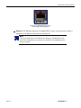
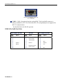
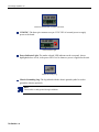
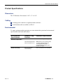
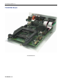
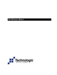
Enclosure TS-ENC560 User Manual
16525 East Laser Drive
Fountain Hills, AZ 85268
TEL 480.837.5200
FAX 480.837.5400
[email protected]
http://www.embeddedx86.com/
Technologic Systems, Inc.
© COPYRIGHT 1998 - 2009
Technologic Systems Inc.
Enclosure 560 User Manual
Rev. 1.2
June 2009
Note
All modifications from previous versions are listed in Appendix B.
TS-ENC560 - 2
TS Enclosure 560 User Manual
Table of Contents
Product Overview ......................................................................................4
Introduction ............................................................................................................... 4
Features and Benefits............................................................................................... 4
Related Products....................................................................................................... 4
Software and Support ............................................................................................... 4
Installing the Enclosure ............................................................................5
Electrostatic Discharge (ESD) precautions............................................................ 5
Setup and Installation Instructions ......................................................................... 5
Setup Procedure .............................................................................................................5
Disconnecting AC Power.................................................................................................5
Components...............................................................................................6
Standard Headers and Connectors ......................................................................... 6
Front Panel......................................................................................................................6
Rear Panel ......................................................................................................................6
COM1 9-Pin SubD Outs Table ........................................................................................8
COM2 9-Pin SubD Outs Table ........................................................................................9
Product Specifications............................................................................11
Dimensions .............................................................................................................. 11
Cabling ..................................................................................................................... 11
Environmental ......................................................................................................... 11
Options and Other Features ...................................................................12
Limited Warranty .....................................................................................13
Repairs ..................................................................................................................... 13
Not Covered ............................................................................................................. 13
Out-of-Warranty Repairs ........................................................................................ 13
Regulatory Notices ..................................................................................14
FCC Advisory Statement ........................................................................................ 14
Appendix A: Enclosure Views ................................................................15
Appendix B: User Manual Revisions .....................................................17
Contact Information.................................................................................18
Rev. 1.2
TS-ENC560 - 3
Technologic Systems, Inc.
Product Overview
Introduction
The TS-ENC560 metal enclosure is made to house the TS-5600 Single Board Computer and
two PC/104 peripheral boards. The switching power regulator efficiently converts 12-38 VDC
to regulated +5 VDC required by the SBC.
Features and Benefits
12-38 VDC input provides +5VDC to the SBC
COM ports adapted to standard 9-pin Sub-D
PCMCIA slot in front panel
Status LED's for Ethernet ports are visible
Power Good LED visible at back panel
Surge suppression on DC power input
Sturdy metallic design reduces noise
Dimensions 2-3/8" x 5" x 6-3/8"
Related Products
The TS-ENC560 enclosure is designed for the TS-5600 Single Board Computer and two
PC/104 peripheral boards.
Software and Support
Free system software and documentation updates available on our web site
Free technical support by phone, fax, or email
30-day, money back guarantee on evaluation units
One-year, full warranty
TS-ENC560 - 4
TS Enclosure 560 User Manual
Installing the Enclosure
Electrostatic Discharge (ESD) precautions
Before performing any set up or placement procedures, take the precautions outlined in this
section.
Important
Be sure to take appropriate Electrostatic Discharge (ESD) precautions.
i
Disconnect the power cable at the rear panel of the enclosure before moving,
cabling, or performing any set up procedures.
Setup and Installation Instructions
Follow these guidelines for safety and maximum product performance:
Observe local health and safety requirements and guidelines for manual material handling.
Set the enclosure on a level surface with adequate ventilation.
Ensure the rubber feet are used for protection and stability on level surfaces.
Wall-mount the unit if placement on a level surface is not available, or desired.
Setup Tools
Depending on the placement and cabling of the enclosure, you may need the following tools:
Small flat-blade screwdriver
Small Phillips screwdriver
Setup Procedure
After locating, setting up, grounding, and cabling the enclosure:
1.
Apply power to the unit.
The amber-colored LED on the rear panel should be lit.
2.
Monitor COM2 using a terminal emulator to verify that the enclosure is operating
properly.
Disconnecting AC Power
1.
2.
Rev. 1.2
Unplug the power cord from the power source.
Disconnect the power cord from the rear panel of the enclosure.
TS-ENC560 - 5
Technologic Systems, Inc.
Components
Standard Headers and Connectors
Front Panel
See Appendix A for a view of the enclosure’s front panel.
Rear Panel
5
2
4
3
1
TS Enclosure 560 Rear Panel Connectors
The rear panel of the metal enclosure has three connectors and two additional elements, as
indicated in the above view. Identifiers, and a description for each, are listed in the tables
below.
Identifier
1
2
3
Connector Description
Ethernet 0
COM1
COM2
Additional Elements
Identifier
4
5
TS-ENC560 - 6
Description
12-38VDC and
Power Indicator LED
Chassis Grounding Lug
TS Enclosure 560 User Manual
Enclosure TS-ENC560 Ethernet Port 0
Left and Right LEDs highlighted
Ethernet: The Ethernet connector is a standard RJ-45 socket. It can be used to connect a
standard 10/100 Ethernet cable into the enclosed EPC.
Note
The right side LED above the Ethernet port indicates a 100-Mbit link, while
the left side LED indicates network activity. Both LEDs are highlighted red in
the above graphic.
Rev. 1.2
TS-ENC560 - 7
Technologic Systems, Inc.
Enclosure TS-ENC560 COM1 Port
Pin 1 highlighted
COM1: COM1 is brought in from the enclosed SBC. This 9-pin SubD connector is
industry standard for a PC. The TxD, RxD, RTS, CTS, and ground pins are supported for
RS-232 communications.
See the table below for RS-485 operation.
COM1 9-Pin SubD Outs Table
Half Duplex RS-485
9-Pin
SubD
1
2
3
4
5
6
7
8
9
TS-ENC560 - 8
Signal
RX/TX +
Ground
RX/TX -
9-Pin
SubD
1
2
3
4
5
6
7
8
9
RS-232
Full Duplex RS-485
Signal
9-Pin
SubD
Receive data
Transmit data
Ground
Request to Send
Clear to Send
1
2
3
4
5
6
7
8
9
Signal
TX +
RX +
Ground
TX -
RX -
TS Enclosure 560 User Manual
Enclosure TS-ENC560 COM2 Port
Pin 1 highlighted
COM 2: COM2 is brought in from the base SBC. This 9-pin SubD connector is industry
standard for a PC. The TxD, RxD, RTS, CTS, and ground pins are supported for RS-232
communications.
COM2 9-Pin SubD Outs Table
RS-232
9-Pin
SubD
1
2
3
4
5
6
7
8
9
Rev. 1.2
Signal
Carrier Detect
Receive Data
Transmit Data
Data Terminal
Ready
Ground
Data Set Ready
Request To Send
Clear To Send
N/C
TS-ENC560 - 9
Technologic Systems, Inc.
Enclosure TS-ENC560 12-38 VDC Connector
12-38VDC: The three-pin connector accepts 12-38 VDC of external power to supply
power to the board.
Power Indicator Light
Power Indicator Light: The amber-colored LED indicator on the rear panel, shown
highlighted above in red, is the power LED. It is lit whenever power is applied to the unit.
Chassis Grounding Lug
Chassis Grounding Lug: The lug labeled with the chassis ground symbol is used to
ground the chassis (optional).
Note
Connect this to earth ground during installation.
TS-ENC560 - 10
TS Enclosure 560 User Manual
Product Specifications
Dimensions
The TS Enclosure 560 measures 2-3/8" x 5" x 6-3/8"
Cabling
A mating power connector is supplied with the enclosure
A null modem cable is available as CB7-05
Environmental
To ensure optimum product operation you must maintain the operational environmental
specifications listed in the table below.
Environmental
Specifications
Ambient Temperature
Relative Humidity
Rev. 1.2
Standard Temp
Products
Extended Temp Products
0 - 60° C
Allow for a much greater range.
The internal temperature
must not exceed +70° C.
Note: Refer to your product manual,
or contact Customer Service at
Technologic Systems if the
environmental temperature of the
location is in doubt.
Not to exceed 90% noncondensing.
Not to exceed 90%
noncondensing
TS-ENC560 - 11
Technologic Systems, Inc.
Options and Other Features
RS-485 is optional on COM1
A wall-mounted power supply is available for this product
TS-ENC560 - 12
TS Enclosure 560 User Manual
Limited Warranty
Technologic Systems warrants this product to be free of defects in material and workmanship
for a period of one year from date of purchase.
Repairs
During this warranty period Technologic Systems will repair or replace the defective unit in
accordance with the following process:
A copy of the original invoice must be included when returning the defective unit to
Technologic Systems, Inc. at the address below.
Not Covered
This limited warranty does not cover damages resulting from lighting or other power surges,
misuse, abuse, abnormal conditions of operation, or attempts to alter or modify the function of
the product.
i
Important
This warranty is limited to the repair or replacement of the defective unit. In no
event shall Technologic Systems be liable or responsible for any loss or
damages, including but not limited to any lost profits, incidental or
consequential damages, loss of business, or anticipatory profits arising from
the use or inability to use this product.
Out-of-Warranty Repairs
Repairs made after the expiration of the warranty period are subject to a repair charge and the
cost of return shipping.
Please contact Technologic Systems to arrange for any repair service and to obtain repair
charge cost information.
16525 East Laser Drive
Fountain Hills, AZ 85268
TEL 480.837.5200
FAX 480.837.5400
http://www.embeddedx86.com/
Rev. 1.2
TS-ENC560 - 13
Technologic Systems, Inc.
Regulatory Notices
FCC Advisory Statement
! Warning
This equipment generates, uses, and can radiate radio frequency energy and if not installed and
used properly (that is, in strict accordance with the manufacturer’s instructions), may cause
interference to radio and television reception. It has been type tested and found to comply with
the limits for a Class A computing device in accordance with the specifications in Subpart J of
Part 15 of FCC Rules, which are designed to provide reasonable protection against such
interference when operated in a commercial environment. Operation of this equipment in a
residential area is likely to cause interference, in which case the owner at his own expense will
be required to correct the interference.
If this equipment does cause interference, which can be determined by turning the unit on and
off, the user is encouraged to try the following measures to correct the interference:
1.
Reorient the receiving antenna.
2.
Relocate the unit with respect to the receiver.
3.
Plug the unit into a different outlet so that the unit and receiver are on different branch
circuits.
4.
Ensure that mounting screws and connector attachment screws are tightly secured.
5.
Ensure that good quality, shielded, and grounded cables are used for all data
communications.
If necessary, the user should consult the dealer or an experienced radio/television technician
for additional suggestions. The following booklets prepared by the Federal Communications
Commission (FCC) may also prove helpful:
How to Identify and Resolve Radio-TV Interference Problems (Stock No. 004-000000345-4)
Interface Handbook (Stock No. 004-000-004505-7)
These booklets may be purchased from the Superintendent of Documents, U.S. Government
Printing Office, Washington, DC 20402
TS-ENC560 - 14
TS Enclosure 560 User Manual
Appendix A: Enclosure Views
Enclosure TS-ENC560 Front-Top View
Enclosure TS-ENC560 Rear Panel View
Rev. 1.2
TS-ENC560 - 15
Technologic Systems, Inc.
TS-ENC560 Board
TS-ENC560 Board
TS-ENC560 - 16
TS Enclosure 560 User Manual
Appendix B: User Manual Revisions
Date of Issue/Revision
Revision Number
Comments
January 2005
July 2008
June 2009
1.0
1.1
1.2
First release
Fixed broken web links
Updated mailing address
Rev. 1.2
TS-ENC560 - 17
Technologic Systems, Inc.
Contact Information
16525 East Laser Drive
Fountain Hills, AZ 85268
TEL 480.837.5200
FAX 480.837.5400
[email protected]
http://www.embeddedx86.com/
TS-ENC560 - 18