1
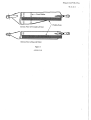
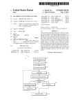
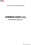
, LUFTFARTSDIRE KTORA TET Avd. for Luftfartsinspeksjon FORNEBU-OSLO/Dep. Tlf. : Oslo (02) MAULE SAMENDRAG LUFTDYKTIGHETSPÂBUD 121340 AFTN: ENFBYA Tlgr. : CIVILAIR OSLO Telex: 11032 Oslo 1946 - 1970 (LDP) Med hjemmel i lov om luftfart av 16. desember 1960 § 47,2. ledd og § 214, Kgl. res av 8. desember 1961, litra K og Samferdselsdepartementets bev datert 23. mars 1964, fastsetter Luftfartsdirektoratet f\flgende forskrift. 8/68 BESKYTTELSE AV BENSINLEDNING UNER FORRESTE SETE I MAULE Forandringen er IIMandatory" og gj elder for fØlgende modeller av Maule: M4 ~ M4e, M4T ~ M4s ~ M-4-210 ~ M-4-210e, M-4-220e og M-4-220S. Med serie nr.: 68-94, ie-ioe~ lT-3T, LS-3S, 1001-1045~ iooie- 1062e, 2001e-2004e og 2001S. Bensinledningen i cockpit på nevnte fly ligger så nær justeringshåndtaket for se~et at det er mulighet for å gripe feil når man skal flytte setet og derved lage bensinlekkasje innvendig i flyet. (. Luftfartsdirektoratet bestemer derfor at fabrikkens påbudt e for- andring i Service Letter nr. 13 av 29. august 1967 skal gjØrÆs gj eldende for alle norskregistrerte fly av nevnte typer. Forandringen går ut på at det skal monteres beskyttelsesplater på senterseksjonen foran bensinrØret slik at det ikke lenger er mulig å gripe feil. Platenes fasong og befestigelse fremgår av skisser i nevnte S.L. fra Maule~ som kan fås fra fabrikken eller fra forhandleren i Norge. 19/68 FORADRING AV SIDETRIMRORETS OPPLAGRINGER P MAULE Forandringen gj elder for fly av Maule M-4 " " " " " " " M-4e M4s M4T M-4-210 M-4-210e M-4-220S M-4-220e SIN " " " " " " " t'ypene: til" og med 94 is " " IT 1001 1001 2001S 2001e " 3 ie " " " " " " " " " " " " " " " " " ioe 3S 3T 1045 1064e 2003S 2006e Luftfartsdirektoratet bestemmer herved at trimrorets opplagringer i sideroret på de ovenfor nevnte fly skal forandres i henhold til Maule Aircraft Carp. Service Letter No. 14 så snart som mulig~ og senest ved fØrste 25 timers ettersyn. Service Letter No. 14 datert 19. februar 1966 fås ved henvendelse til forhandleren av flytypen. Ref.: FAA AD No. 68-7-8 og LVA 305/68. ( F o r a' a n g i e I d e ~ d e f I Y'" J t e ,. . lJ t f c- r ~ :- e n i ':' r ~ - .. . f! .: ;. .: .. skei '.'CE~e ~~~'::vk:i;;1 ~.:. ::.Òtudi": ','.02 e LJ i f : ,. -', r: i ti: ';d ~ nota: ,)i. LUFTDYKTIGHETSP ÂBUD 17/69 Maule 2 FORANDRING AV TRINSE FOR BALASERORS WIRE P KONTROLLS0YLEN I MAULE Forandringen gj elder fØlgende fly av typen Maule: M-4 M-4T M-4e M-4s M-4-210 M-4-210C M-4-220C SIN SIN SIN SIN S N SIN SIN 3 til og med 94 IT tii og med 3T ie til og med iie is til og med 3S 1001 til og med 1045 100lC til og med 1075C ~ 107ge og 1080c 2001C til og med 202ge og 2032C på grunn av a~ lageret i den forreste trinse for balanserors wire som er montert nederst på kontroiisØylen på de ovenfor nevnte fly kan iØsne og trinsen derved falle av ~ bestemmer Luftfartsdirektoratet at fØlgende forandring skal utfØres: For å hindre trinsen i å falle av opplagringsbolten i tilfelle som nevnt, skal det monteres en stor skive på forsiden av trinsen og opplagringsbolten skal skiftes ut med lengre bolt. Den nye bolten settes inn forfra med skivene i fØlgende orden: 1. .Aj~5-27 bol t med hode 2. AN97 0- 5 ski ve 3. AN960-516 ski ve 4. 5. Trinse KentroiisØylen 6. Ai'1j960-516 skive 7. AN365-524 mutter forover Forandringen skal utfØres ved fØrste 25 timers ettersyn. Ref.: FAA AD No. 69-20-2 og Maule Service Letter No. 19, datert 4. september 1969 omhandler same sak. ( ',g~J,;, ..'-'-.LUFTF ARTSVERKET Hovediicmi ni slr(JS;'Jf'(:n Avd. for iufirortslns~"=r'SJOfl Postboks 18. 1330 Oslo lulihovn Telelo,' Oslo (02, '21j40 AFTN ENFBYE WJ lUFTDYKTIGHETSpABUD Motordrevne luft- (lDP) Erstatter Maule-l Tigr . eIVILpIF. OSLO Telex 17011 Idõl n farØy Maule- la Med hjemmel i lov om luftfart av 16. desember 1960 ŠŠ 214 og 43 jfr. kgL. res av 8. desember 1961, ¡itra K og Samferdselsdepartementets bemyndigelse av 23. mars 1964 fastsetter'luftfartsverk-et følgende forskrift om luftdyktighet. 48/75 KONTROLL OG MODIFIKAJON AV BENSINSYSTET P MAUL Påbudet gj elder: Maule Aircraft eorporation modell M-4-210 ~ M-4-210e og M-5-210e med fØlgende serienr. : M-4-2l0 ( M-4-210C M-5-210C serienr. 1001 serienr. lOOlC serienr. 6001e til og med 1045 til og med ii17e til og med 606ge ~ 6072e, 6076c, 6077e, 607ge, 608oe, 6084e, 6087e. Påbudet omfatter: For å hindre bensinlekkasje i fremre del av kabinen skal fØlgende kontroll og modifikasjon ~tfØres: 1. Vri bensinsystemets velgekran i posisjon "off" . 2. Demonter den del av bensinsystemets returledning fra motorens Il fuel injector", som går fra branskottet til sametanen. Returledningen er installert på venstre side i fremre del av kabinen. 3. Kontroll av den korte returledningen : Kontroller den korte delen av returledningen som er plassert mellom branskottet og enveisventilen for sprekker i området rudt flensene . Dersom en finner sprekker skal ledningen skiftes ut med ny etter generelle anvisninger gitt i FAA Advisory Circular 43.13. 4. Utskifting av den lange returledningen : Den del av returlednigen. som er plassert mellom enveisventilen og samertanen skal skiftes ut med ny ~ som gir en mer fleksibel innmontering. Den nye returledningen skal være 8" lang i 1/4" aluminiumsrØr av godkjent kvalitet og skal være utstyrt med godkjente "fittings". (Se FAA Advisory eircular 43.13 for retningslinjer.) på midten av returledningen skal det bØyes til en "lØke" med en diameter på 1,5" - 2,0". Ved montering av returledninger skal "lØken" plasseres horisontalt. 5. Monter enveisventilen med pilen pekende bakover. 6. UtfØr funsjonsprøve av den samenmonterte returledningen med hensyn til bensinlekkas j e. An.: Maule Aircraft Corporation Service Letter 31 omhandler same sak. ( fort s . 2. august 1979 _~ r -: ¡ '. : :: -: . . I Motordrevne luftfarØY Maule- L a Erstatter M~ule-l 48/75 forts. Tid for utfØrelse: Inen 30 flytimer regnet fra 20. juii 1975. Referanser: FAA AD 75-11-02 og Maule Aircraft eorporation Servce Letter 31 omhandler same sak. 1,44/79 KONTROLL AV FR R0RFESTE MEOM HAEFLATE OG SKROG Påbudet gj elder: Maule Aircraft eorp modeller M-4 og M-5 med serienr: til 94 til 1045 iS tii 3S lT til 3T ie til Ile M-5-210e s eri enr 6001C til M-5-220C 5001C til M-5-210TC: M-4 Il serienr Il Il Il Il Il Il 4 M-4-210C 1001 M-4-220e M-4-18oe Il Il Il ser:enr M-4-22 os M-5 alle 6206e 5057e " 1001C 200lS 2001e 3001e Il II !l M-5-235C serienr M-5-180e Il 9001e til til til ¡OOlC 8001C 11117 e 2190e 3006e tii til 7283C 8004e Påbudet omfatter: For å ungå brudd på røret som fester fremre del av haleflatene til bakkroppen skal paragraf (l) og (51 i Maule Aircraft eorp Servic'e Bulletin No L datert 3. mai 1979 eller senere revisjo~er utfØres. Dersom sprekker blir funnet skal delene skiftes ut med nye deler fra Maule Aircraft Corp fØr fØrste flyging. Forandre haleflate ii skrog festet som vist i ovennevnte Service Bulletins paragraf (3) og 4). Tid for utfØrelse: Innen 25 timers gangtid etter 2. august 1979 denne dat~ det som kommer fØrst. eller 60 dager etter Referanser: FAA AD 79-12-01 ~ Q. U Ui.v' \ '+~ 2~ust 1979 LUFTFARTSVERKET H oveda d m ¡nistra s jo n en Avd, for luftfartsinspeksjon Posibokc 18. 1330 Oslo lufthavn Talefon: Oslo (02) 59 '3:l 40 AFTN : ENFBYE Motordrevne luft- LUFrDYKTIGHETSPÅBUD Tlgr, : CIVILAIR OSLO Telex : 17011 Ida fartØy Maule-2 (LDP) in Med hjemmel i lov om luftfart av 16. desember 1960 §§ 214 og 43 jfr. kgL. res. av 8. desember 1961, Htra K og Samferdselsdepartementets bemyndigelse av 23. mars 1964 fastsetter Luftfartsverket følgende forskrift om luftdyktighet. 47/81 REARSJON- OG UTSKIFTING AV SIDERORSPEDALEN "V-BA"-RØR Påbudet gjelder: Maule Aircraft eorp. modeller M-4 med serienr. 1001 til og med 1045 og M-4-210C med serienr. 1001 C til og med 1117 C. Påbudet omfatter: For å forhindre svikt i siderorspedalens "V-bar" og tilhØrende strutur skal llV-barll-rØret kontrolleres for sprekker ved hjelp aven lupe som forstØrrer minst 10 ganger. Anmerk.:. Maule Aircraft Corp Service Bulletin nr. 2, datert 17. februar 1981 eller senere revisjoner viser fremgangsmåte for demontering for å gjøre rorpedalrØret tilgjengelig. Dersom i~gen sprekker biir funnet skal rØret modifiseres som vist i S.B.. l. Dersom sprekker biir funnet skal pkt. 2 eller 3 utfØres fØr fØrste flyging. 2. Dersom sprekker på l tomme eller lmindre biir funnet skal liV-barn-rØret skiftes ut med modifisert rØr med delnr. 4130F-12 som angitt i S.B. eller sprekken stoppbores , sveises og forsterkes som vist iS. B. og i.h. t. Advisony Circular 43 .13A~ Chapter 2, Aircraft Metal Structure, Section 2, Nelding. 3. Dersom sprekker lengre L tomme blir funnet skal IIV-bar"rØret skiftes ut som i pkt. l.. Tid for utfØrelse: Innen 25 tiners gangtid etter 28-9-81. Referanser: FAA AD 81-14-02 Amendment 39-4146 28-9-81 ( MERK! For at angieIdende f1ymateriell skal være luftdyktig må påbudet være utfort til relltid og notat om utfore!sen forl i~¡,.i ved. LUFTFARTSVERKET \6/85 LDP DRENERING AV DRIVSTOFFSYSTEHET Påbudet q;elder: Maule Aerospace Technology r modell M-4 og M-5 r utstyrt med dreneringsplugger i hoved- og reservetankene . Påbudet omfatter: tankene skal dreneringspluggene skiftes ut med Quick Drain Valves i henhold til Maule Service Bulletin nr. 5 og Maule Service Letter nr. 32 eller senere 1. For å lette drenering av drivstoff revisjoner av disse. 2. FØlgende revisjoner skal inngå i flygehåndbØkene : M-4 .' AFM Rev. M-4-180C M-4-220C H-5-210C M-5-220C A A . . 2 A 5 B A M-5-180C M-5-210TC M-5-235C M-5-235C Rev. n A D B A (AFM datert 12.8.81) APM (datert 6.4.76) Supplement No 13 M-4-210 og M-4-210C AFM Supplement No. 10. Tid for utfØrelse: Innen 50 timers gang tid etter 8.2.85. Referanser: FAA AD 84-09-07. \. B . 2. B 5 LUFARTSVERT.,., ..'MOTORDREVNE H()veddnstrsjôntn '; , "FTFÁRTffY '.. . ..'J.Î1arInpeksjonep..'.' PostbkS..S 1:24,Dep. ,QQ3:20sli: .. Telefon ..: 2294 iÖjlÖ", . .. Telefax .. .:2294 2391." ..... o LUFTDYKTIGHETSPABUD ',TJgr. ': CIVILAI . (LDP) Telex:71032enf n , . .,. Med hjemmel 96-018 om lov om luftart av 11. jui 1993 kap. IV § 4-1 MAULE -3 og kap. XV § 15-4, fastsetter Lufdartvetket følgende forskrift om luftyktghet. KONTROLL OG UTSKITING AV ((WING LIFT STRUTS)) Påbudet gjelder: Maule Aerospace Technology, inc., følgende modeller: M-4, M-5, M-6, M-7, MX-7, MXT-7 alle serier, og MT-7-235, M-8-235 (alle serienummer) . , Påbudet omfatter: Utfør tiltak som beskrevet i V~!t~~,~' . Tid for utførelse: ~; /;';. .~¡t f5'~ '. , Innen 24.02.96. (NB.~g~%~iere er informert). ~;',,~;~i. , Referanse: ~,,"'t,~\ "i,~i.~~¡i"~i; ,~ FAA AD ' ,~~tt'~ 01.03.96 ( MERK! For at angjeldende flymateriell skal være luftyktg må påbudet være utført til rett tid og notat om utførelsen ført in i vedkommende journal med henvisnig til denne LDPs nummer. Bilag til LDP 96-018 O AIRWORTHINESS DIRECTIVE REGULATORY SUPPORT DIVISION P.O. BOX 26460 OKLAHOMA CITY, OKLAHOMA 73125-0460 . U.5. Department of Transportation Federal Aviation Administration The following Airwarthiness Direclive issued by the Federal Avialian Administralion in accrdance with the provisions of Federal Aviation Regulalions, Part 39, applies to an aircft medel of which our records indicale yau may be the registered owner. Airwortiness Direcives affecl avialian safety and are regulatians which require immediale ettenlion. You are caulioned that no person may aperale an aircraft to which an Airwariness Direclive applies, except in accrdance wit the requirements of the Airwartiness Direcive (reference FAR Subpart 39.3). 95-26-18 MAULE AEROSPACE TECHNOLOGY, INC.: Amendment 39-9476; Doeket No. 95-CE-97-AD. Applieability: M-4, M-5, M-6, M-7, MX-7, MXT-7 Series and Models MT-7-235, and M-8-235 Airlanes (all serial numbers), eerteated in any eategoiy that are equipped with par number (P IN) 2Q79E rear wig lit strts and PIN 2080E front wig lift strts. NOTE l: This AD applies to eaeh ailane identified in the preeeding applieability revision, regardless of whether it has been modifed, altered, or repaired in the area subjeet to the requirements of this AD. For airplanes that have been modified, altered, or repaired so that the perfonnanee of the requiremerits of this AD is affeeted, the owner I operator must request approval for an alternative method of eomplianee in aeeordanee with paragraph (b) of this AD. The request should include an assessment of the effeet of the modifieation, alteration, or repair on the unsafe condition addressed by this AD; and, if the unsafe eondition has not been eliminated, the request should include speeifie proposed aetions to address it. Complianee: Required within the next 30 ealendar days after the effeetive date of thisAD, unless already aeeomplished. NOTE 2: The eomplianee times and inspeetion intervals indieated in this AD take preeedenee over the eomplianee times and inspeetion intervals ealled for in the Maule Servce Bulletin (SB) No. L l, Issued: Oetober 30, 1995. NOTE 3: The paragraph strueture of this AD is as follows: Level l: (a), (b), (c), etc. Level2: (l), (2), (3), etc. Level3: (i), (ii), (iii), etc, Level2 and Level 3 stretures are designations of the Level L paragraph they immediately follow. To prevent eorrosion of the wing lift strt, whieh, if not deteeted and eorrected, eould eause the wig to separate from the airplane, aeeomplish the fo!lowing: (a) Inspeet the two rear wing lift struts, (P IN 2079E) and the two front wig lit strts (P IN 2080E) for internal eorrosion in aeeordanee with the INSTRUCTIONS and INSPECION PROCEDUR seetions speeifed in Maule SB No. L l, Issued: Oetober 30, 1995. (l) If evidenee of eorrosion damage is found, prior to furter ilght, aeeomplish one of the followig: (i) Replaee the damaged strt with an airworty strt of the same part number that has be en treated internally with eorrosion preventative in aeeordanee with the INSPECION PROCEDUR seetion speeified in Maule SB No. L l, Issued Oetober 30, L 995, or (ii) Replaee the damaged strt with a sealed wing lift strt, PIN 2200E or PIN 2201E, as applieable, in aeeordanee with the instretions specified in PART Il of the INSTRUCTIONS seetion of Maule SB No. L l, Issued Oetober 30, 1995. (2) If no evidenee of eorrosion damage is found, prior to furter ilght, treat the strt internaly with eorrosion preventative in aeeordanee with the NOTE in the INSPECION PROCEDUR seetion in Maule SB No. 11, Issued Oetober 30,1995. (b) An alternative method of eomplianee or adjustment of the eomplianee tie that provides an prove d by the Manager, FAA, AtIanta Aicraft Certcation Offiee, Campus Building, 1701 Columbia Avenue, suite 2-160, College Park, Georgia 30337-2748. The request shal be forwarded through an appropriate FAA Maintenanee Inspector, who may add comments and then send it to the Manager, AtIanta Aircraft Certcation Offee. NOTE 4: Information concerning the existence of approved alternative methods of complianee with this equivalent level of safety may be ap AD, if any, may be obtained from the AtIanta Aircraft Certfication Office. (c) The inspeetion and possible replaeements required by this AD shall be done- in aceordanee with Maule Service Bulletin No. L l, Issued: October 30, 1995. This in corporation by reference was approved by the Direetor of the Federal Register in aecordanee with 5 U.S.C. 552(a) and L CFR part 51. Copies may be obtained from Maule Aerospaee Technology, Inc., 2099 GA Hwy., 133 South, Moultre, Georgia, 31768. Copies may be inspeeted at the FAA, Central Region, Offce of the Assistant Chief Counsel, Room 1558, 601 E. 12th Street, Kansas City, Missouri, or at the Offce of the Federal Register, 800 North Capitol Street, NW., 7th Floor, suite 700, Washington, DC. (d) This amendment (39-9476) becomes effeetive on Januaiy 26, 1996. ( FOR FURTHER INFORMATION CONTACT: Cindy Lorenzen, Aerospaee Engineer, FAA, AtIanta Aireraft Certfication Office, Campus Building, 1701 Columbia Avenue, suite 2-160, College Park, Georgia 30337-2748; telephone (404) 305-7357; facsimile (404) 305-7348, LUFTFARTSVERKET MOTORDREVNE LUFTFART0Y H ovedadminstrasj onen Luftfartsinspeksjonen Postboks 8124 Dep" 0032 Oslo Telefon : 22 94 20 () o LUFTDYKTIGHETSPABUD (LDP) Telefax: 22 9423 91 Tlgr. : CIVILAIR Telex : 71032 enf n MAULE - 4 -Med hjemmel i lov av IL. juni 1993 nr,lOl om luftfart, kap, XV § 15-4 jLkap: IV§A,i og-Samferdselsdepartementets bemyndigelse av 25, mars L 96-041 994,-faststter Luftarverketfølgende forskríftom luftdykiighet. - OMPLASSERING AV ((GASCOLATOR)) OG DRIVSTOFFPUMPE Påbudet gjelder: Maule Aerospace Technolagies, Inc: Model M-4-210 SIN 1001 t.o.m. 1045 Model M-4-21OC SIN 100lC t.o.m. 1080C, som harinstallert ((Dual Exaust System 5230F)). Påbudet omfatter: Utfør tiltak som beskrevet i vedlagte kopi av FAA AD 96-10-05. Tid for utførelse: Innen neste 50 timers ettersyn etter 21.06.96, hvis ikke allerede utført. Referanse: FAA AD 96-10-05. Gyldighetsdato: 01.06.96. ( MERK! For at angjeldende flymateriell skal være luftdyktig må påbudet være utført til rett tid og notat om utførelsen ført inn i vedkommende journal med henvisning til denne LDPs nummer. AIRWORTHINESS DIRECTIVE REGULATORY SUPPORT DIVISJON P,O, BOX 26460 OKLAHOMA CITY, OKLAHOMA 73125-0460 o Bilag til LDP 96-041 U,S, Department af Transportation Federal Aviation Administration 'The following Airworthiness Dire'dive issued by the Federal Aviation--Administration;n accrçjance-wit-h the -provisjon! of'federal Aviatia-n Regulations, Part 39,.applies to an aircraf FAR Subpart 39.3). - made! of which aur records inQicale you may be the registered owner, Airworthiness.Diredives'atfed aviat1n 'safety and.sre.regulatiol' whidi (~uirå.irnr:edi~te attention. You are cautioned that no person may operate an aircraft lo whici an Airworthinass Direcive"applies, except in accrdance wrt ths"f'equirements of the Airworthiness "DirecivB -(reference 96-10-05 MAULE AEROSPACE TECHNOLOGlES, INC.: Amendment 39-9610; Docket No, 95-CE-22-AD. Applicability: The following airplane models and serial numbers, certicated in any category, that have Dual Exhaust System 5230F installed: Madel M-4-210 S-erial Numbers L 00 L through 1045 M-4-210C 1001C through 1080C NOTE l: This AD applies to each airplane identied in the preceding applicability provision, regardless of whether it has been modified, altered, or repaired in the area subject to the requirements of this AD. For airplanes that have been modifed, altered, or repaired so that the performance of the requirements of this AD is affected, the owner-joperator must request approval for an altemative method of compliance in accordance with paragraph (c) of this AD. The request should include an assessment of the effect of the modifcation, alteration, or repai on the unsafe condition addressed by this AD; and, if the unsafe condition has not been elimiated, the request should include specifc proposed actions to addressit. . 'Compliance: Requirea Within the next 50 hours tie-in-servce åIer the effective date of this AD, unl~ss already accomplislled. To prevent an airlane engie fire eau sed by the close proxity of the fuel gascolator and electrc fuel pump to the exhaust system, accomplish the following: ~ (a) Relocate the gascolator and fuel pump' from above the ai -egress to the left-side of the ailane in accordance with Maule Servce Bulletin No, LO, dated September 16, Ï994. (bl Special !light pennits may be issued in accordance with sections 21.197 and 21,199 of the Federa Aviation Regulations (14 CFR 21.197 and 21.199) to operate the airplane to a location where the requirments of this AD can be accomplished. (c) An altemative method of complice or adjustment of the compliance tie that provides an equivalent level of safety may be approved by the Manager, Atlanta Afcraft Certcation Office (ACO), Campus Building, 1701 Columbia Avenue, suite 2-160, _College Park, Georgia 30337-2748. The request shal be forwarded though an appropriate FAA Maitenance Inspector, who-may add coinents and then send it to the Manager, Atlanta ACO. NOTE 2: Information conceming the existence of approed altematIe methods of compliance with this AD, if any, may be obtained from the Atlanta ACO. (dl The relocation required by ths AD shal be done in accordance with Maule Servce Bulleti No. LO, dated September 16, 1994. This incorporation by reference was approved by the Director of the Federal Register in accordance with 5 U.S,C. 552(a) and L CFR par Sl. Copies may be obtaed from Maule Aerospace Technology, Inc., Lae Maule, Route 5, Box 318, Moultre, georgia 31768. Copies may be inspected at the FAA, CentrålRêgion, Office of1:e ÁSsistat Chief Counel, Room 1558,601 E. 12th Street, Kasas City, Missouri, OI"' at the Offce.of the Fedèrà Regitèr,800 NortCapitol StreetN'., suite'700, 'iáshihgtcin. DÇ~ . . (e) This amendment becomes effective on June 21, 1996. . FOR FURTHER INFORMTION CONTACT: Ms, Juanita Craft-LIoyd, Aerospace Engieer, EAA"Atlanta AIcraft OertcationOffce, Campus. Building, 170 L Columbia Avenue, suite 2-160, College Park, Georgia 30337-2748; telephone (404)"05-7373; facsime (404) 305-7348. \ LUFTFARTSVERKT MOTORDREVNE LUFTFART0Y Hovedadmstra~onen Lufdan~pek~onen Postboks 8124 Dep" 0032 Oslo Telefon : 22 94 20 00 o . LUFTDYKTIGHETSPABUD (LDP) Telefax: 22 94 23 91 Tlgr, : CIVILAIR Telex : 71032 enf n MAULE - 5 Med hjemmel i lov av 11. juni 1993 nr. 101 om luftart, kap. XV § 15-4 jf, kap. IV § 4-1 og Samferdselsdepartementets bemyndigelse av 25. mars 1994, fastsetter Lufdartverket følgende forskrift 98-018 om luftdyktighet. REVISJON A V FLIGHT MAAL Påbudet gjelder: Alle Maule modeller som er listet i vedlagte kopi av FAA AD 97-26-14. Påbudet omfatter: Utfør tiltak som beskrevet i vedlagte kopi av FAA AD 97-26-14. Tid for utførelse: Innewn 30 dager etter 1998-02-01, dersom ikke allerede utført. Referanse: FAA AD 97-26-14. Gyldighetsdato: 1998-02-01 (. . ( MERK! For at angjeldende flymateriell skal være luftdyktig må påbudet være udørt til rett tid og notat om udørelsen ført inn i vedkommende journal med henvisnig til denne LDPs nummer. Bilag til LDP 98-018 AIRWORTHINESS DIRECTIVE REGULATORY SUPPORT DIVISION P.O. SOX 26460 OKLAHOMA CITY, OKLAHOMA 73125-0460 o U.5.Department of Transportation Federal Aviation Administration The folloing Airwrtiness Dirøcive issuød by the Fødera( Aviøtio Administtion in acrdance wit the prisjons of Fedral Avialion Regulatio, Part 39, applies to an air model of whic our recrds indicale you may ba the registerød ower. Airworinass Diras afføc avialion safety an are regulations whic reqira immødiate atteniion. Vou ll cautionød thl no pe may opete an air lo whic an Airwiness Dirive applies, excepl in acanc wit tha requirements of th Airwiness Direce (refer FAR Subprt 39.3). 97-26-14 MAULE: Amendment 39-10257; Doeket No. 97-CE-40-AD. Applicabilty: The followig ailane madeIs, eertcated in anyeategory: - Models MX-7-420 and MX-7-420 ailanes, al serial numbers; and - Models M-7-235 and M-7-235A ailanes, al serial numbers, that are modifed in aceordanee with Maule Supplementa Tye Certcate (STC) SA2661S0. NOTE 1: Maule STC SA2661S0 includes the procedures for incorporatig the followig items on the Maule Models M-7-235 and M-7-235A ailanes: - an Alson 250-B1 7C gas turbine engie; - Edo Model 797-2500 amphibious floats; and - Harll Mode! HC-B3TF-7AjTl0173-11R or HC-B3TF-7AjTl01 73F-1 1R propellers. NOTE 2: This AD applies to eaeh ailane identied in the preceding applieabilty provision, regardless of whether it has been modifed, altered, or repaied in the area subjeet to the requirements of this AD. For airplanes that have been modifed, altered, or repaired so that the penormance of the reauirer..,..:!.ts of t.iis AD is affeeted, the owner j operator must request approval for an alternative met,-icd ..,f c::npliance in aceord2.~'.:e with paragraph (e) of this AD. The request should include an assessment of the effeet of the modifcation, alteration, or repai on the unsafe condition addressed by this AD; and, if the unsafe condition has not beeIl eliated, the request should include specifie proposed actions to address it. COTJplianr;~: Required within the next 30 days after the effective ¿"'te of this AD, unless aIeady aecompli",hed. To prevent loss of ailane control or engie overspeed with consequent loss of engie power caused by followig: . the po':.'cr levers being positioned below the flght idle stop while the ailane is in flght, accomplish the (a) knend the Limtations Section of the ailane flght manual (AFMj by insertg the followig 1mguage: ~Positioning of power levers below the flght idIe ;;top while in flght : S i-rohibited. ~ueh positioning could lead to loss of airlane contral or may result in an eugie overspeed eondition and eonsequent loss of engie power." (b) This action may be aceomplished by incorporating a copy of this AD into the Limtations Section of the AFM. (e) Amending the AFM, as required by this AD, ma:v be penormed by the ownerjoperator holding at least a private pilot certcate as authoried by section 43.7 of the Federal Aviation Regulations (14 CFR 43.7), and must be entered into the aicraft records showig compliance with this AD in aceordance with section 43.9 of the Federal Aviation Regulations (14 CFR 43.9). \ (d) Special flght permts rray be issued in aceoráance with seetions 21.197 i:d 21. 199 of t.'ce Federal AvIation Regulation", (14 CFR 21.197 and 21.199) to operate the airplane to a lccation where the rec:ilÌrements of this AD can be accomplished. (e) An alternative method of compliariee or adjustment of the compliance time that provides an equivalent leve! of safety may be approved by the Manager, Atlanta Aircraft Certcation Offee (ACO), Campus Building, 1701 Columbia Avenue, suite 2-160, College Park, Georgia 30337-2748. The request shal be forwarded through an appropriate FM Maitenanee Inspector, who may add eomments and then send it to the Manager, Atlanta ACO. NOTE 3: Information concerning the existenee of approved alternative methods of eompliance with this AD, if any, may be obtaed from the Atlanta ACO. (f) Information related to this AD may be examed at the FM, Central Region, Offce of. the Regional Counsel, Room 1558, 601 E. 12th Street, Kansas City, Missouri 64106. (g) This amendment (39-10257) beeomes effective on Januar 28, 1998. FOR FURTHER INFORMATION CONTACT: Wayne A. Shade, Aerospaee Engieer, FM, Atlanta Certfication Offee, 1895 Phoenix Boulevard, suite 450, Atlanta, Georgia 30349; telephone (770) 703-6094; facsime (770) 703-6097. i \ .":¡LQl~fb-R'fSV8R.8T¡:;..'. . "f-oyedädiliiisti-asjoneI1' ....Lútt(å¡-sillsp~ksj QneÒ'.m' ,. Post1iQki'¡.8I24pep.,'.Ob,3:ips!o. ,'tele .:2:294:iooq.,.::..... Tele. :z294239C'" TIgr., :CIVILAIR'.,. Telex:7I032 ëil D LUFTDYKTIGHETSPÀBUD (LDP) Med hjemmel i lov av IL. juni 1993 nr, 101 om luftfart, kap. XV § 15-4 jf. kap, iV § 4-1 og Samferdselsdepartementets bemyndigelse av 25, mars 1994, fastsetter Luftfartsverket følgende forskrift om luftdyktighet. 98-075A KONTROLL/UTSKIFTING AV "WING LIFT STRUT" Påbudet gjelder: Alle Maule modeller som er listet i vedlagte kopi av FAA Corrected AD 98-15-18. Påbudet omfatter: Utfør tiltak som beskrevet i vedlagte kopi av F AA Corrected AD 98- 1 5- 18. Tid for utførelse: Til de tider som beskrevet i vedlagte kopi av FAA Corrected AD 98-15-18, med virkning fra denne LDP's gyldighetsdato. Anm.: Denne LD? erstatter og opphever LDP 96-018. Referanse: FAA Corrected AD 98-15-18. Gyldighetsdato: 1998-12-01 ( MERK! For at angjeldende flymateriell skal være luftdyktig må påbudet være utført til relt tid og notat om utførelsen ført inn i vedkommende journal med henvisning til denne LDPs nummer. Bilag til LDP 98-075A o CORRECTED AIRWORTHINESS DIRECTIVE REGULATORY SUPPORT DIVISION P,O. BOX 26460 OKLAHOMA CITY, OKLAHOMA 73125-0460 u.s, Department of Transpartation Federal Aviation Administration The rollowing Airworthiness Directive issued by the Federal Aviation Administration in accrdance with the provis¡ons of Federal AviaUon Regulations, Part 39, applies lo an aircraft madel of which aur records indicate you may be the registered owner. Airworthiness Direc!ives affect avialion safety and are regulations which require immediate atlantion. You are cautioned lhal no person may operal. an aircraft to which an Airworthiness Directive applies, except in accrdance wilh the requirements of the Airworthiness Directive (reference FAR Subpart 39.3). 98-CE-OI-AD; 98-15-18 MAULE AEROSPACE TECHNOLOGY CORP.: Amendient 39-10669; Docket No. Supersedes AD 95-26-1S, Amendient 39-9476. Applicability: The following airlane mo dels, all serial numbers, certificated in any category, that are equipped with par number (P/N) 2079E (or F AA-approved equivalent par number) rear wing lift strts or P/N 2080E (or FAA-approved equivalent par number) front wing lift strts: M-4 M-4-ISOC M-4-21OC M-4-220C M-5-200 M-5-235C MX-7-235 MT-7-235 MX-7-180A M-7-235B Bee Dee M-4 M-4T M-4-210 M-4-220 M-5-l80C M-5-220C M-7-235. MXT-7-180 MXT-7-l60 MXT-7-420 NOTE l: M-4C M-4-l80S M-4-210S M-4-220S M-5-2 ioc M-6-l80 MX-7-l80 M-8-235 MXT-7-ISOA M-7-235A M-4S M-4-1S0T M-4-210T M-4-220T M-5-2 ioTC M-6-235 MX-7-420 MX-7-160 MX-7-l80B M-7-235C This AD does not apply to airlanes equipped with four Maule sealed lift strts, P/N 2200E and P/N 220 lE. These sealed lift strts are identified by two raised weld spots on the upper end of the strt just below the serial number plate. Removal of the upper cuffis needed to locate the weld spots. NOTE 2: This AD applies to each airla.'1e identified in the preceding applicability provision, regardless of d, or repaired in the area subject to the requirements of this AD. For aIIlanes that have been modified, altered, or repaired so that the performance of the requirements of this AD is aftected, the whether it has been modified, altere owner/operator must request approval for an alternative method of compliance in accordance with paragraph (e) of this AD. The request should include an assessment of the effect of the modification, alteration, or repair on the unsafe condition addressed by this AD; and, ifthe unsafe condition has not been eliminated, the request should incIude specific proposed actions to address it. Compliance: Required as indicated in the body ofthis AD, unless already accomplished, To prevent failure of the wing lift strts caused by corrosion dam age, which could eventually result in the wing separating from the ai.lane, accomplish the following: NOTE 3: The paragraph strcture ofthis AD is as follows: . Level l: (a), (b), (c), etc. Level2: (1), (2), (3), etc. Level 3: (i), (ii), (iii), etc. Level2 and Level 3 strctures are designations of the Level L paragraph they iimediately follow. (a) Upon accumulating 2 years on a lift strt affected by this AD; within 3 calendar months after the effective date of this AD; or within 2 years after the last inspection accomplished in accordance with AD 95-26-18 (superseded by this action), whichever occurs later, remove the wing Iift strts in accordance with the INSTRUCTIONS section of Maule Service Bulletin (SB) No. IL, dated October 30, 1995, and accomplish one of the following (the actions in either paragrph (a)(l), (a)(2), (a)(3), or (a)(4), incIuding all subparagraphs, ofthis AD): (1) Inspect the wing Iift strts for corrosion in accordance with the INSPECTION PROCEDUR section of Maule SB No. i l, dated October 30,1995. (i) If no perceptible dents (as dermed in the above SB) are found in the wing lift strt and no corrosion is externally visible, apply corrosion inibitor to each strt in accordance with Maule SB No. li, dated October 30, 1995. Re-inspect the wiIg Iift strts at intervals not to exceed 24 calendar months provided no perceptible dents or external corrosion is found. ( I Bilag til LDP 98-075A 2 98-15-18 ::tober 30, 1995. Re-inspect the wing lift strts at inte~als not to exceed 24 calendar months provided no perceptible ,ents or external corrosion is found. (ii) If a perceptible dent (as dermed in the above SB) is found in the wing lifr strt or external corrosion is found, prior to furter flight, accomplish one of the installations (and subsequent actions presented in each paragraph) specified in paragraphs (a)(3) and (a)(4) ofthis AD. (2) Inspect the wing Iift strts for corrosion in accordance with the Appendix to this AD. The inspection procedures in this Appendix must be accompIished by a Level 2 or Level 3 inspector certified us ing the guidelines established by the American Society for Non-destrctive Testing, or MIL-STD-4l0. (i) If no external corrosion is found and all requirements in the Appendix to this AD are met, prior to fuer flght, apply corrosion inibitor to each strt in accordance with Maule SB No. 11, dated October 30, 1995. Reinspect the lifr strts at intervals not to exceed 24 calendar months provided no external corrosion is the requirements incIuded in the Appendix ofthis AD are met. found and all of (ii) If external corrosion is found or if any of the requirements in the Appendix of this AD are not met, prior to furter flight, accomplish ane of the installations (and subsequent actions presented in each paragraph) specified in paragraphs (a)(3) and (a)(4) ofthis AD. (3) Install original equipment manufactuer (O EM) par number wing lift strts (or FAA-approved equivalent part numbers) that have been inspected in accordance with the specifications presented in either paragraph (a)(l) or (a)(2) of this AD, and are found to be airorty according to the inspection requirements incIuded in these paragraphs. Accomplish this installation in accordance with the applicable maintenance manuaL. Thereafter, inspect ~se wing lifr strts at intervals not to exceed 24 calendar months in accordance with the specifications presented in ither paragraph (a)(l) or (a)(2) ofthis AD. (4) . . Install new Maule sealed wing lifr strts, P/N 2200E or P/N 220lE, as applicable (or FAA-approved equivalent par nurnbers) on each wing as specified in the INSTRUCTIONS section in Par Il of Maule SB No. 11, dated October 30, 1995. (b) Ifholes are driIed into the sealed wing lift strt assemblies installed as specified in paragraph (a)(4) ofthis AD in order to attch" ciiffs, door cIips, or other hardware, inspect the wing lifr strts at intervals not to exceed 24 calendar months using the procedures specified in either pargraph (a)(1) or (a)(2), incIuding all subparagraphs, of this AD. (c) The repetitive inspections required by this AD may be terminated after installing new wing lift strt assemblies as specified in paragraph (a)(4) ofthis AD provided no holes are driled in these strt assemblies as specified in paragrph (b) ofthis AD. (d) Special flght permits may be issued in accordance with sections 21.197 and 2 L .199 of the Federal A viation Regulations (14 CFR 21.97 and 21.99) to operate the airlane to a location where the requirements of this AD can be accomplished. (e) An alternative method of compIiance or adjustment of the initial or repetitive compliance times that provides an equivalent level of safety may be approved by the Manager, Atlanta Aircraft Certification Offce (ACO), One Crown Center, 1895 PhoenIx Boulevard, suite 450, Atlanta, Georgia 30349. (1) The request shall be forwarded though an appropriate F AA Maintenance Inspector, who may add (. mnents and then send it to the Manager, Atlanta ACO. (2) Alternative methods of compIiance approved in accordance with AD 95-26-18 are considered approved as alternatlve methods of compliance for this AD. NOTE 4: Information concerning the existence of approved alternative methods of compliance with this AD, if any, may be obtained from the Atlanta ACO. (f) The removal, the lift strt inspection (in paragraph (a)(1) ofthis AD), the applications, and the installation required by this AD shall be done in accordance with Maule Service Bulletin No. 11, dated October 30, 1995. This incorporation by reference was previously approved by the Director of the Federal Register as of January 26, 1996 (61 FR 623, Januar 9, 1996). Copies may be obtained from Maule Aerospace Technology, Inc., 2099 GA Hwy. 133 South, Moultre, Georgia 3 1768. Copies may be inspected at the F AA, Centrl Region, Offce of the Regional Counsel, Room 1558, 601 E. 12th Street, Kansas City, Missouri, or at the Offce of the Federal Register, 800 North Capitol Street, NW, suite 700, Washington, DC. (g) This amendment supersedes AD 95-26-18, Amendment 39-9476. (h) This amendment becomes effective on September 9, 1998. FOR FURTHER INORM nON CONTACT: Cindy Lorenzen, Aerospace Engineer, F AA, Atlanta Aircraft Certification Offce, One Crown Center, 1895 Phoenix Boulevard, suite 450, Atlanta, Georgia 30349; telephone: (770) 703-6078; facsimile: (770) 703-6097. Bilag til LDP 98-07SA 98-15-18 3 APPENDIX TO AD 98-15-18 PROCEDURES AND REQUlREMENTS FOR UL TRASONIC INSPECTION OF MAULE WING LlFT STRUTS EQUlPMENT REQUIRMENTS l. A portable ultrasonic thickness gauge or flaw detector with echo-to-echo digital thickness readout capable of 'eading to 0.00 L inch and an A-trace waveform display wiI be needed to accomplish this inspection. 2. An ultrasonic probe with the foIIowing specifications wiI be needed to accomplish this inspection: io MH (or iigher), 0.283 inch (or smaIIer) diameter dual element or delay line transducer designed for thickness gauging. The ransducer and ultrasonic system shaII be capable of accurately measuring the thickness of AISI 4340 steel down to ).020 inch. An accuracy of +/- 0.002 inch thoughout a 0.020 inch to 0.050 inch thickness range while calibrating shall Je the criteria for acceptance. p wedge made of 4340 stee1 (or similar ste ei with equivalent sound velocity) or at L. Either a precision machined ste east thee shim samples of same material wiI be needed to accomplish this inspection. One thickness of the step wedge Jr shim shall be less than or equal to 0.020 inch, one shall be greater than or equal to 0.050 inch and at least one other ;tep or shim shall be between these two values. L Glyceri, light oil, or similar non-water based ultrasonic couplants are recommended in the setup and inspection )rocedures. Water-based couplants, containing appropriate corrosion inibitors, may be utilized, provided they are 'emoved from both the reference standards and the test item after the inspection procedure is completed and adequate :orrosion prevention steps are then taken to protect these items. NOTE: Couplant is defmed as "a substace used between the face of the transducer and test surace to improve ransmission ofultrasonic energy across the transducer/strt interface." NOTE: If surface roughess due to paint loss or corrosion is present, the surface should be sanded or polished :mooth before testing to assure a consistent and smooth surace for making contact with the transducer. Care shall be aken to rem ove a minimal amount of strctual materiaL. Paint repairs may be necessar after the inspection to prevent 'urter corrosion damage from occurg. Removal of surace iregularities wiI enhance the accuracy of the inspection echnique. NSTRUMENT SETUP Set up the ultrasonic equipment for thickness measurements as specified in the instrments user's manuaL. 3ecause of the varety of equipment available to perform ultrasonic thickness measurements, some modification to this ;eneral setup procedure may be necessar. However, the tolerance requirement of step 13 and the record keeping equirement of step 14, must be satisfied. ~. If battery power wiI be employed, check to see that the battery has been properly charged. The testig wil tae ipproximately two hours. Screen brightness and contrt should be set to match environmental conditions. I. Verify that the instrent is set for the tye of transducer being used, i.e. single or dual element, and that the requency setting is compatible with the transducer. ~. lf a removable delay line is used, rem ove it and place a drop of couplant between the transducer face and the delay ine to assure good transmission ofultronic energy. Reassemble the delay line transducer and continue. ). Program a velocity of 0.231 inch/microsecond into the ultronic unit unless an alternative instrment calibration irocedure is us ed to set the sound velocity. the EQUIPMENT REQUIRMENTS. Place the probe on the hickest sample using couplant. Rotate the transducer slightly back and forth to "ring" the transducer to the sample. l. Obtain a step wedge or steel shims per item 3 of \.djust the delay and range settings to arive at an A-trace signal display with the first backwall echo from the steel near he left side of the screen and the second backwaII echo near the right of the screen. Note that when a single element ransducer is used, the initial pulse and the delay line/steel interface wiI be off of the screen to the left. Adjust the gain to ilace the amplitude of the first backwall signal at approximately 80% screen height on the A.:trace. r. "Rig" the transducer on the thinest step or shim using couplant. Select positive half-wave rectified, negative ialf-wave rectified, or fitered signal display to obtain the cleanest signaL. Adjust the pulse voltage, pulse width, and lamping to obtain the best signal resolution. These settings can vary from ane transducer to another and are als lepen o user dent. ds at the second iackwaII echo. (Measuring between the first and second backwaII echoes wiI produce a measurement of the steel hickness that is not affected by the paint layer on the strt). rf instability of the gate trigger occurs, adjust the gain, gate ;, Enable the thickness gate, and adjust the gate sa that it star at the first backwaII echo and en evel, and/or damping to stabilize the thickness reading. Bilag til LDP 98-075A 4 98-15-18 9. Check the digital display reading and if ¡tdoes not agree with.the known thickness of the thinnest thickness, follow your instrments calibration recommendations to produee the correct thickness reading. When a single element 'lnsdueer is us ed this wiI usually involve adjusting the fine delay setting. 10. Place the transducer on the thickest step of shim using couplant. Adjust the thickness gate width so that the gate is triggered by the second backwall reflection of the thick section. ff the digital display does not agree with the thickest thickness, follow your instrments calibration recommendations to produee the correct thickness reading. A slight adjustment in the velocity may be necessar to get both the thinnest and the thickest reading correct. Document the changed velocity value: L 1, Place couplant on an area of the lift strt which is thought to be free of corrosion and "ring" the transducer to surface, Minor adjustments to the signal and gate settings may be required to account for coupling improvements resulting from the paint layer. The thickness gate level should be set just high enough so as not to be triggered by irelevant signal noise. An area on the upper surface of the lift strt above the inspection area would be a good location to complete this step and should produee a thickness reading between 0.034-inch and 0.04l-inch. 12. Repeat steps 8, 9, L O, and L luntil both thick and thin shim measurements are within toleranee and the lift strt measurement is reasonable and steady. 13. Verify that the thickness value shown in the digital display is within +/- 0.002 inch of the correct value for each of the three or more steps of the setup wedge or shims. Make no fuer adjustments to the instrment settings. 14. Record the ultrasonic versus actual thickness of all wedge steps or steel shims available as a record of setup. INSPECTION PROCEDUR 1. Clean the lower 18 inches of the wing lift strts us . ease wil adversely affect the accuracy of ing a cleaner that wiI rem ove all dir and grease. Dir and o be required to the inspection technique. Light sanding or polishing may als reduce surace roughness as noted in the EQUlMENT REQUIR.MNTS section. 2. Us ing a flexible roler, draw a 1/4-inch grd on the surace of the strt as the first L L inches from the lower end of I shown in Maule Service Bulletin No. L l, dated October 30,1995, as applicable. This can be done us ing a soft (#2) pencil and should be done on both faces of the strt. As an alternative to drawing a complete grid, make two rows of marks spaced every 1/4 inch across the width of the strt. One row of marks should be about IL inches from the lower end of the strt, and the second row should be several inches away where the strt star to narow. Lay the flexible roler the two rows and use tape or a robber band to keep the riler in place. See Figure 1. . between respective tick marks of 3. Apply a generous amount of couplant inside each of the square areas or along the edge of the roler. Re-application of couplant may be necessar. 4. Place the transducer inside the first square area of the drawn grid or at the flIst 1/4-inch mark on the roler and "ring" the transducer to the strt. When using a dual element transdueer, be very careful to record the thickness value with the axis of the transducer elements perpendicular to any curvature in the strt. ff this is not done, loss of signal or inaccurate readings can result. 5. Take readings inside each square on the grd or at 1/4-inch increments along the roler and record the results. When taing a thickness reading, rotate the transducer slightly back and fort and experiment with the angle of contact to produee the lowest thickness reading possible. Pay close attention to the A-scan display to assure that the thickness gate is trggering off of maximized backwall echoes. . NOTE: A re ad ing shall not exceed .041 inch. ff areading exceeds .041 inch, repeat steps 13 and 14 of the 'STRUMENT SETUP section befare proceeding further. . ö. ff the A-trace is unsteady or the thickness reading is clearly wrong, adjust the signal gain and/or gate setting to obtain reasonable and steady readings. ff any instrent setting is adjusted, repeat steps 13 and 14 of the INSTRUMENT SETUP section be fore proceeding fuer. 7. In areas where obstrctions are present, tae a data point as close to the correct area as possible. NOTE: The strt wall contains a fabrication be ad at approximately 40% of the strt chord. The be ad may interfere with accurte measurements in that specific location. 8. A measurement of 0.024 inch or less shall require replacement of the strt prior to fuher flight. 9. ff at any time durg testing an area is encountered where a valid thickness measurement canot be obtained due to a loss of signal strengt or quality, the area shall be considered suspect. These areas may have a remaining wall thickness of less than 0.020 inch, which is below the range oCthis setup, or they may have small areas of localized corrosion or pitting present. The latter case wiI result in a reduction in signal strengt due to the sound being seattered from the rough surface and may result in a signal that includes echoes from the pits as well as the backwalL. The suspect October 30, 1995. I area(s) shall be tested with a Maule "Fabric Tester" as specified in Maule Service Bulletin No. 11, dated io. Record the ¡ift strt inspection in the aircraft log book. \ Bilag til LDP 98-075A 98-15-18 5 .- Pencil Ivarks Bottom View ofFoiw Li Strut Bottom View of Re ar Li Strut Figure i AD 98-15-18 ( LUFTFARTSTILSYNET 1. TILSYNSAVDELING Postboks 8050 Dep., 00310s10 Besøksadresse: Rådusgata 2, Oslo MOTORDREVNE LUFFART0Y LUFTDYKTIGHETSP ÄBUD Telefon : 23 31 78 00 Telefax: 23 31 79 96 E-post: postmottak(Wcaa.dep.no lLDP) MAUL - 7 Med hjemmel i lov av 11. juni 1993 nr, 101 om luftfart, kap. XV § 15-4 jf, kap. IV § 4-1 og Samferdselsdepartementets bemyndigelse av 25. mars 1994, fastsetter Luftfartstilsynet fØlgende forskrft om luftdyktighet. 2000-041 "NICOPRESS ™ SLEEVE TERMINAL ENDS" Påbudet gjelder: Maule Aerospace Technology, Inc., modeller og serienummer som beskrevet i vedlagte kopi av FAA AD 2000-09-06. Påbudet omfatter: Utfør tiltak som beskrevet i vedlagte kopi av FAA AD 2000-09-06. Tid for utførelse: Til de tider som beskrevet i vedlagte kopi av FAA AD 2000-09-06, med virkning fra denne LDP's gyldighetsdato. Referanse: F AA AD 2000-09-06. Gyldighetsdato: 2000-06-01. \ MERK! For at angjeldende flymateriell skal være luftdyktig må påbudet være utført til rett tid og notat om utførelsen ført inn i vedkommende journal med henvisning til denne LDPs numer, AIRWORTHINESS DIRECTIVE REGULATORY SUPPORT DIVISION P.O. SOX 26460 OKLAHOMA CITY, OKLAHOMA 73125-0460 el U.S. Department of Transportation Federal Aviation . AD's are posted on the internet at http://av-info.faa.gov Administration The following Airworthiness Directive issued by the Fedral Aviation Administration in accrdance wih the provisions of Tilla 14 of tha Coda of Fedral Regulations (14 CFR) part 39, applies to an aircraft mod! of which our records indicate you may ba the registered owner. Airworthiness Diractives affec avition safat lind are regulations which require immediate altention. Vou are caUlioned that no parson may operata an aircraft to which an Airwrthiness Directive applies, excpl in accordance wih the raquiremenls of the Alrwrthiness Directive (reference 14 CFR part 39, subpart 39,3). 2000-09-06 MAULE AEROSPACE TECHNOLOGY, INC.: Amendment 39-11715; DocketNo. 2000-CE-04-AD. (a) Wbat airplanes are affected by tbis AD? This AD affects the following airplane models and serial numbers, certificated in any category: GROUP 1 AIRLANS Models MX-7-160C M-7-260C M-7-420AC MX-7-ISOC MT-7-260 M-7-260 M-7-235C M-7-235A M-7-235B MX-7-1S0B MXT-7-1S0A MX-7-1S0A MX-7-160 MXT-7-160 MT-7-235 M-S-235 MXT-7-1SO MX-7-1S0 MX-7-235 M-7-235 M-6-235 Serial Num bers 3400 L C. 3000LC through 30004C, 30007C through 30011C, 30013C, and 30014C. 2900 L C. 2S00lC through 2S01 IC. 2700LC and 27003C. 26002C throuAA 26007C. 2500LC througb 25037C, 25040C, 25041C, and 25044C. 24001C. 2300LC through 23056C, 2305SC, and 23059C. 2200 L C though 220 L 6C. 21001C through 21067C, 21070C, 21072C, 21076C, 21077C, 21079C, and 210S1C. 20001C through 20063C. 19001C through 19046C. L 700 L C thouAA L 700SC. L SOO L C throuAA L S04 L C, L S044C, and L S047C. 15001C throuiih 15005C. 14000C throuJ; 14095C. l L 066C throuiih L L 097C. 100SIC throuJ; io122C. 407SC, 4080C, 40S3C, 40S6C, and 40S9C through 4132C. 750SC, 7S10C, 7S16C, and 7S1SC through 7S21C. ~ 2 2000-09-06 ( ROUP 2 AILAS Models Serial Numbers Bee Dee M-4 M-4 M-4C M-4S M-4T 3 through 14. M-4-21 O 3 through 94 (Bee bêê: 3~.14; and M-4: 1 C through 1 1 C. .. 15-94). f , is, 2S, and 3S. 1 T, 2T, and 3T. 1001 through 1045. M-4-210C M-4-220C M-4-220S io01C throuJlh 11 17C. 2001 C throuJlh 21 90C. 2001S. M-4- 1 80C 3001C throuJlh 3006C. M-5-200 M-5-210C M-5-220C M-5-235C , 8015e and 8022C. 6001 C throuJlh 6206C. 5001C throuJlh 5057C. 7001C through 7248C, 7250C through 7353C, A7354C, A7355C, 7356C, 7357C, A7358C, 7359C, A7360C, A7361C, 7362C through 7365C, A7366C, A7367C, 7368C through 7376C, 7445C, 7451C, 7460C, 7467C, 7470C, 7478C through 7480C, 7484C throuJlh 7487C, and 7515C. M-5- 1 80C 8001C through 8014C, 8016C through 8019C, 8021C, 8023C through 8042C, 8044C through 8064C, and 8068C through 8094C. M-5-210T M-6-235 9001 C throuJlh 901 OC. 7249C, 7356C, 7379C though 7444C, 7446C through 7450C, 7452C through 7459C, 7461C through 7466C, 7468C, 7469C, 7471C through 7475C, 7488C through 7507C, 7509C, 7511C through 7514C, and 751 7C. M-6- 180 8020C, 8043C, and 8065C through 8067C. M-7-235 4001 C through 4077C, 4079C, 4081 C, 4082C, 4084C, 4085C, 4087C, and 4088C. M-7-235 12001C and 12002C. These airplanes were manufactured as Model M-7-235 airplanes and then modified in accordance with STC SA2661S0. This modification changed the model designation ofthese airplanes to M-7-420. MX-7-235 MX-7-180 MX-7-420 10001 C through 10080C. .1 1001 C thmugh 1 L 065C. 13001C through 13003C. (b) Wbo must comply witb this AD? Anyone who wishes to operate any of the above airplanes on tae HS. Register must comply with this AD. (c) Wbat problem does tbis AD address? The actions specifiedby this AD are intended to detect and correct improper crimping of the Nicopress™ sleeve, which could cause a control cable to slip from the sleeve. This could result in loss ofrudder, elevator, aileron, or flap control. ( 3 2000-09-06 (d) What must I do to address this problem? To address this problem, accomplish the following: Action Compliance Time Procedures Inspect all Nicopress™ For Group 1 airplanes: Accomplish in accordance sleeve terminal ends for Within the next 25 hours correct size compression. time-i with the ACTION TO BE n-service (TIS) after T AKEN AN TOOLS May 30, 2000 (the effective REQUlD section of date ofthis AD); and Maule Mandatory Service For Group 2 airplanes: Bulletin No. 20, dated December 27, 1999. Within the next 100 hours TIS after May 30, 2000 (the effective date ofthis AD). Adjust or replace any Prior to further flght after terminal compressions that the inspection are outside of the limits this AD. required by Accomplish in accordance with the ACTION TO BE specified ID the service T AKEN AND TOOLS REQUIRED section of information. Maule Mandatory Service Bulletin No. 20, dated December 27, 1999. Do not install a Nicopress™ As of May 30, 2000 (the Accomplish in accordance sleeve without assuring that effective date ofthis AD). with the ACTION TO BE the terminal compressions TAKEN AND TOOLS are within the limits REQUIRED section of specified ID the service Maule Mandatory Service information. Bulletin No. 20, . dated December 27, 1999. (e) Can I comply with this AD in any other way? (I) Y ou may use an alternative method of compliance or adjust the compliance time if: (i) y our alternative method of compliance provides an equivalent level of safety; and (ii) The Manager, Atlanta Aircraft Certification Offce (ACO), approves your alternative. Submit your request through an F AA Principal Maintenance Inspector, who may add comments and then send it to the Manager, Atlanta ACO. (2) This AD applies to each airplane identified in the precedingi:pplicabilty provision, regardless of whether it has been modified, altered, or repaired in the area subject to the reqiiirements of this AD. For airplanes that have been modified, altered, or repaired so that the performance of the requirements of this AD . is affected, the owner/operator must request approval for an alternative method of compliance in accordance with paragraph (e)(I) ofthis AD. The request should include an assessment of the effect of the modification, alteration, or repair on the unsafe condition addressed by this AD; and, if you have not eliminated the unsafe condition, specific actions you propose to address it. (f) Where can I get information about any already-approved alternative methods of compliance? Contact Cindy Lorenzen, Aerospace Engineer, F AA, Atlanta Aircraft Certitication Office, One Cl'wn Center, 1895 Phoenix Boulevard, suite 450, AtIanta, Georgia 30349; telephone: (770) 703-6078; facsimile: (770) 703-6097. 4 2000-09-06 (g) What if I need to fly the airplane to another location to comply with this AD? F AA can issue a special flight perm it under sections 21.197 and 21.199 of the Federal Aviation Regulations (14 CFR 21.197 and 21.99) to operate your airplane to a location where you can accomplish the requirements ofthis AD. (h) Are any service bulletins incorporated into this AD by reference? Y ou must accomplish the actions required by this AD in accordance with Maule Mandatory Service Bulletin No. 20, dated December 27, 1999. The Director of the Federal Register approved this incorporation by reference under 5 U.S.C. 552(a) and 1 CFR part Sl. You can get copies from Maule Aerospace Technology, Inc., 2099 Georgia Hwy. 133 South, Moultrie, Georgia 31768. Y ou can look at copies at F AA, Central Region, Offce of the Regional Counsel, 901 Locust, Room 506, Kansas City, Missouri, or at the Offce of Register, 800 North Capitol Street, NW, suite 700, Washington, DC. the Federal (i) When does this amendment become effective? This amendment becomes effective on May 30, 2000. FOR FURTIIER INFORM nON CONT ACT: Cindy Lorenzen, Aerospace Engineer, F AA, Atlanta Aircraft Certification Offce, One Crown Center, 1895 Phoenix Boulevard, suite 450, Atlanta, Georgia 30349; elephone: (770) 703-6078; facsimile: (770) 703-6097. Issued in Kansas City, Missouri, on April 27, 2000. Michael Gallagher, Manager, Small Airplane Directorate, Aircraft Certification Service. (, BLANK \


![[4910-13-U] DEPARTMENT OF TRANSPORTATION Federal](http://vs1.manualzilla.com/store/data/005730800_1-83b69f38eee92750e4a30066087ffbc6-150x150.png)