1
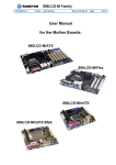
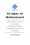
SBC81872 Socket 479 Full-size All-in-One CPU Card Series User’s Manual Disclaimers The information in this manual has been carefully checked and is believed to be accurate. AXIOMTEK Co., Ltd. assumes no responsibility for any infringements of patents or other rights of third parties which may result from its use. AXIOMTEK assumes no responsibility for any inaccuracies that may be contained in this document. AXIOMTEK makes no commitment to update or to keep current the information contained in this manual. AXIOMTEK reserves the right to make improvements to this document and/or product at any time and without notice. No part of this document may be reproduced, stored in a retrieval system, or transmitted, in any form or by any means, electronic, mechanical, photocopying, recording, or otherwise, without the prior written permission of AXIOMTEK Co., Ltd. ©Copyright 2005 by AXIOMTEK Co., Ltd. All rights reserved. April 2005, Version A1 Printed in Taiwan ESD Precautions Integrated circuits on computer boards are sensitive to static electricity. To avoid damaging chips from electrostatic discharge, observe the following precautions: Do not remove boards or integrated circuits from their anti-static packaging until you are ready to install them. Before handling a board or integrated circuit, touch an unpainted portion of the system unit chassis for a few seconds. This helps to discharge any static electricity on your body. Wear a wrist-grounding strap, available from most electronic component stores, when handling boards and components. Trademarks Acknowledgments AXIOMTEK is a trademark of AXIOMTEK Co., Ltd. IBM is a registered trademark of International Business Machines Corporation. MS-DOS, and Windows 2000 are trademarks of Microsoft Corporation. Award is a trademark of Award Software, Inc. IBM, PC/AT, PS/2, VGA are trademarks of International Business Machines Corporation. Intel and Celeron, Pentium M are trademarks of Intel Corporation. Other brand names and trademarks are the properties and registered brands of their respective owners. Table of Contents Chapter 1 Introduction 3 1.1 General Description 3 1.2 Specifications 2 1.3 Utilities Supported 3 1.4 Board Dimensions 4 Chapter 2 Jumpers and Connectors 5 2.1 Board Layout 5 2.2 Jumper Settings 6 2.2.1 LCD Voltage Selection : JP1 7 2.2.2 Clear CMOS: JP8 7 2.2.3 FSB Clock Selection : JP9 7 2.3 Connectors 8 Chapter 3 Installation 8 3.1 System Memory 9 3.2 CPU Installation 9 3.3 Configuring Power Supply 16 3.3.1 ATX Power Supply 16 3.3.2 AT Power Supply 16 3.4 Ultra DMA/66/100 Drive Installation 16 3.5 Completing Installation 17 Chapter 4 Hardware Description 18 4.1 Microprocessors 19 4.2 BIOS 19 4.3 General Output Connector: CN10 19 4.4 Enhanced IDE Interface Connector 21 4.5 Display Interface 22 4.5.1 Flat Panel/CRT Interface Controller 22 4.5.2 Features 22 4.5.3 VGA/LVDS Panel Connectors 24 4.6 Floppy Disk Connector: CN8 25 4.7 Parallel Port Interface: CN15 26 4.8 Serial Port Interface 27 4.9 Serial ATA Port 28 4.10 Keyboard and PS/2 Mouse Connectors 29 4.11 USB Connector 30 4.13 ATX SB5V Power Connector 31 4.14 ATX12V CPU Power Connector: CN4 31 4.15 Mini-PCI Connector: CN23 31 4.16 LAN External LED: JP10, JP11, JP12, JP13 32 Chapter 5 Display Drivers 33 5.1 Introduction 33 5.2 Driver Disks’ Contents 33 5.3 Windows 2000 VGA Driver Installation 34 To install or upgrade the DirectX driver 34 To install video support 34 Windows XP VGA Driver Installation 35 To install video support 35 Chapter 6 Ethernet 37 6.1 Introduction 37 6.2 Features 37 6.3 Drivers Supported 37 Chapter 7 Award BIOS Utility 39 7.1 BIOS Introduction 39 7.2 BIOS Setup 39 7.3 Standard CMOS Setup 41 7.4 Advanced BIOS Features 44 5.4 7.5 Advanced Chipset Features 48 7.6 Integrated Peripherals 52 7.7 Power Management Setup 55 7.8 PNP/PCI Configuration 58 7.9 PC Health Status 60 7.10 Load Optimized Defaults 64 7.11 Supervisor/User Password Setting 65 7.12 Exit Setting 67 Appendix Watchdog Timer 66 Appendix PCI IRQ Routing 69 SBC81872 Socket479 All-in-One CPU Card Series User’s Manual Chapter 1 Introduction 1.1 General Description The SBC81872 CPU card is an industrial grade CPU card incorporating the Intel ® 915GM ChipSet, ensuring its compatibility with PCI bus passive backplanes. Its 8-layer structure reduces signal noise and built-in power management feature. These advanced concepts along with the PCI Local Bus architecture bring outstanding performance to Windowsbased applications. Designed for the professional embedded developers, the Socket 479 all-in-one SBC81872 CPU card is virtually your ultimate one-step solution to various applications. Introduction 1 SBC81872 Socket479 All-in-One CPU Card Series User’s Manual 1.2 Specifications z Chipset: Intel ® 915GM z CPU Socket: Socket 479 z CPU: Intel ® Socket479 Pentium M FSB400/533MHz z L2 Cache: Integrated in CPU z BIOS: Phoenix AwardBIOS Rev.6.00 z System Memory: 2 x 184-pin DDR DIMM sockets Maximum up to 2GB DDR z IDE Interface: 1 bus mastering EIDE up to two devices, Ultra DMA 100 supported z FDD Interface: Supports up to 2 drives z Serial Ports:Two 16550 UARTs ports with 16 byte as two RS232. z Parallel Ports: One parallel port with ECP/EPP/SPP supported z VGA Controller: ® VGA On-chip Intel 915GM. Supports up to 2048x1536 at 60 Hz resolution on noninterlaced CRT monitors 18Bits or 36Bits LVDS LCD interface. z Ethernet: Controller:Broadcom BCM5721 (Transcation bus thru one “ PCI Express interface). LAN chip is replaceable with RTL8110S (Giga Lan chip) or RTL8100C (10/100Mbps) Wake On LAN support 2 Introduction SBC81872 Socket479 All-in-One CPU Card Series User’s Manual z USB Interface: 2 USB ports; USB Spec. Rev. 2.0 compliant. z Hardware Monitoring: Controller: Winbond W83627HF-AW detection of CPU temperature, System temperature, Power failure and Fan speed. z Watchdog Timer: Generates a system reset Software programmable time interval and hardware reset only. 255 level, 255 seconds z Dimensions:122(W) x 338(L) mm NOTE:Specifications are subject to change without notice. 1.3 Utilities Supported z Intel ® 915GM Utility and Drivers z Ethernet Utility and Drivers z VGA Drivers Introduction 3 SBC81872 Socket479 All-in-One CPU Card Series User’s Manual 13.35 0.00 40.44 66.12 85.52 Board Dimensions 121.92 1.4 0.00 22.78 18.64 109.14 103.56 169.77 156.90 19.51 338.23 335.23 118.01 7.62 256.62 248.92 232.56 4 Introduction SBC81872 Socket479 All-in-One CPU Card Series User’s Manual Chapter 2 Jumpers and Connectors 2.1 Board Layout Jumpers and Connectors 5 SBC81872 Socket479 All-in-One CPU Card Series User’s Manual 2.2 Jumper Settings Making the proper jumper settings configures the SBC81872 to match the needs of your application. The following summary table lists all onboard jumpers and their corresponding functions and/or default settings. Jumper JP1 6 Description LCD voltage selection Jumper setting Short 1-2 : 5V, Short 2-3 : 3.3V(Default) Reserved JP2 JP3 JP4 JP5 JP6 JP7 JP8 Reserved Reserved Reserved Reserved Reserved Clear CMOS JP9 FSB selection JP10 LAN1Ext. Link / Active LED JP11 LAN2 Ext. Link / Active LED JP12 LAN1 Ext. Speed LED JP13 LAN1 Ext. Speed LED Short 1-2 : Normal(Default) Short 2-3 : Clear CMOS Short 1-3, 2-4 : Auto for Dothan B stepping CPU (Default) Short 3-5 : 400MHZ for Banias or Dothan A , Dothan B stepping CPU Short 3-5, 4-6 : 533MHZ For Dothan A and B stepping CPU #1 : 3.3V #2 : ACT / Link #1 : 3.3V #2 : ACT / Link #1 : 100 #3 : 1000 #2 : 3.3V #1 : 100 #3 : 1000 #2 : 3.3V Jumpers and Connectors SBC81872 Socket479 All-in-One CPU Card Series User’s Manual 2.2.1 LCD Voltage Selection : JP1 Options 1 2.2.2 2 5V 3.3V (Default) 3 Short 1-2 Short 2-3 Clear CMOS: JP8 Options 1 2.2.3 Settings 2 Normal (Default) Clear CMOS 3 Setting Short 1-2 Short 2-3 FSB Clock Selection : JP9 Banias Dothan A stepping Auto NotSuuport NotSuuport (Default) 400MHZ Short 3-5 Short 3-5 533MHZ Not Suuport Short3-5,4-6 Jumpers and Connectors Dothan B Stepping Short1-3, 2-4 Short 3-5 Short3-5,4-6 7 SBC81872 Socket479 All-in-One CPU Card Series User’s Manual 2.3 Connectors The connectors allow the CPU card to connect with other parts of the system. Some problems encountered by your system may be a result from loose or improper connections. Ensure that all connectors are in place and firmly attached. The following table lists the function of each connector on the SBC81872. Connectors Label ATX 5VSB power connector System Fan1 System Fan2 ATX +12V power LVDS LCD Channel B LVDS LCD Channel A Pallare IDE port Floppy port CPU Fan General output panel LCD power USB 1,2 CN1 CN2 CN3 CN4 CN5 CN6 CN7 CN8 CN9 CN10 CN11 CN12 Connectors COM1 COM2 Printer port Serial ATA Channel 1 Serial ATA Channel 0 LAN2 RJ45 LAN1 RJ45 VGA function Internal Mouse Internal Keyboard Mini PCI socket External KB/MS (Mini Din) Label CN13 CN14 CN15 CN16 CN17 CN18 CN19 CN20 CN21 CN22 CN23 CN24 NOTE: 1. SBC81872VE Lan is Realtek 8100C. 2. SBC81872V2G Lan1 and Lan2 are Broadcom BCM5721. 3. SBC81872VG Lan is Realtek 8110S 8 Jumpers and Connectors SBC81872 Socket479 All-in-One CPU Card Series User’s Manual Chapter 3 Installation This chapter describes the hardware installation procedures on the SBC81872 all-in-one Socket479 CPU card. The following is a list of typical peripherals required to build a minimum system: 3.1 Power supply and passive backplane IBM™ PC/AT keyboard Display monitor Floppy or hard disk with MS-DOS or Flash Disk emulator System Memory The SBC81872 industrial CPU card supports two 184-pin DDR sockets for a maximum total memory up to 2GB. 3.2 CPU Installation 1.Using the method shown in Figure 1, place the new processor Into the socket. Align the processor’s pin A1 with the arrow on the micro-FCPGA socket. The pin A1 of the processor is identified with an embroidered corner and pin A1of socket is turn the actuator until The processor drops completely in. Note: You should not have to press down the processor. If the processor doesn’t drop completely into the socket, turn the actuator until the processor drops completely in. Installation 9 SBC81872 Socket479 All-in-One CPU Card Series User’s Manual 2.. While gently holding the processor down with your finger, secure the processor in the socket by closing the socket actuator with a screwdriver. 10 Installation SBC81872 Socket479 All-in-One CPU Card Series User’s Manual 3..Reattach the cooling system and reassemblethe sytem per documentation that came with the system. Installation 11 SBC81872 Socket479 All-in-One CPU Card Series User’s Manual CPU Cooler Installation 1.. For the first time of installation, please do it step by step. 2.. For the second time or later installation, please start from step3. Step1. Remove the liner on the insulator. Step 2. Remove the release liner on the thermal tape. Be sure that the blue film has been removed with liner. (only left the magenta thermal interface on the base of the heat sink) 12 Installation SBC81872 Socket479 All-in-One CPU Card Series User’s Manual Step 3. Install the Back-Plate at the backside of the mother board. When the mother board and CPU has been installed in the system, lay the cooler on the CPU. Installation 13 SBC81872 Socket479 All-in-One CPU Card Series User’s Manual Step 4. Fasten the cooler on the CPU as follow : 14 Installation SBC81872 Socket479 All-in-One CPU Card Series User’s Manual Installation 15 SBC81872 Socket479 All-in-One CPU Card Series User’s Manual 3.3 3.3.1 Configuring Power Supply ATX Power Supply Follow these instructions if the system has an ATX power supply installed. Install the ATX Power Control Connector cable to the designated ATX power control connector on your backplane. The ATX Power Control Connector cable is a 6-pin cable that comes with the AXIOMTEK BACKPLANE packaging. 3.3.2 AT Power Supply When using an AT power supply in your system, don’t need the ATX Power Control Connector cable. 3.4 Ultra DMA/66/100 Drive Installation To accommodate the fast transfer rate of Ultra DMA/66/100, an 80-conductor cable (with 40 pin connectors on both ends) is necessary when installing Ultra DMA/66/100 drives. The SBC81872, on this aspect, can support a total of 2 Ultra DMA/66/100 drives. It is through the IDE Connector (CN7) where the 80-conductor cable is connected. The diagram below illustrates the proper installation procedure, including color coding of connectors, of the 80-conductor cable. 16 Installation SBC81872 Socket479 All-in-One CPU Card Series User’s Manual Black ATAS TM for Master Drive Blue ATASTM for system board's 40-pin IDE connector 80-pin Ultra DMA/66/100 cable Red stripe represents pin 1 of cable Grey ATASTM for Slave Drive ATA/33 Cable with 40 conductors 3.5 ATA/66/100 Cable with 80 conductors Completing Installation To complete the installation, follow the steps listed below. 1.Make sure the power is OFF. 2.Set the configuration jumpers according to the jumper settings on Chapter 2. 3.Install the SBC81872 CPU card into one of the slots on the passive backplane. You may allow the SBC81872 to stand alone as a single board computer. 4.Connect the I/O cables and peripherals, i.e. floppy disk, hard disk, monitor, keyboard, power supply and etc. to the CPU Installation 17 SBC81872 Socket479 All-in-One CPU Card Series User’s Manual board. NOTE: The color of pin one is usually red or blue, while others are gray. 5. Turn ON the system power. 18 Installation SBC81872 Socket479 All-in-One CPU Card Series User’s Manual Chapter 4 Hardware Description This chapter gives a detailed explanation of the hardware features onboard the SBC81872 all-in-one Socket479 CPU card. 4.1 Microprocessors The SBC81872 supports Intel ® Pentium M CPUs. Systems based on these CPUs can be operated under UNIX, OS/2, Linux, Windows NT/2000/XP and MS-DOS environments. The system’s performance depends on the installed CPU on the board. 4.2 BIOS The system BIOS used in SBC81872 is Award Plug and Play BIOS. The SBC81872 contains a single 4MB Flash EPROM. For more detailed information, refer to Chapter 7 for a complete description of the BIOS setup utility and the available features accompanying it. 4.3 General Output Connector: CN10 CN10 Hardware Description 19 SBC81872 Socket479 All-in-One CPU Card Series User’s Manual Power LED This 2-pin connector, designated at Pins 1, 5 and of CN10, connects the system power LED indicator to its respective switch on the case. Pin 1 is +, and pin 5 is assigned as -. The Power LED lights up when the system is powered ON. External Speaker and Internal Buzzer Connector Pins 2, 4, 6, and 8 of CN10 connect to the case-mounted speaker unit or internal buzzer. Short pins 4-6 when connecting the CPU card to an internal buzzer. When connecting an external speaker, set these jumpers to Open and install the speaker cable on pin 8 (+) and pin 2 (-). System Reset Switch Pins 17 & 18 of CN10 connect to the case-mounted reset switch and allow rebooting of your computer instead of turning OFF the power switch. This is a preferred method of rebooting in order to prolong the life of the system’s power supply. HDD Activity LED This connector extends to the hard drive activity LED on the control panel. This LED will flash when the HDD is being accessed. Pins 19 & 20 of CN10 connect the hard disk drive and the front panel HDD LED. Pins 19 is -, and pin 20 is assigned as +. Keylock Pin 7 & 9 of CN10 connect to the case’s keyboard lock connector. When connecting the keyboard lock connector on to CN10, Pin 7 is designated as positive (+) pole and Pin 9 as the negative(-) pole Power switch This 2-pin connectoris designed at Pin13 and Pin 14 of CN10 connects the ATX power button of the front panel to the SBC81872 CPU board. Allow user controlling the power on/off 20 Hardware Description SBC81872 Socket479 All-in-One CPU Card Series User’s Manual State of ATX power supply. 4.4 Enhanced IDE Interface Connector The SBC81872 includes a PCI bus enhanced IDE controller that can support master/slave mode and post write transaction mechanisms with 64-byte buffer, and master data transaction. This feature, connected via connector CN7, allows the SBC81872 to handle 2 IDE drives. CN7 : IDE Connector Pin Assignment Pin Description Pin Description Pin Description 1 Reset # 2 GND 3 Data 7 4 Data 8 5 Data 6 6 Data 9 7 Data 5 8 Data 10 9 Data 4 10 Data 11 11 Data 3 12 Data 12 13 Data 2 14 Data 13 15 Data 1 16 Data 14 17 Data 0 18 Data 16 19 GND 20 N/C 21 N/C 22 GND 23 IOW # 24 GND 25 IOR # 26 GND 27 IOCHRDY 28 N/C 29 N/C 30 GND-Default 31 Interrupt 32 N/C 33 SA1 34 N/C 35 SA0 36 SA2 37 HDC CS0 # 38 HDC CSI # 39 HDD Active # 40 GND . Hardware Description 21 SBC81872 Socket479 All-in-One CPU Card Series User’s Manual 4.5 Display Interface 4.5.1 Flat Panel/CRT Interface Controller Integrated Display Interface support z Analog CRT DAC interface support z Support max. DAC frequency up to 400MHZ z 24-bit RAMDAC support z DDC2B compliant z Up to 2048x1536 mode support z Digitial LVDS interface support z Integrated dual channel LVDS interface supported on Display Pipe B only z Support 25 to 112MHZ single/dual channel LVDS interface : z Single channel LVDS interface support :1x18bpp z Dual channel LVDS interface support : 2x18bpp 4.5.2 Features Internal Graphics Features z DVMT 3.0 support z Max memory allocation support base on total system memory ( Max. 128M ). z 1-MB or 8-MB of pre-allocated memory supported z Intel Dual-Frequency Graphics Technology z Intel Smart 2D Display Technology z Asynchronous Display core and Render core clocks supported z 2D Display core frequency required to be equal or greater than 3D Render Core Frequency. z 2D Display core frequency at 133, 200 or 320MHZ 22 Hardware Description SBC81872 Socket479 All-in-One CPU Card Series User’s Manual @Vcc=1.5V depending on the host/memory configurations z 3D Render core frequency at 133, 160/166, 200 or 320MHZ @Vcc=1.5V depending on the host/memory configurations z Dual Independent display pipes. z 32 bit Hardware cursor supported 2D graphics engine z Optimized 256-bit BLT engie z 8-, 16- and 32-bit perpixel color 3D Graphics Rendering Enchantments z 1.3 Dual Texture GigaPixel/Sec Fill Rate. z 16- and 24-bit Z Buffering. z 8-bit Stencil Buffering z 16- and 32-bit Color z Maximum 3D Resolution Supported : 1600x1200x32 Hardware Description 23 SBC81872 Socket479 All-in-One CPU Card Series User’s Manual 4.6.3 VGA/LVDS Panel Connectors The SBC81872 Series has two connectors that support CRT VGA and LVDS panel displays, individually or simultaneously. CN20 is a D-SUB 15-pin connector commonly used for the CRT VGA display, and CN5 and CN6 are 20-pin and CN11 is 5-pin Hirose connector for LVDS panel connection. CN20: CRT/VGA Connector Pin Assignment Pin Signal Pin Signal Pin Signal 1 Red 2 Green 3 Blue 4 N/A 5 GND 6 AGND 7 AGND 8 AGND 9 N/A 10 GND 11 N/A 12 DDC DAT Horizomtal 14 Vertical Sync 15 DDC CLK 13 Sync CN5: Connector for LVDS LCD Channel A Pin Description Pin Description 1 VCCM 2 VCMM 3 VCMM 4 VCMM 5 D0- 6 D3- 7 D0+ 8 D3+ 9 GND 10 GND 11 D1- 12 CLK- 13 D1+ 14 CLK+ 15 GND 16 GND 17 D2- 18 GND 19 D2+ 20 GND 24 Hardware Description SBC81872 Socket479 All-in-One CPU Card Series User’s Manual CN6 :Connector for LVDS LCd Channel B Pin Description Pin Description 1 VCCM 2 VCMM 3 VCMM 4 VCMM 5 D0- 6 D3- 7 D0+ 8 D3+ 9 GND 10 GND 11 D1- 12 CLK- 13 D1+ 14 CLK+ 15 GND 16 GND 17 D2- 18 GND 19 D2+ 20 GND CN11 :LCD Power Pin Description 1 12V 2 5V 3 12V 4 ENAB 5 GND 4.7 Floppy Disk Connector: CN8 The SBC81872 provides a 34-pin header type connector, CN8, Hardware Description 25 SBC81872 Socket479 All-in-One CPU Card Series User’s Manual supporting up to two floppy drives. The floppy drives may be any one of the following types: 5.25” 360KB/1.2MB and 3.5” 720KB/1.44MB/2.88MB. CN8 : Floppy Disk Connector Pin Assignment Pin Description Pin Description Pin Description 1 GND 2 Reduce write 3 GND Current 4 N/C 5 GND 6 N/C 7 GND 8 Index # 9 GND 10 Motor enable A # 11 GND 12 Drive Select B # 13 GND 14 Drive select A # 15 GND 16 Motor enable B # 17 GND 18 Direction # 19 GND 20 STEP # 21 GND 22 Write data # 23 GND 24 Write gate # 25 GND 26 Track # 27 GND 28 Write protect # 29 GND 30 Read data # 31 GND 32 Side 1 select # 33 GND 34 Disk change # . 4.8 Parallel Port Interface: CN15 The SBC81872 onboard CN15 is a multi-mode parallel port able to support: z 26 Standard mode: IBM PC/XT, PC/AT and PS/2TM compatible with bi-directional parallel port Hardware Description SBC81872 Socket479 All-in-One CPU Card Series User’s Manual z Enhanced mode: Enhance parallel port (EPP) compatible with EPP 1.7 and EPP 1.9 (IEEE 1284 compliant) z High speed mode: Microsoft and Hewlett Packard extended capabilities port (ECP) IEEE 1284 compliant The address select of the onboard parallel port in LPT1 (378H) or disabled is done by BIOS CMOS setup. CN15 : Parallel Port Connector Pin Assignment Pin Description Pin Description 1 Strobe # 14 Auto Form Feed # 2 Data 0 15 Error # 3 Data 1 16 Initialize # 4 Data 2 17 Printer Select In # 5 Data 3 18 GND 6 Data 4 19 GND 7 Data 5 20 GND 8 Data 6 21 GND 9 Data 7 22 GND 10 Acknowledge # 23 GND 11 Busy 24 GND 12 Paper Empty # 25 GND 13 Printer Select 26 4.9 Serial Port Interface The serial interface onboard SBC81872 consists of COM1 port (CN13) and COM2 (CN14) supports RS-232 Hardware Description 27 SBC81872 Socket479 All-in-One CPU Card Series User’s Manual SBC81872 uses two 10-pin connectors for COM1 (CN13) and COM2 (CN14). Interrupt Requests on COM1 and COM2 are selected via IRQ4 and IRQ3 respectively. Additionally, both ports can be enabled or disabled via BIOS setting. CN13,CN14 :RS-232 PIN Assignment Description CN7 9PIN 1 1 Data Carrier Delect(DCD) 2 6 Data Set Ready(DSR) 3 2 Receive Date(RXD) 4 7 Request to Send(RTS) 5 3 Transmit Data(TXD) 6 8 Clear to Send(CTS) 7 4 Data Terminal Ready(DTR) 8 9 Ring Indicator(RI) 9 5 GND 10 X NC 2 10 1 D-SUB 9 CN6 CN13/CN14 4.10 D-SUB 9PIN Serial ATA Port The serial ATA port onboard SBC81872 consists of SATA1 port (CN16) and SATA0 (CN17) supports SATA Hard Disk. 28 Hardware Description SBC81872 Socket479 All-in-One CPU Card Series User’s Manual Pin Description 1 GND 2 SATA_TXP 3 STAT_TXN 4 GND 5 SATA_RXN 6 SATA_RXP 7 GND 4.11 Keyboard and PS/2 Mouse Connectors The SBC81872 provides a Mouse (CN21) and Keyboard (CN22) interface with two 5-pin connectors. CN24 is a DIN connector for PS/2 keyboard and mouse connection. CN24 Hardware Description Keyboard Data Mouse Data VCC 1 2 4 Mouse Clock 5 3 Keyboard Clock 5 Power 4 GND 3 No Connection 2 Data Clock 1 GND CN21/CN22 6 29 SBC81872 Socket479 All-in-One CPU Card Series User’s Manual 4.12 USB Connector The Universal Serial Bus (USB) connector on the SBC81872 is for installation of peripherals supporting the USB interface. CN12 is the 10-pin USB connector on the SBC81872. CN12 1 2 USB Power USB Power USB P0- USB P1- USB P0+ USB P1+ USB GND USB GND AGND AGND 9 30 10 Hardware Description SBC81872 Socket479 All-in-One CPU Card Series User’s Manual 4.13 ATX SB5V Power Connector The interface enables and supports reliable power anagement through improved hardware and operating system coordination. The specification enables new power management technology to evolve independently in operating systems and hardware while ensuring that they continue to work together. CN1 on the SBC81872 is a 6-pin header connector that provides ATX SB5V Power. CN1 4.14 S B 5 V E X P P T W W _ G _ G S O N P N M N D N D I 6 5 4 3 2 1 ATX12V CPU Power Connector This connector CN4 connected to an ATX12V power supply and used for CPU Core Voltage. Important Note: Make sure your ATX12V power supply can provide 12A on the +12V lead and at least 1A on the +5V standby lead (+5VSB). The minimum recommended wattage is 230W or 300W for a fully configured system. The system may become unstable and may experience difficulty powering up if the power supply is inadequate. 4.15 Mini-PCI Connector This mini-PCI connectorCN23 is designed for “on-board” Hardware Description 31 SBC81872 Socket479 All-in-One CPU Card Series User’s Manual expansion. You don’t need back plane to have another SCSI card, gigabit LAN card or IDE control card. We prepare these types of mini-PCI card and them can be sold as accessories of SBC81872. For the futher information, please refer the mini-PCI card’s manual. 4.16 LAN External LED: JP10, JP11, JP12, JP13 LAN Speed LED: JP12, JP13 Pin 1 Description 3 2 1 100 Speed (-) 2 +3.3V 3 1000 Speed (-) If you ues 10Mbps Ethernet, this LED is not work. LAN Link/Active LED: JP10, JP11 Pin 1 2 32 Description +3.3V 1 2 Active/Link (-) Hardware Description SBC81872 Socket479 All-in-One CPU Card Series User’s Manual Chapter 5 Display Drivers 5.1 Introduction The GMCH provides interfaces to a progressive scan analog monitor. The GMCH has an integrated 350 MHz RAMDAC that can directly drive a progressive scananalog monitor up to a resolution of 2048x1536 at 60 Hz. 5.2 Driver Disks’ Contents The driver diskettes that come with the SBC81872 Series package contains the following installation programs: Win2000 driver WinXP driver Display Drivers 33 SBC81872 Socket479 All-in-One CPU Card Series User’s Manual 5.3 Windows 2000 VGA Driver Installation To install or upgrade the DirectX driver Microsoft DirectX 8.0a must be installed prior to installing the video driver support on the SBC81872 Series. If you’ve installed a retail version of Windows 2000 you’ll need to install Microsoft DirectX 8.0a. This file can be download from http://www.microsoft.com/windows/directx/default.asp To install video support If you have installed retail Windows you need to install the video driver. The driver is contained in the \SBC81872\Drivers\VGA subdirectory on the dirvers CD. To install or upgrade the Intel 915GM video driver: 1. Run SETUP.EXE from the driver directory on your drivers CD 2. Follow the onscreen directions to complete installation. 3. There may be messages about the driver not having a digital signature, select Yes to all these message boxes. 4. Upon successful completion you will be asked to reboot your computer, choose “Yes, I want to restart my computer now” if you have no other drivers to install. Otherwise, choose “No, I will restart my computer later” and continue to next step. 34 Display Drivers SBC81872 Socket479 All-in-One CPU Card Series User’s Manual 5.4 Windows XP VGA Driver Installation To install video support If you have installed retail Windows you need to install the video driver. The driver is contained in the \SBC81872\Drivers\VGA subdirectory on the dirvers CD. To install or upgrade the video driver: 1. Run SETUP.EXE from the video driver directory. 2. Follow the onscreen directions to complete the installation. 3. At the end you will be asked to reboot the PC. Choose YES and press FINISH to exit the video driver installation. Display Drivers 35 This page does not contain any information. 36 SBC81872 Socket479 All-in-One CPU Card Series User’s Manual Chapter 6 Ethernet 6.1 Introduction The SBC81872 is equipped with the high performance Plug and Play Ethernet interface which is fully compliant with the IEEE 802.3 standard, and consisting of the RJ-45 connector (CN18 and CN19). 6.2 Features z 10/100/1000BASE-T Triple-speed MAC z PCI Express host interface z Standards compliant WOL z Large burst read 6.3 Drivers Supported Bundled with popular software drivers, the SBC81872 Ethernet interface allows great flexibility to work with all major networking operating systems including Windows 2000, XP, Linux 2.2, 2.4, Netware, Solaris x86 and UNIX. NOTE:Before you begin the driver software installation, please see the detailed installation procedure from the Product Information CD-ROM and be sure to make installation and backup copies of the driver files. Ethernet 37 This page does not contain any information. 38 Award BIOS setup SBC81872 Socket479 All-in-One CPU Card Series User’s Manual Chapter 7 Award BIOS Utility Chapter 8 describes the different settings available in the Award BIOS that comes with the SBC81872 CPU card. Also contained here are instructions on how to set up the BIOS configuration. 7.1 BIOS Introduction The Award BIOS (Basic Input/Output System) installed in your computer system’s ROM supports Intel Celeron processors in a standard IBM-AT compatible I/O system. The BIOS provides critical low-level support for standard devices such as disk drives, serial and parallel ports. It also adds virus and password protection as well as special support for detailed fine-tuning of the chipset controlling the entire system. 7.2 BIOS Setup The Award BIOS provides a Setup utility program for specifying the system configurations and settings. The BIOS ROM of the system stores the Setup utility. When you turn ON the computer, the Award BIOS is immediately activated. Pressing the <Del> key immediately allows you to enter the Setup utility. If you are a little bit late pressing the <Del> key, POST (Power On Self Test) will continue with its test routines, thus preventing you from invoking the Setup. If you still wish to enter Setup, restart the system by pressing the ”Reset” button or simultaneously pressing the <Ctrl>, <Alt> and <Delete> keys. You can also restart by turning the system OFF and back ON again. The following message will appear on the screen: Press <DEL> to Enter Setup In general, you press the arrow keys to highlight items, <Enter> to select, the <PgUp> and <PgDn> keys to change Award BIOS Setup 39 entries, <F1> for help and <Esc> to quit. When you enter the Setup utility, the Main Menu screen will appear on the screen. The Main Menu allows you to select from various setup functions and exit choices. The section below the setup items of the Main Menu displays the control keys for this menu. Another section located at the bottom of the Main Menu, just below the control keys section, displays information on the currently highlighted item in the list. NOTE: If you find that your computer cannot boot after making and saving system changes with Setup, the Award BIOS, via its built-in override feature, resets your system to the CMOS default settings. We strongly recommend that you avoid making any changes to the chipset defaults. These defaults have been carefully chosen by both Award and your system manufacturer to provide the absolute maximum performance and reliability. 40 Award BIOS setup SBC81872 Socket479 All-in-One CPU Card Series User’s Manual 7.3 Standard CMOS Setup “Standard CMOS Setup” allows you to record some basic hardware configurations in your computer system and set the system clock and error handling. If the motherboard is already installed in a working system, you will not need to select this option. You will need to run the Standard CMOS option, however, if you change your system hardware configurations, the onboard battery fails, or the configuration stored in the CMOS memory was lost or damaged. At the bottom of the menu are the control keys for use on this menu. If you need any help in each item field, you can press the <F1> key. It will display the relevant information to help you. The memory display at the lower right-hand side of the menu is read-only. It will adjust automatically according to the memory changed. The following pages describe each item of this menu. Award BIOS Setup 41 z Date The date format is <day>, <date> <month> <year>. Press <F3> to show the calendar. day date month year The day of week, from Sun to Sat, determined by the BIOS, is read only The date, from 1 to 31 (or the maximum allowed in the month), can key in the numerical / function key The month, Jan through Dec. The year, depends on the year of BIOS z Time The time format is <hour> <minute> <second> accepting either function key or numerical key. The time is calculated based on the 24-hour military-time clock. For example, 1 p.m. is 13:00:00. z IDE Channel 0 Master/IDE Channel 0 Slave/IDE Channel 1 Master/IDE Channel 1 Slave The categories identify the types of one channel that have been installed in the computer. There are 45 predefined types and 2 user definable types are for Enhanced IDE BIOS. Type 1 to Type 45 are predefined. Type User is user-definable. Press <PgUp>/<+> or <PgDn>/<−> to select a numbered hard disk type or type the number and press <Enter>. Note that the specifications of your drive must match with the drive table. The hard disk will not work properly if you enter improper information within this category. If your hard disk drive type does not match or is not listed, you can use Type User to define your own drive type manually. If you select Type User, related information is asked to be entered to the following items. Enter the information directly from the keyboard and press <Enter>. This information should be provided in the documentation from your hard disk vendor or the system manufacturer. If the controller of HDD interface is ESDI, select “Type 1”. If the controller of HDD interface is SCSI, select “None”. If the controller of HDD interface is CD-ROM, select “None”. CYLS. number of cylinders LANDZONE landing zone HEADS number of heads SECTORS number of sectors PRECOMP write precom MODE HDD access mode If there is no hard disk drive installed, select NONE and press <Enter>. 42 Award BIOS setup SBC81872 Socket479 All-in-One CPU Card Series User’s Manual z z Drive A type/Drive B type The category identifies the types of floppy disk drive A or drive B installed in the computer. None No floppy drive installed 360K, 5.25 in 5.25 inch PC-type standard drive; 360Kb capacity 1.2M, 5.25 in 5.25 inch AT-type high-density drive; 1.2MB capacity 720K, 3.5 in 3.5 inch double-sided drive; 720Kb capacity 1.44M, 3.5 in 3.5 inch double-sided drive; 1.44MB capacity 2.88M, 3.5 in 3.5 inch double-sided drive; 2.88MB capacity Halt On This field determines whether the system will halt if an error is detected during power up. No errors All errors All, But Keyboard All, But Diskette All, But Disk/Key Award BIOS Setup The system boot will halt on any error detected. (default) Whenever the BIOS detects a non-fatal error, the system will stop and you will be prompted. The system boot will not stop for a keyboard error; it will stop for all other errors. The system boot will not stop for a disk error; it will stop for all other errors. The system boot will not stop for a keyboard or disk error; it will stop for all other errors. 43 7.4 Advanced BIOS Features This section allows you to configure and improve your system and allows you to set up some system features according to your preference. z Hard Disk Boot Priority : Press Enter and it shows Bootable add-in card. z Virus Warning This item protects the boot sector and partition table of your hard disk against accidental modifications. If an attempt is made, the BIOS will halt the system and display a warning message. If this occurs, you can either allow the operation to continue or run an anti-virus program to locate and remove the problem. NOTE:Many disk diagnostic programs, which attempt to access the boot sector table, can cause the virus warning. If you will run such a program, disable the Virus Warning feature. 44 Award BIOS setup SBC81872 Socket479 All-in-One CPU Card Series User’s Manual z Quick Power On Self Test This option speeds up Power On Self Test (POST) after you turn on the system power. If set as Enabled, BIOS will shorten or skip some check items during POST. The default setting is “Enabled”. Enabled Disabled Enable Quick POST Normal POST z First/Second/Third Boot Device These items allow the selection of the 1 st , 2 nd , and 3 rd devices that the system will search for during its boot-up sequence. The wide range of selection includes Floppy, LS120, ZIP100, HDD0~3, SCSI, and CDROM. z Boot Other Device This item allows the user to enable/disable the boot device not listed on the First/Second/Third boot devices option above. The default setting is Enabled. Award BIOS Setup 45 z Swap Floppy Drive This allows you to determine whether to enable Swap Floppy Drive or not. When enabled, the BIOS swaps floppy drive assignments so that Drive A becomes Drive B, and Drive B becomes Drive A. By default, this field is set to Disabled. z Boot Up Floppy Seek During POST, BIOS will determine the floppy disk drive type, 40 or 80 tracks, installed in the system. 360Kb type is 40 tracks while 720Kb, 1.2MB and 1.44MB are all 80 tracks. The default value is “Enabled”. z z Enabled BIOS searches for floppy disk drive to determine if it is 40 or 80 tracks. Note that BIOS can not tell from 720K, 1.2M or 1.44M drive type as they are all 80 tracks. Disabled BIOS will not search for the type of floppy disk drive by track number. There will be no warning message displayed if the drive installed is 360K. Boot Up NumLock Status This option enables and disables the numberlock function of the keypad. The default value is “On”. On Keypad functions confine with numbers Off Keypad functions convert to special functions (i.e., left/right arrow keys) Security Option This item allows you to limit access to the system and Setup, or just to Setup. The default value is “Setup”. System The system will not boot and access to Setup will be denied if the incorrect password is entered at the prompt. Setup The system will boot, but access to Setup will be denied if the correct password is not entered at the prompt. NOTE:To disable security, select PASSWORD SETTING at Main Menu and then you will be asked to enter password. Do not type anything, just press <Enter> and it will disable security. Once the security is disabled, the system will boot and you can enter Setup freely. 46 Award BIOS setup SBC81872 Socket479 All-in-One CPU Card Series User’s Manual z PS2 Mouse Function Control If your system has a PS/2 mouse port and you install a serial pointing device, select Disabled. z Console Redirection Attempt to redirect console COM port is set to Enable. Attempt to redirect console when keyboard absent is set to Disabled(Default value). Award BIOS Setup 47 7.5 Advanced Chipset Features Since the features in this section are related to the chipset on the CPU board and are completely optimized, you are not recommended to change the default settings in this setup table unless you are well oriented with the chipset features. z DARM Timing Selectable Select the operating system that is selecting DRAM timing, so select SPD for setting SDRAM timing by SPD z 48 CAS Latency Time When synchronous DRAM is installed, the number of clock cycles of CAS latency depends on the DRAM timing. The Choice: 1.5, 2, 2.5, 3. Award BIOS setup SBC81872 Socket479 All-in-One CPU Card Series User’s Manual z DRAM RAS# to CAS# Delay This field let’s you insert a timing delay between the CAS and RAS strobe signals, used when DRAM is written to, read from, or refreshed. Fast gives faster performance; and Slow gives more stable performance. This field applies only when synchronous DRAM is installed in the system. The Choice: 3, 2. z DRAM RAS# Precharge If an insufficient number of cycles is allowed for the RAS to accumulate its charge before DRAM refresh, the refresh may be incomplete and the DRAM may fail to retain data. Fast gives faster performance; and Slow gives more stable performance. This field applies only when synchronous DRAM is installed in the system. The Choice: 2, 3. z Precharge Delay This item controls the number of DRAM clocks for TRAS. The Choice: 7, 6, 5. z SLP_S4# Assertion Width The options are 1 to 2 Sec., 2 to 3 Sec., 3 to 4 Sec. and 4 to 5 Sec z Memory Hole At 15M-16M You can reserve this area of system memory for ISA adapter ROM. When this area is reserved, it can’t be Cached. The user information of peripherals that need to use this area of system memory usually discusses their memory requirements. z PCI Express Root Port Func Move the cursor to this filed and press <Enter>. The screen will appear. Award BIOS Setup 49 PCI Express Port 1 to PCI Express Port 4 : These Filed are used to enable or disable the PCI Express function. z Onchip VGA Enable/Dis You can use this item to select onchip VGA for the main system VGA. z On-chip Frame Buffer Size On-chip Frame buffer size can be set to1MB or 8MB. z FIXED Memory Size This item is used to set the fixed memory size for onboard VGA used. The available setting values are 32MB, 64MB, 128MB. z DVMT Memory Size This item is used to set DVMT memory size. DVMT ensures the most efficient use of available system memory resource for maximum 2D/3D graphics performance. The available settinbg values are : 32MB, 64MB, 128MB. z Boot Display This feature allows user to select which type of the display device are going to be used for system. This feature is set to “ Auto “. z Panel Scaling Use this feature to auto or force scaling the connected panel accordingly. Most of the retail sold panels are equipped with scalar already. It is recommended to set this feature as “ Auto “. 50 Award BIOS setup SBC81872 Socket479 All-in-One CPU Card Series User’s Manual z Panel Number This feature allows user to select the type of the panel which is going to be used on the system. z Spread Spectrum If you enable spread spectrum, it can significantly reduce the EMI generated by the system. Award BIOS Setup 51 7.6 Integrated Peripherals This option sets your hard disk configuration, mode and port. z On-Chip Primary/Secondary PCI IDE The integrated peripheral controller contains an IDE interface with support for two IDE channels. Select Enabled to activate each channel separately. The choice: Enabled, Disabled. z On-Chip Serial ATA Select Disabled to disable the onboard SATA. Select Auto that the system will detect the existing SATA and IDE drives then automatically set them to the available master/slave mode. Select Comnined Mode, this option allows you to use both IDE and SATA drives; allowing a maximum of 4 drives – 1IDE mastere, 1IDE slave and 2 SATA. You must manually set the SATA and PATA drives Mode in the PATA IDE Mode and SATA Port fields. Select Enhanced Mode, this option allows you to use one IDE and SATA drives; allowing a maximum of 4 drives-1IDE master;1IDE Slave and 2 SATA. Select SATA Only, this option automatically sets the SATA drives to Primary Master Mode. Since the SATA drives are in Master 52 Award BIOS setup SBC81872 Socket479 All-in-One CPU Card Series User’s Manual Mode, you can’t set the IDE drive to Master Mode. z PATA IDE Mode When on chip serial ATA is set as “ Combined Mode “ , this option will be modified. It is used to set the PATA IDE Mode. The available setting values are Primary, Secondary. z SATA Port This option is used to set the serial ATA port. z USB Controller Select Enabled if your system contains a Universal Serial Bus (USB) controller and you have USB peripherals. The choice: Enabled, Disabled. z USB 2.0 Controller Select Enabled if your system contains a Universal Serial Bus V2.0 (USB2.0) controller and you have USB2.0 peripherals. The choice: Enabled, Disabled. z USB Keyboard Support Select Enabled if your system contains a Universal Serial Bus (USB) controller and you have a USB keyboard. The choice: Enabled, Disabled. z USB Mouse Support Select Enabled if your system contains a Universal Serial Bus (USB) controller and you have a USB Mouse. The choice: Enabled, Disabled. z Onboard FDC controller Select Enabled if your system has a floppy disk controller (FDC) installed on the system board and you wish to use it. If you install and-in FDC or the system has no floppy drive, select Disabled in this field. The choice: Enabled, Disabled. Award BIOS Setup 53 z Onboard Serial Port 1/Port 2 Select an address and corresponding interrupt for the first and second serial ports. The choice: 3F8/IRQ4, 2E8/IRQ3, 3E8/IRQ4, 2F8/IRQ3, Disabled, Auto. z UART Mode Select This item allows you to select UART mode. The choice: IrDA, ASKIR, Normal. z UR2 Duplex Mode This item allows you to select the IR half/full duplex funcion. The choice: Half, Full. z Onboard Parallel Port This item allows you to determine access onboard parallel port controller with which I/O address. The choice: 3BC/IRQ7, 378/IRQ7, 278/IRQ5, Disabled. z Parallel Port Mode Select an operating mode for the onboard parallel (printer) port. Select Normal, Compatible, or SPP unless you are certain your hardware and software both support one of the other available modes. The choice: SPP, EPP, ECP, ECP+EPP. z ECP Mode Use DMA Select a DMA channel for the parallel port for use during ECP mode. The choice: 3, 1. 54 Award BIOS setup SBC81872 Socket479 All-in-One CPU Card Series User’s Manual 7.7 Power Management Setup The Power Management Setup allows you to save energy of your system effectively. It will shut down the hard disk and turn OFF video display after a period of inactivity. z ACPI Function This item allows you to enable/disable the Advanced Configuration and Power Management (ACPI). The choice: Enabled, Disabled. z Power Management This item allows you to select the Power Management mode. The choice: User Define, Min Saving, Max Saving. z Video Off Method In suspending, this item allows you to select the CRT closed method under APM mode. The choice: Blank Screen, V/H SYNC+Blank, DPMS z Video Off In Suspend This option is used to determine whether the video is turned off when the system enters sleep mode. The seeting values are “ No “ and “ Yes “. Award BIOS Setup 55 z HDD Power Down When enabled and after the set time of system inactivity, the hard disk drive will be powered down while all other devices remain active. The choice: Enabled, Disabled. z Soft-Off by PWR-BTTN Pressing the power button for more than 4 seconds forces the system to enter the Soft-Off state when the system has “hung.” The choice: Delay 4 Sec, Instant-Off. z ACPI Suspend Type This item allows you to select the suspend type. Stop Grant means wake up by IRQ, and PowerOn Suspend means wake up by ACPI wake up event. The choice: Stop Grant, PwrOn Suspend. z Suspend Mode When enabled and after the set time of system inactivity, all devices except the CPU will be shut off. The choice: Enabled, Disabled. 56 Award BIOS setup SBC81872 Socket479 All-in-One CPU Card Series User’s Manual z Wake-Up By PCI card If this item is enable, it allows the system to resume from a software power down or power saving mode whenever there is an Incoming call to an installed fax/modem. This function needs to be supported by the relevant hardware and software. The setting values are Disable and Enabled. z Power On by Ring An input signal on the serial Ring Indicator (RI) line (in other words, an incoming call on the modem) awakens the system from a soft off state. The choice: Enabled, Disabled. z Resume by Alarm When Enabled, your can set the date and time at which the RTC (real-time clock) alarm awakens the system from Suspend mode. The choice: Enabled, Disabled. z FDD, COM, LPT Port The default value is “Disabled”. z POWER ON Function This field allows you to use the keyboard or PS/2 mouse to power-on the system z KB Power On Password Move the cursor to this field and press <Enter>.Enter your password. You con enter up to 5 characters. Type in exactly the same password to confirm, then press<Enter> z Hot Key Power On This field is used to select a function key that you would like to use to power-on the system z PWRON After PWR-Fail This item allows you to select if you want to power on the system after power failure.The choice: Off, On, Former-Sts. Award BIOS Setup 57 7.8 PNP/PCI Configuration This section describes configuring the PCI bus system. PCI, or Personal Computer Interconnect, is a system which allows I/O devices to operate at speeds nearing the speed the CPU itself uses when communicating with its own special components. This section covers some very technical items and it is strongly recommended that only experienced users should make any changes to the default settings. z 58 Reset Configuration Data Normally, you leave this field Disabled. Select Enabled to reset Extended System Configuration Data (ESCD) when you exit Setup or if you have installed a new add-on and the system reconfiguration has caused such a serious conflict that the operating system can not boot. The options available are Enabled and Disabled. Award BIOS setup SBC81872 Socket479 All-in-One CPU Card Series User’s Manual z Resource controlled by The Award Plug and Play BIOS has the capacity to automatically configure all of the boot and Plug and Play compatible devices. However, this capability means absolutely nothing unless you are using a Plug and Play operating system such as Windows®98. The options available are Auto and Manual. z IRQ Resources When resources are controlled manually, assign each system interrupt a type, depending on the type of device using the interrupt. z PCI/VGA Palette Snoop Leave this field at Disabled. The choice: Enabled, Disabled. z Maximum Payload Size This option is used to set maximum TLP payload size for PCI express devices. The unit is byte. The available setting value Are : 128, 256, 512, 1024, 2048, 4096 Award BIOS Setup 59 7.9 PC Health Status This option configures the PCI bus system. All PCI bus systems on the system use INT#, thus all installed PCI cards must be set to this value. z Current CPU Temp. The current system CPU temperature will be automatically detected by the system. z Current System1 Temp. Show you the current system1 temperature. z Current System2 Temp. Show you the current system2 temperature. z Current CPUFAN Speed These optional and read-only fields show the current speeds in RPM (revolution per minute) for the CPU fan and chassis fan as monitored by the hardware monitoring IC. z Current System1 Speed These fields will show the fan speed of the cooling fans in RPM(Revolutions Per Minute) z Current System2 Speed. These fields will show the fan speed of the cooling fans in 60 Award BIOS setup SBC81872 Socket479 All-in-One CPU Card Series User’s Manual RPM(Revolutions Per Minute) z +3.3V/+5V/+12V/-12V/-5V/VBAT(V)/5VSB Show you the voltage of +3.3V/+5V/+12V/-12V/-5V. Award BIOS Setup 61 7.10 Load Optimized Defaults When you press <Enter> on this item you get a confirmation dialog box with a message similar to: Load Optimized Defaults (Y/N)? N Pressing “Y” loads the default values that are factory settings for optimal performance system operations 62 Award BIOS setup SBC81872 Socket479 All-in-One CPU Card Series User’s Manual 7.11 Supervisor/User Password Setting You can set either supervisor or user password, or both of then. The differences between are: Set Supervisor Password: can enter and change the options of the setup menus. Set User Password: just can only enter but do not have the right to change the options of the setup menus. When you select this function, the following message will appear at the center of the screen to assist you in creating a password. ENTER PASSWORD: Type the password, up to eight characters in length, and press <Enter>. The password typed now will clear any previously entered password from CMOS memory. You will be asked to confirm the password. Type the password again and press <Enter>. You may also press <Esc> to abort the selection and not enter a password. To disable a password, just press <Enter> when you are prompted to enter the password. A message will confirm the password will be disabled. Once the password is disabled, the system will boot and you can enter Setup freely. PASSWORD DISABLED. When a password has been enabled, you will be prompted to enter it every time you try to enter Setup. This prevents an unauthorized person from changing any part of your system configuration. Additionally, when a password is enabled, you can also require the BIOS to request a password every time your system is rebooted. This would prevent unauthorized use of your computer. You determine when the password is required within the BIOS Features Setup Menu and its Security option (see Section 3). If the Security option is set to “System”, the password will be required both at boot and at entry to Setup. If set to “Setup”, Award BIOS Setup 63 prompting only occurs when trying to enter Setup. 64 Award BIOS Setup SBC81872 Socket479 All-in-One CPU Card Series User’s Manual 7.12 Exit Setting Save & Exit Setup Pressing <Enter> on this item asks for confirmation: Save to CMOS and EXIT (Y/N)? Y Pressing “Y” stores the selections made in the menus in CMOS – a special section of memory that stays on after you turn your system off. The next time you boot your computer, the BIOS configures your system according to the Setup selections stored in CMOS. After saving the values the system is restarted again. Exit Without Saving Pressing <Enter> on this item asks for confirmation: Quit without saving (Y/N)? Y This allows you to exit Setup without storing in CMOS any change. The previous selections remain in effect. This exits the Setup utility and restarts your compute Award BIOS Setup 65 Appendix A Watchdog Timer Please follow the below WDT process for setup the WDT function. 66 SBC81872 Socket479 All-in-One CPU Card Series User’s Manual Appendix B PCI IRQ ROUTING Device PCI Slot 1 PCI Slot 2 PCI Slot 3 PCI Slot 4 MiniPCI Realtek Lan PCI IRQ Routing Slot 0 1 2 3 0 5 AD 31 30 29 28 27 26 IRQ BCDA CDAB DABC ABCD BC E 67