1
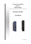
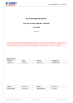
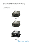
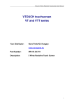
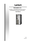
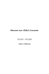
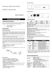
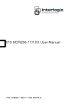
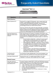
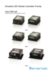
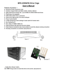
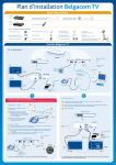
Hardened Ethernet to VDSL2 Extender User Guide Rev.1.03 Dec 2009 Revision History Industrial Ethernet to VDSL2 Extender with Wide Operating Temp. Document Release Date Revision Initials 1.00 Jun 04, 2009 First release E.C. 1.01 Aug 13, 2009 Add note for high temp environment E.C. 1.02 Oct 26, 2009 Add Pin Assignment E.C. 1.03 Dec 01, 2009 Modify Power Consumption and operating temperature for UL508 FCC Warning II E.C. This Equipment has been tested and found to comply with the limits for a Class-A digital device, pursuant to Part 15 of the FCC rules. These limits are designed to provide reasonable protection against harmful interference in a residential installation. This equipment generates, uses, and can radiate radio frequency energy. It may cause harmful interference to radio communications if the equipment is not installed and used in accordance with the instructions. However, there is no guarantee that interference will not occur in a particular installation. If this equipment does cause harmful interference to radio or television reception, which can be determined by turning the equipment off and on, the user is encouraged to try to correct the interference by one or more of the following measures: Reorient or relocate the receiving antenna. Increase the separation between the equipment and receiver. Connect the equipment into an outlet on a circuit different from that to which the receiver is connected. Consult the dealer or an experienced radio/TV technician for help. CE Mark Warning This is a Class-A product. In a domestic environment this product may cause radio interference in which case the user may be required to take adequate measures. Content Introduce.......................................................................................................................1 FEATURES .....................................................................................................................................1 PACKAGE CONTENTS ....................................................................................................................4 Hardware Description ...................................................................................................5 FRONT PANEL ...............................................................................................................................5 TOP VIEW .....................................................................................................................................6 WIRING THE POWER INPUTS..........................................................................................................7 WIRING THE FAULT ALARM CONTACT..........................................................................................7 LED INDICATORS..........................................................................................................................8 DIP-SWITCH ..................................................................................................................................9 DATA RATES AND DISTANCES ......................................................................................................1 Mounting Installation.....................................................................................................1 DIN-RAIL MOUNTING ..................................................................................................................1 WALL MOUNT PLATE MOUNTING .................................................................................................3 APPLICATION ................................................................................................................................1 Troubles shooting .........................................................................................................2 Appendix A-Pin assignment..........................................................................................3 ii Introduce The Industrial Ethernet to VDSL2 extender is long reach Ethernet module with one Ethernet port (RJ-45 connector) and one VDSL port (RJ-45 connector). It provides Ethernet and VDSL technologies to extend Ethernet over single-pair phone line by using a VDSL signal. Up to 88/49 Mbps transition bandwidth within 200m and 22/5.3 Mbps for 1km long range connections provides ultra-high performance to the pervasive telephone line network. It has the advantage of minimum installation time and minimum expense by allowing video streaming and data to share the same telephone pair without interference. Features Standard IEEE 802.3 10BASE-T IEEE 802.3u 100BASE-TX ITU-T ITU-T -G.993.1(VDSL) -G.997.1 compatible Per unit: Power1, Power2, P-Fail LED Indicators LAN port: LNK/ACT, SPD VDSL port: LNK/ACT, CO Connector 10/100TX: 1 x RJ-45 with auto MDI/MDI-X function. VDSL: 1 x RJ-45 with female Phone Jack 1 DIP1: Master, Slave switch DIP2: Impulse noise protection DIP Switch DIP3: Rate limit control DIP4: General protection 10Base-T: 2-pair UTP/STP Cat. 3, 4, 5 cable EIA/TIA-568 100-ohm (100m) Cabling 100Base-TX: 2-pair UTP/STP Cat. 5 cable EIA/TIA-568 100-ohm (100m) VDSL: Twisted-pair telephone Full VDSL2 bandwidth up to: (Down Stream / Up Stream) - 200m -> 88 / 49Mbps - 400m -> 63 / 29Mbps Performance(Based - 600m -> 46 / 18Mbps on AWG26 wires) - 800m -> 30 / 5.7Mbps - 1000m -> 22 / 5.3Mbps - 1500m -> 18 / 0.8Mbps - 2000m -> 9 / 0.5Mbps Power Power Consumption 12~48VDC , 24VAC 24 VAC, 50/60 Hz, Maximum 7.7 W, 12-48 VDC, Maximum 6 W, Class 2 -40℃ to 75℃ Operating NOTE: Temperature For use in Pollution Degree 2 Environment Maximum Surrounding Air Temperature 75°C Operating Humidity 5% to 95% (non-condensing) 2 Storage Temperature -40℃~85℃ MBTF 260895 hrs Dimensions 36.6 x 140 x 95 mm Enclosure IP-30, metal shell Safety UL508, Class 1/ Division 2 CE, FCC Class A EN61000-6-4 EN61000-6-2 EN61000-4-2 (ESD) EN61000-4-3 (Radiated RFI) EMC EN61000-4-4 (Burst) EN61000-4-5 (Surge) EN61000-4-6 (Induced RFI) EN61000-4-8 (Magnetic Field) EN61000-4-11 (Voltage Dip) EN61000-3-2 (Harmonics Current) EN61000-3-3 (Voltage Fluctuation & Flickers) Shock IEC60068-2-27 Freefall IEC60068-2-32 Vibration IEC60068-2-6 3 Package Contents Beware of which type of extender that you have purchased. And, please refer to the package content list below to verify them against the checklist. Industrial Ethernet to VDSL2 extender package contains following items. ¾ The Industrial Ethernet to VDSL2 extender ¾ User manual ¾ Block connector ¾ 2 wall mount plates and 6 screws ¾ One DIN-Rail (attached on the switch) Compare the contents of your standalone extender with the standard checklist above. If any item is damaged or missing, please contact your local dealer for service. 4 Hardware Description The Industrial Ethernet to VDSL2 extender dimension: 36.6 x 140 x 95 mm Front Panel Industrial Ethernet to VDSL2 extender The Front Panel of the Industrial Ethernet to VDSL2 extender consists of one Ethernet port, one VDSL Port, and 3 LED Indicators (Power1, Power2, P-Fail, SPD for LAN port, LNK/ACT for LAN port, CO, LNK/ACT for VDSL). 5 3 1 4 2 (1) LAN Port (3) LED (2) VDSL (4) DIP-Switch Top View The top panel of the Industrial Ethernet to VDSL2 extender is equipped one terminal block connector of two DC power inputs. 6 Top Panel of the Industrial Ethernet to VDSL2 extender Wiring the Power Inputs Please follow the steps below to insert the power wire. Insert the positive and negative wires into the V+ and V- contacts on the terminal block connector. Tighten the wire-clamp screws for preventing the wires from loosing. Wiring the Fault Alarm Contact The fault alarm contact is in the middle of terminal block connector as the picture shows below. Inserting the wires, it will detect the fault status including power failure/port link failure and form an open circuit. 7 Insert the wires into the fault alarm contact. Note: z Use Copper Conductors Only, Tighten to 5 lb in z The wire gauge for the terminal block should be in the range between 12~ 24 AWG. LED Indicators There are 7 diagnostic LEDs located on the Front panel of converter module. They provide real-time information of system and optional status. The following table provides description of the LED status and their meanings for Industrial Ethernet to VDSL2 extender. LED Power1 (Green) Power2 (Green) P-Fail (Red) Status Meaning ON Power 1 on OFF Power 1 off BLK --- ON Power 2 on OFF Power 2 off BLK --- ON Power1/Power2 is inactive OFF BLK Power1 and Power2 are both active, or no power input --- 8 ON Link up OFF Link down BLK Transmitting ON 100Mbps OFF 10Mbps BLK --- LNK/ACT for LAN (Green) Speed for LAN (Amber) Acting as Customer Premise ON Equipment (CPE) side CO (Green) OFF Acting as Central Office (CO) side BLK --- ON Link up OFF Link down BLK Negotiating, Transmitting LNK/ACT for VDSL (Green) DIP-switch The DIP-switch is used to configure operation mode in below. The default value of Dipswitch is OFF. S/W No 1 2 Feature Status Master, Slave ON switch Impulse noise protection OFF ON Description Acting as Customer Premise Equipment (CPE) side Acting as Central Office (CO) side Fast mode: Direct data transmission with latency less than 1ms. 9 Interleave mode: Provides communication OFF protection for up to 250ms impulse noise latency less than 6ms. 3 4 Rate limit control General protection ON OFF ON OFF Limit line-rate Disable: Provides up to 100Mbps/60Mbps line rate in short line. Limit line-rate Enable: Line rate limited to 50/20 Mbps. SNR 6dB: Original and Normal channel noise protection with 6dB SNR. SNR 9dB: Higher SNR margin (9dB) will result in less error with more stable VDSL link. Note: Please set DIP4 OFF when operating in harden environment. That mean will keep better performance. 10 Data Rates and Distances Performance in AWG24 Line at 6db with full rate Performance in AWG24 (Fast mode, SNR 6dB, 998 for ISDN) Distance Data Rate (Feet) (m) Downstream(Mbps) Upstream(Mbps) 0 0 93.1 54.6 250 76.19 97.1 56 500 152.39 95.3 54.1 1000 304.79 81 44.1 1500 457.19 62.9 28.9 2000 609.59 45.8 18.3 2500 761.99 34.3 7.1 3000 914.39 25.8 7.9 3500 1066.79 21.8 5.3 4000 1219.19 16.4 6.2 4500 1371.59 18.5 0.8 5000 1523.99 18.4 0.8 5500 1676.39 14.8 0.7 6000 1828.79 11.7 0.6 6500 1981.19 9.5 0.5 1 Performance in AWG24 (Fast mode, SNR 6dB, Symetric for ISDN) Distance(Feet) Data Rate (Feet) (m) Downstream(Mbps) Upstream(Mbps) 0 0 80.5 88.5 250 76.19 83.8 90.6 500 152.39 81.4 86.8 1000 304.79 63.7 64.4 1500 457.19 47.9 40.0 2000 609.59 32.3 25.7 2500 761.99 23.2 14.3 3000 914.39 17.9 16.7 3500 1066.79 15.4 13.1 4000 1219.19 12.5 8.1 4500 1371.59 19.4 0.8 5000 1523.99 15.8 0.8 5500 1676.39 12.9 0.7 6000 1828.79 10.3 0.6 6500 1981.19 7.6 0.5 2 Mounting Installation DIN-Rail Mounting The DIN-Rail is screwed on the unit when out of factory. If the DIN-Rail is not screwed on the unit, please see the pictures and follow the steps below to screw the DIN-Rail on the unit. 1. Use the screws to screw the DIN-Rail on the rear side of the unit. 2. To remove the DIN-Rail, reverse the step 1. 1 3. After the DIN-Rail is screwed on the rear side of the unit, insert the top of DIN-Rail into the track. 4. Then, lightly push the DIN-Rail into the track. 5. Check if the DIN-Rail is tightened on the track or not. 6. To remove the unit from the track, reverse steps above. 2 Wall Mount Plate Mounting Follow the steps below to mount the unit with wall mount plate. 1. Remove the DIN-Rail from the unit; loose the screws to remove the DIN-Rail. 2. Place the wall mount plate on the top & bottom side of the unit. 3. Use the screws to screw the wall mount plate on the unit. 4. Use the hook holes at the corners of the wall mount plate to hang the unit on the wall. 5. To remove the wall mount plate, reverse steps above. 3 Application r. 1 Troubles shooting Check the configuration DIP-switch. It must be setting in the same operation mode with the link partner. Select the proper Copper/Phone-line cable to construct your network. Please check that you are using the right cable. 2 Appendix A-Pin assignment z RJ-45 pin assignment The Fast Ethernet ports (RJ-45) will auto-sense for 10Base-T or 100Base-TX connections. Auto MDI/MDI-X means that the switch can connect to another switch or workstation without changing straight-through or crossover cabling. Please refer to Table-1 for RJ-45 pin assignment. Pin Number Assignment 1 Tx+ 2 Tx- 3 Rx+ 6 RxTable-1: RJ-45 Pin Assignment Note “+” and “-” signs represent the polarity of the wires that make up each wire pair. All ports on this industrial switch supports automatic MDI/MDI-X operation, users can use straight-through cables (See figures below) for all network connections to PCs or Servers, or to other switches/hubs. In straight-through cable, pins 1, 2, 3, and 6, at one end of the cable, are connected straight through to pins 1, 2, 3 and 6 at the other end of the cable. Table-2 shows the 10BASE-T/100BASE-TX MDI and MDI-X port pin-outs. 3 Pin MDI-X Signal MDI Signal 1 Receive Data plus (RD+) Transmit Data plus (TD+) 2 Receive Data minus (RD-) Transmit Data minus (TD-) 3 Transmit Data plus (TD+) Receive Data plus (RD+) 6 Transmit Data minus (TD-) Receive Data minus (RD-) Table-2: MDI/MDI-X Port Pin-outs The following figures show the cable schematic for straight-through type (Figure-1) and crossover type (Figure-2). Switch 3 TD+ 6 TD- Router / PC 3 RD+ 6 RD- 1 RD+ 2 RD- 1 TD+ 2 TD- Figure-1: Straight Through Cable Schematic Switch 3 TD+ 6 TD- Switch 3 RD+ 6 RD- 1 RD+ 2 RD- 1 TD+ 2 TD- Figure-2: Crossover Cable Schematic z PIN assignment for VDSL Port We support RJ-45 straight cable and RJ-11 2 wires straight cable too. The data use 2 wires (one pair) as below picture shows. 4 5