1
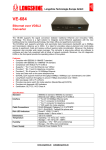
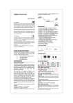
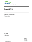
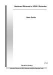
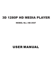
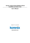
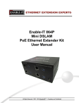
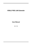
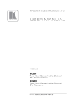
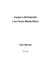
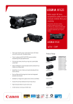
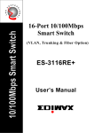
The Front Panel Coaxial LAN Converter VDSL2 Converter The Rear Panel User’s Manual Coaxial LAN Converter Dip Switch Settings Unpacking Information Thank you for purchasing the Coaxial LAN converter. Before installation, please check that your package contains the following items: 1. 2. 3. One Coaxial LAN Converter One power adapter One user’s manual Introduction General Description The Coaxial LAN Converter supports the signal conversion between traditional Ethernet and Coaxial cable technology. The device is a right solution to integrate current Ethernet application with Coaxial cable line which is existed in many old buildings, like hotel, office and apartment environment. The BNC port supports asymmetry data transmission bandwidth up to 100Mbps and transmission distance up to 900m. It is ideal for providing video-on-demand and multi-media service to apartment, hotel and campus without rewiring cable consideration. Moreover, the distance expansion also provides wide range coverage. The converter is plug-n-play without any software to configure and also fully compliant with all kinds of network protocols. Moreover, the rich diagnostic LEDs on the front-panel provide the operating status of the system. The cable specifications of the connection are listed as following: 10BASE-T, Category 3, 4 or 5 UTP/STP 100BASE-TX, Category 5 UTP/STP Coaxial line The drawing listed below is typical application for the Coaxial LAN Converter. ON OFF Pin1 Side Slave (CPE) Master (CO) Pin2 Mode Fast Interleave Pin3 Rate limit No limit 50/20 Mbps Pin4 SNR 6dB 9dB Pin1: Master, slave switch Slave (CPE): Coaxial LAN converter acts as Slave / Customer Premise Equipment (CPE) side. Master (CO): Coaxial LAN converter acts as Master / Central Office (CO) side. Pin2: Impulse noise protection Fast mode: Direct data transmission with latency less than 1 ms. Interleave mode: Provides communication protection for up to 250ms impulse noise with latency less than 6 ms. Pin3: Rate limit control No limit: Provides up to 100Mbps/50Mbps line rate in short line. 50/20 Mbps: Line rate limited to 50/20Mbps. Pin4: General protection 6dB: Original channel noise protection with 6 dB SNR. 9dB: Better channel noise protection with SNR up to 9 dB. Note: SNR (Signal Noise Rate) = Signal / Noise. Switch on this pin depends on your network demand. LEDs Definition LED Power BNC 10/100M Master Slave Status Green Off Green Blinking Green* Off Green Blinking Green* Green Off Green Off Operation The device is powered on. The device is powered off. The port is connected. Data transmitting/receiving. No valid link on this port. The port is connected. Data transmitting/receiving. The device acts as Master mode. The master mode is off. The device acts as Slave mode. The slave mode is off. * Once the converter connects to a power source, the LEDs of 10/100M blink once, and the converter begins looking for other converter automatically. During searching, the BNC LED keeps blinking; it stops blinking after success detection. Product Specifications Key Features y y y y y y y y y y y Complies with IEEE802.3 10BASE-T standard Complies with IEEE802.3u 100BASE-TX standard Supports 1 * BNC port for Ethernet over coaxial line Provides 2 * RJ-45 ports for 10/100Mbps Ethernet Provides 1 * Dip Switch for mode selection Data transmit on coaxial line BNC port supports maximum throughput 60Mbps/100Mbps (upstream /downstream) over 1000ft (400m) Long-reach throughput is around 70Mbps downstream over 3000ft (9000m) Mini size design (120 x 75 x 25mm) Provides rich diagnostic LED indicators External power adapter Standard Interface LED indications Emission Temperature Humidity IEEE802.3 standard IEEE802.3u standard Ethernet over coaxial cable 2 * RJ-45 10/100Mbps Ethernet ports 1 * BNC connector for Ethernet over Coaxial cable 1 * DIP switch for selective transmission and Slave/Master modes Power*1, BNC*1, LAN*2, Master mode*1, Slave mode*1 FCC Class A, CE, VCCI Class A Operating -- 00- 400C (32° ~ 104°F) Storage -- -100- 700C (14° ~ 158°F) Operating -- 10% ~ 90% (non-condensing) Storage – 5%~95% (non-condensing) VDSL2 Converter Unpacking Information Thank you for purchasing the Ethernet over VDSL2 converter. Before installation, please check that your package contains the following items: 1. 2. 3. 4. One One One One Ethernet over VDSL2 converter power adapter telephone line user’s manual Introduction General Description The VDSL2 Converter supports the signal conversion between traditional Ethernet and innovative VDSL2 technology. The device is a right solution to integrate current Ethernet application with the new building phone line networking technology, like hotel, office and apartment environment. The EoVDSL2 port supports symmetry and asymmetry data transmission bandwidth up to 100Mbps and transmission distance up to 1500m. It is ideal for providing video-on-demand and multi-media service to apartment, hotel and campus without rewiring cable consideration. Moreover, the distance expansion also provides wide range coverage. The converter is plug-n-play without any software to configure and also fully compliant with all kinds of network protocols. Moreover, the rich diagnostic LEDs on the front-panel provide the operating status of the system. The cable specifications of the connection are listed as following: 10BASE-T, Category 3, 4 or 5 UTP/STP 100BASE-TX, Category 5 UTP/STP Ethernet over VDSL2, Twisted-pair telephone wires The drawing listed below is a typical application for the Ethernet over VDSL2 converter. Master Phone line Slave Telephone Dip Switch Settings ON OFF Pin1 Side Slave (CPE) Master (CO) Pin2 Mode Fast Interleave Pin3 Rate limit No limit 50/20 Mbps Pin4 SNR 6dB 9dB Pin1: Master, slave switch Slave (CPE): EoVDSL2 converter acts as Slave / Customer Premise Equipment (CPE) side. Master (CO): EoVDSL2 converter acts as Master / Central Office (CO) side. Pin2: Impulse noise protection Fast mode: Direct data transmission with latency less than 1 ms. Interleave mode: Provides communication protection for up to 250ms impulse noise with latency less than 6 ms. Pin3: Rate limit control No limit: Provides up to 100Mbps/50Mbps line rate in short line. 50/20 Mbps: Line rate limited to 50/20Mbps. Pin4: General protection 6dB: Original channel noise protection with 6 dB SNR. 9dB: Better channel noise protection with SNR up to 9 dB. Note: SNR (Signal Noise Rate) = Signal / Noise. Switch on this pin depends on your network demand. LEDs Definition LED Status Green Off Green VDSL Blinking Green* Off Green 10/100M Blinking Green* Green Master Off Green Slave Off Power Operation The device is powered on. The device is powered off. The port is connected. Data transmitting/receiving. No valid link on this port The port is connected. Data transmitting/receiving. The device acts as Master mode. The master mode is off. The device acts as Slave mode. The slave mode is off. * Once the converter connects to a power source, the LEDs of 10/100M blink once, and the converter begins looking for other converter automatically. During searching, the VDSL LED keeps blinking; it stops blinking after success detection. Product Specifications Key Features y y y y y y y y y y y y y Complies with IEEE802.3 10BASE-T standard Complies with IEEE802.3u 100BASE-TX standard Compliance with VDSL2 ITU-T G.993.2 Supports 1 * RJ-11 port for Ethernet over VDSL2 Provides 1 * RJ-11 port for telephone connection Provides 2 * RJ-45 ports for 10/100Mbps Ethernet Provides 1 * Dip Switch for mode selection Voice and Data work on the same telephone line EoVDSL2 port supports maximum bandwidth 100Mbps/50Mbps (downstream /upstream) over 1000ft (300m) Long Reach VDSL2 performance around 17Mbps downstream over 5000ft (1500m) Mini size design (120 x 75 x 25mm) Provides rich diagnostic LED indicators External Power Adapter Standard Interface LED indications Emission Temperature Humidity IEEE802.3 standard IEEE802.3u standard Ethernet over VDSL2 VDSL2 ITU-T G.993.2 2 * RJ-45 10/100Mbps Ethernet ports 1 * RJ-11 connector for EoVDSL2 1 * RJ-11 connector for telephone connection 1 * DIP switch for selective transmission modes Power*1, VDSL*1, LAN*2, Master mode*1, Slave mode*1 FCC Class A, CE, VCCI Class A Operating -- 00- 400C (32° ~ 104°F) Storage -- -100- 700C (14° ~ 158°F) Operating -- 10% ~ 90% (non-condensing) Storage – 5%~95% (non-condensing) The Front Panel FCC Certifications This Equipment has been tested and found to comply with the limits for a Class A digital device, pursuant to part 15 of the FCC Rules. These limits are designed to provide reasonable protection against harmful interference when the equipment is operated in a commercial environment. This equipment generates, uses, and can radiate radio frequency energy and, if not installed and used in accordance with the instruction manual, may cause harmful interference to radio communications. Operation of this equipment in a residential area is likely to cause harmful interference in which case the user will be required to correct the interference at his own expense. The Rear Panel This device complies with Part 15 of the FCC Rules. Operation is subject to the following two conditions: (1) this device may not cause harmful interference, and (2) this device must accept any interference received; including interference that may cause undesired operation. CE Mark Warning This equipment complies with the requirements relating to electromagnetic compatibility, EN 55022 Class A for ITE, the essential protection requirement of Council Directive 89/336/EEC on the approximation of the laws of the Member States relating to electromagnetic compatibility. Company has an on-going policy of upgrading its products and it may be possible that information in this document is not up-to-date. Please check with your local distributors for the latest information. No part of this document can be copied or reproduced in any form without written consent from the company. Trademarks: All trade names and trademarks are the properties of their respective companies. Copyright © 2008, All Rights Reserved.