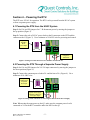
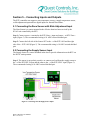
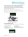
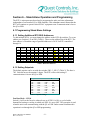
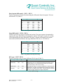
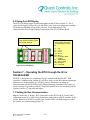
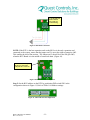
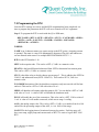
1
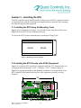
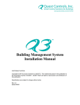
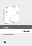
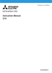
RTU Controller User’s Manual COPYRIGHT NOTICE Copyright © 2007 -2011 by Quest Controls Inc (QUEST). The material discussed in this publication is the proprietary property of QUEST. QUEST retains all rights to reproduction and distribution of this publication. Specifications are subject to change without notice. RTU Controller User Manual Rev 3.2 6/13/11 Table of Contents SECTION 1 – INTRODUCTION 2 SECTION 2 – PRODUCT DESCRIPTION 2.1 FEATURES AND BENEFITS 2.2 SPECIFICATIONS 2 2 3 SECTION 3 – INSTALLING THE RTU 3.1 INSTALLING THE RTU USING THE MOUNTING TRACK 3.2 INSTALLING THE RTU DIRECTLY ONTO HVAC EQUIPMENT 4 4 4 SECTION 4 – POWERING THE RTU 4.1 POWERING THE RTU FROM THE HVAC SYSTEM 4.2 POWERING THE RTU THROUGH A SEPARATE POWER SUPPLY 5 5 5 SECTION 5 – CONNECTING INPUTS AND OUTPUTS 5.1 CONNECTING THE ZONE SENSOR WITH SLIDE ADJUSTMENT INPUT 5.2 CONNECTING THE SUPPLY SENSOR INPUT 5.3 CONNECTING THE FAN AND AIR CONDITIONING MONITORING INPUT 5.4 CONNECTING HVAC OUTPUTS 6 6 6 7 7 8 8 8 8 10 SECTION 6 – STAND ALONE OPERATION AND PROGRAMMING 6.1 PROGRAMMING STAND ALONE SETTINGS 6.1.1 SETTING ADDITIONAL RTU BUS ADDRESSES 6.1.2 SETTING SETPOINTS 6.2 USING THE LED DISPLAY SECTION 7 – OPERATING THE RTU THROUGH THE Q3 OR TELSEC ESB 7.1 SETTING UP BUS COMMUNICATION 7.2 PROGRAMMING THE RTU 10 10 13 SECTION 8 –TROUBLESHOOTING, TECHNICAL SUPPORT AND SERVICE 8.1 TROUBLESHOOTING 8.1.1 COMMUNICATION ERRORS 8.1.2 LED ERRORS 8.2 TECHNICAL SUPPORT AND SERVICE 8.3 WARRANTY 15 15 15 16 16 17 RTU Controller User Manual Rev 3.2 6/13/11 -1- Section 1 – Introduction Congratulations on your purchase of the RTU Controller for HVAC Systems. The RTU Controller is a stand-alone and network-capable specific purpose controller designed to monitor and control air conditioning systems in small to medium size buildings and remote sites. The RTU can be networked with both the Q3™ Building Management System and TELSEC ESB Controller. This User’s Manual is intended to provide the information needed to install, set up, program, and operate RTU boards Rev E and higher. If you are using the RTU in conjunction with the Q3 Building Management System or TELSEC ESB Controller, you may want to refer to their operation and programming manuals for options available when communicating with the RTU. Please contact us at Quest if you have product questions or suggestions to improve this User’s Manual. Section 2 – Product Description The RTU is a stand-alone intelligent controller that monitors and controls any HVAC systems. Up to 32 RTU controllers can be networked to the Q3 or TELSEC ESB to provide a cohesive and effective building energy management system. 2.1 Features and Benefits The RTU offers features and benefits that make it the ideal choice for managing the HVAC systems of small to medium size buildings. Complete Digital Control: The RTU provides direct digital control over all environmental control functions. This ensures complete HVAC automation resulting in reduced maintenance costs, reduced energy consumption and increased efficiency. Networking Capabilities: Up to 16 RTUs can be easily networked into the Q3 or TELSEC ESB system to control multiple air-conditioning for fan, cooling, heating, and economizer. In addition, the RTU will monitor zone and supply air temperatures, fan running, and filter clogging. Intelligent Operation: The RTU is microprocessor based and is programmed to make real-time adjustments independent of a networked Q3 or ESB controller. This redundant control ensures the continued operation of critical HVAC equipment in the event network local communication is lost. LED Display: Numeric LED displays show the status of zone and supply air temperature sensors. Additional LEDs denote control, alarm, and communication status, making this information easily accessible and convenient for maintenance personnel. Zone Temperature Control: Provides precise control of the HVAC to maintain desired zone temperature, while reducing operating expenditures and extending the life of critical operating equipment. RTU Controller User Manual Rev 3.2 6/13/11 -2- 2.2 Specifications Part Number: 130440 Digital Outputs (6): Fan, cool 1, cool 2, heat 1, heat 2, economizer Analog Ouputs (1): Output range 0-20 mA Analog Inputs (3): Zone sensor, supply sensor, and setpoint adjustment sensor Digital Inputs (2): Fan status and air conditioning failure Status LEDs: Output status, power, network transmit & receive, communication fail, heartbeat Power: 24VAC or 24VDC @ 0.2 amps LED: Readout with 7 segment display for status of zone and supply temperature sensors Network Interface: RS-485 Sensor Accuracy: ±1°F (±05°C) over full range Environmental: Operating Temp -40° to 185°F (-40° to +85°C) 0-95% RH noncondensing Mounting: TDK Snap Track (outdoor installation requires the RTU™ to be in a NEMA 4 Enclosure) Dimensions: 3" H x 6" W x 1.3" D (76mm H x 152mm W x 33mm D) Weight: 1 lb (454g) Warranty: One (1) year RTU Controller User Manual Rev 3.2 6/13/11 -3- Section 3 – Installing the RTU The RTU controller can be installed inside a rooftop unit or on HVAC equipment located in a protected area using the mounting track supplied with the controller or by mounting the controller directly onto equipment. 3.1 Installing the RTU Using the Mounting Track Step 1: Secure mounting track (Figure 1) to selected location using sheet-metal screws. Step 2: Insert the RTU circuit board and press down. To release the RTU from the mounting track, spread edge of Snap Track. Figure 1: Mounting Track for the RTU 3.2 Installing the RTU Directly onto HVAC Equipment Step 1: To mount the RTU onto HVAC equipment, drill four 5/32” diameter holes in a rectangular pattern measuring 2 51/64” (71mm) by 5 19/32” (142mm) (Figure 2). Step 2: Use appropriate hardware and standoffs (#6 hardware) to keep the back of the RTU controller from contacting the surface of the equipment on which it is being mounted. 19 5 32 51 2 64 Figure 2: Location of Mounting Holes RTU Controller User Manual Rev 3.2 6/13/11 -4- Section 4 – Powering the RTU The RTU uses 24VAC for operation. The RTU can be powered from the HVAC system or from a separate power supply. 4.1 Powering the RTU from the HVAC System Step 1: Set J1A and J1B jumpers for C / R thermostat power by moving the jumpers to the up position (Figure 3). Step 2: Connect the red or 24VAC power leads to the R connector on the RTU and the common to the C (Figure 3). Use a minimum of 18 AWG wire for powering and control. Jumpers J1A and J1B to HVAC Power Input Power Connection Using HVAC Transformer Figure 3: Settings & Connections for Power the RTU from the HVAC 4.2 Powering the RTU Through a Separate Power Supply Step 1: Set J1A and J1B jumpers for 24+/24- input connectors by moving the jumpers to the down position (Figure 4). Step 2: Connect the common power lead to 24- and the hot to 24+ (Figure 4). Use a minimum of 18 AWG wire. Jumpers J1A and J1B to Q3 or Separate Power Input From the Q3 or Separate Power Supply, Maintain Commons on the Negative Inputs Figure 4: Settings and Connections for Powering the RTU from the Power Supply Note: When using the same power as the Q3, make sure the common power lead is connected to 24- on the RTU controller and to the NEG on the Q3. RTU Controller User Manual Rev 3.2 6/13/11 -5- Section 5 – Connecting Inputs and Outputs The RTU controller can support a zone temperature sensor, a supply temperature sensor, a slide adjustment input and two digital inputs for fan and filter alarms. 5.1 Connecting the Zone Sensor with Slide Adjustment Input The Zone Sensor is a sensor mounted in the effective heat/cool area serviced by the HVAC unit controlled by the RTU. Step 1: Connect sensor + terminal to the RTU Zone + input and sensor – to RTU Zone – input (Figure 5). The recommended wiring is 18 AWG twisted shielded pair. Step 2: Connect the left side of the Sensor SET to the + of the RTU ADJ and the right side of the – RTU ADJ (Figure 5). The recommended wiring is 18 AWG twisted shielded pair. 5.2 Connecting the Supply Sensor Input The Supply Sensor is a sensor mounted in the duct to provide information to the RTU on the HVAC unit operation. Step 1: The sensor is not polarity sensitive so connect one lead from the supply sensor to the + of the RTU SPLY input and the other to the – of the RTU SPLY input (Figure 5). The recommended wiring is 18 AWG twisted shielded pair. Figure 5: Connecting Zone & Supply Sensor Input RTU Controller User Manual Rev 3.2 6/13/11 -6- 5.3 Connecting the Fan and Air Conditioning Monitoring Input The digital fan input is designed to connect to a current transducer monitoring fan operation. Filter airflow sensors mounted on either side of the filter provide filter status. If airflow is sensed on one side of the filter and not the other, the RTU will consider the filter clogged and send the appropriate alarm. Step1: Connect the FAN input to fan motor current transducer (Figure 6). Step 2: Connect the Filter airflow Sensor or AC fail contacts to the DI input (Figure 6). Note: The negative (-) terminal is common for both inputs. FAN Current Sensor Filter Airflow Sensor Duct Filter Figure 6: Connecting Fan & Filter Input 5.4 Connecting HVAC Outputs Connections to the HVAC equipment are industry standard as with any thermostat (Figure 7). C: 24VAC Control Common R: 24VAC Control Voltage G: Fan Control Y1: First Stage Compressor (Cooling) Y2: Second Stage Compressor (Cooling) W1: First Stage Heat W2: Second Stage Heat NO: Normally Open Economizer Control NC: Normally Closed Economizer Control Figure 7: HVAC Control Points RTU Controller User Manual Rev 3.2 6/13/11 -7- Section 6 – Stand Alone Operation and Programming The RTU is microprocessor-based and is programmed to make real-time adjustments independent of a networked Q3 or ESB controller. This redundant control means that the RTU will continue to operate critical HVAC equipment even if communication is lost to the Q3 or ESB. 6.1 Programming Stand Alone Settings 6.1.1 Setting Additional RTU BUS Addresses To add multiple RTUs, you must change the address on the RTU dip switches. To set an address, use switches 1-4 on SW1 (Table 1). These are the address bits of the RTU. The base address is 20 and the range of possible addresses is 20-2F for RTU controllers 1 through 16. RTU # 1 2 3 4 5 6 7 8 Address 20 21 22 23 24 25 26 27 SW 1.1 OFF OFF OFF OFF OFF OFF OFF OFF SW 1.2 OFF OFF OFF OFF ON ON ON ON SW 1.3 OFF OFF ON ON OFF OFF ON ON SW 1.4 OFF ON OFF ON OFF ON OFF ON RTU # 9 10 11 12 13 14 15 16 Address 28 29 2A 2B 2C 2D 2E 2F SW 1.1 ON ON ON ON ON ON ON ON SW 1.2 OFF OFF OFF OFF ON ON ON ON SW 1.3 OFF OFF ON ON OFF OFF ON ON SW 1.4 OFF ON OFF ON OFF ON OFF ON Table 1: RTU Bus Addresses 6.1.2 Setting Setpoints The default setpoint can be set with the switches SW1.5 - SW1.7 (Table 2). The base is 70F. Each bit moves the setpoint 1 degree. The RTU will use this setting if communications is lost to the Q3 or ESB. Setpoint SW1.5 SW1.6 70F OFF OFF 71F OFF OFF 72F OFF ON 73F OFF ON 74F ON OFF 75F ON OFF 76F ON ON 77F ON ON Table 2: Setpoint Settings SW1.7 OFF ON OFF ON OFF ON OFF ON Fan Run Mode – SW1.8 Switch 1.8 will set the fan to be either always on if SW1.8 is ON; or cycled with a demand for heating or cooling in which case SW1.8 is set to OFF. This operation is used when the unit is not communicating with the Q3 or ESB. Under normal conditions this operation is set through the Q3 or ESB programming. RTU Controller User Manual Rev 3.2 6/13/11 -8- Heat Setpoint Differential – SW2.1 - SW2.3 The heat setpoint is calculated by subtracting this differential from the setpoint. The base differential is 2F (Table 3). Differential SW2.1 SW2.2 SW2.3 2F OFF OFF OFF 3F OFF OFF ON 4F OFF ON OFF 5F OFF ON ON 6F ON OFF OFF 7F ON OFF ON 8F ON ON OFF 9F ON ON ON Table 3: Heat Setpoint Differential Settings Stage Differential – SW2.4 - SW2.6 The RTU provides two stages of heating and cooling. The stage setpoint is determined by applying the stage differential to the appropriate setpoint. The stage 2 setpoint for cooling is the setpoint plus the stage differential. The stage 2 setpoint for heating is the setpoint minus the heat differential minus the stage differential. The base is 2°F (Table 4). Differential 2F 3F 4F 5F 6F 7F 8F 9F SW2.4 OFF OFF OFF OFF ON ON ON ON SW2.5 OFF OFF ON ON OFF OFF ON ON SW2.6 OFF ON OFF ON OFF ON OFF ON Table 4: Stage Differential Setpoint Settings RTU type – SW2.7.SW2.8 The RTU provides a way to control different HVAC types (Table 5). RTU Type Standard AC Heat Pump SW2.7 OFF OFF SW2.8 OFF ON Heat Pump 2 ON OFF Gas Heat ON ON RTU Controller User Manual Rev 3.2 6/13/11 Description Standard DX air conditioning system with aux. heat Compressor (cool 1) on when call for heating and heating stage 1 is on for heating. Use O terminal instead of W1 for reversing valves that energize with call for cooling. Two stage heat pump. Y1 turns on compressor 1 and Y2 turns on compressor 2. Use W1 or O terminal for reversing valve control. Heat comes on without call for FAN. Assumes the RTU internally will turn on supply fan based on supply temperature Table 5: RTU Settings -9- 6.2 Using the LED Display The RTU will display status of inputs and outputs on the LED bar (Figure 8). The Z (zone) and S (supply) LEDs will cycle and display their respective temperature readings. The heartbeat will blink as long as the processor is operating properly. The communication fail will light if the bus connection to the Q3 or ESB has failed. Z or S for Zone Temp or Supply Temp will be lit to indicate which temp is being displayed. The LED bar displays the status of inputs and outputs. The input/output is on when lit: G: Y1: Y2: W1: W2: EC: Fan Cool 1 Cool 2 Heat 1 Heat 2 Economizer Mode Enabled FN: Fan Running DI: Filter Clogged HB: Heartbeat CF: Comm Fail Figure 8: The LED Display Section 7 – Operating the RTU through the Q3 or TELSEC ESB The RTU is designed to be networked to the Q3 controller and the TELSEC ESB controller. Communication with the Q3 or ESB is done over the BUS and the operational parameters are set through the Q3 or ESB. For more information on setting up communication with the Q3/ESB or Q3/ESB programming commands refer to the User Manual and the Programming Manual. Program examples below are based on Q3/ESB systems with Rev 2.3 firmware and higher 7.1 Setting Up Bus Communication Step 1: Connect the A, B and C BUS connections on the RTU to the A, B and C BUS connections on the Q3 or ESB. Daisy-chain these connections to all RTU modules in the facility. Note: Once the BUS is enabled, the T and R LEDs will flash (red/green) when the systems are communicating (Figure 9). RTU Controller User Manual Rev 3.2 6/13/11 - 10 - T and R LEDs will flash to indicate the systems are communicating. Figure 9: RTU BUS Connection NOTE: If the RTU is the last expansion card on the BUS or is the only expansion card connected to the system, ensure that the jumper on J5 is set to the right to jump pins 1&2. This enables the end of line resistor. The Jumper on J5 should be to the left (pin 2&3) when the RTU Board is in the middle of a network chain. (Figure 10). Bus Termination Jumper J5 shown as last in line with pins 1& 2 connected. Figure 10: BUS Termination Jumper J5 Step 2: Set the BUS address on the RTU by positioning DIP-switch SW1 in the configuration shown in Figure 11, Refer to Table 1 for address settings. Figure 11: SW1 DIP Switch Configuration RTU Controller User Manual Rev 3.2 6/13/11 - 11 - Step 3: Define the RTU address to the Q3 or ESB by entering the following command in the Q3/ESB programming: FORMAT: DEF <Name=> BUS# EXAMPLE: DEFINE OFFICE=BUS 16 CONTROLLER RESPONSE: OK A standard addressing scheme comes pre-loaded in the RTU and can be accessed using the REVIEW command. Step 4: To review all RTUs connected and defined in the system and their BUS addresses enter, ;REV BUS A list of all BUS modules connected to the system will be displayed with their BUS address (Figure 12). In the list below, you can see that an RTU has been added to BUS.16 using address 20. The simple command of DEF BUS.16 told the system that the RTU was connected. BUS 16 is the first location for RTU controllers. # NAME ADDR PRESENT STATE ERRORS ======================================== 1. BUS001 00 NO OK 0 2. BUS002 01 NO OK 0 3. BUS003 02 NO OK 0 4. BUS004 03 NO OK 0 5. BUS005 04 NO OK 0 6. BUS006 05 NO OK 0 7. BUS007 60 NO OK 0 8. BUS008 61 NO OK 0 9. BUS009 62 NO OK 0 10. BUS010 63 NO OK 0 11. BUS011 64 NO OK 0 12. BUS012 65 NO OK 0 13. BUS013 66 NO OK 0 14. BUS014 70 NO OK 0 15. BUS015 71 NO OK 0 16. OFFICE 20 YES OK 0 Figure 12: RTUs with BUS Address RTU Controller User Manual Rev 3.2 6/13/11 - 12 - 7.2 Programming the RTU Once the RTU settings are correct, and the BUS assignment has been completed, it is time to program the parameters the RTU will use to control to HVAC equipment. Step 1: To program the RTU to work with the Q3 or ESB enter, DEF [NAME=] RTU.# <SETP> <HEAT D> <STG 2> <FAN MODE> <SHDN> <ECON> <AOP> <LOG INT> <ZALMH> <ZALML> <DIG1ALM> <DIG2ALM> <ACMON> WHERE: NAME is an 8-character name you want to assign to the RTU point. (Assigning a name is optional. The name is a max of 8 alphanumeric characters. Plus,#,&, and underscore., are not allowed in the name. For example DEF FRNTROOM=RTU.2…) RTU# is the RTU number 1-16. SETP is the setpoint value. This can be a SPT.#, VAR.# or a numeric value. HEAT D is the heat differential subtracted from SETP to determine heat turn on point. This can be a SPT.#, VAR.# or a numeric value. STG 2 is the delta value to decide when to turn on stage 2. This is added to the SETP for COOL 2 and subtracted from (SETP - HEAT D). This can be a SPT.#, VAR.# or numeric value. FAN MODE determines if the fan should run constant or only turn on with call for heat and cool. This can be a SPT or VAR with value of 0 or 1. SHDN will shutdown all outputs when this point is ON. You can define a SPT or VAR with value of 1 or 0. A value of OFF will disable the shutdown mode. ECON will enable the use of the economizer. This value can be a SPT, VAR or value of 1 or 0. A value of 1 will enable econ mode, which acts as stage 1 cooling. AOP is the analog output value. This can be a SPT.#, VAR.#, or a number from 0 to 100 and will be the percentage output of the AOP, i.e. 0 to 100% of the range. LOG INT is the logging interval in minutes between log entries. Each log entry will have zone temp, supply temp and current mode of RTU. To retrieve log use REV LOG RTU. RTU Controller User Manual Rev 3.2 6/13/11 - 13 - ZALMH is the amount added to the SETP value to determine the high temp alarm. This value can be a numeric, VAR.#, or SPT.#. The delay time in minutes before alarming can also be set (ON SPT.23 20). The value can also be OFF for no alarm. ZALML is the amount subtracted from the SETP value to determine the low temp alarm. This value can be a numeric, VAR.#, or SPT.#. The delay time in minutes before alarming can also be set (ON SPT.24 20). The value can also be OFF for no alarm. DIG1ALM is the Fan fail alarm. If set to ON, then when the fan is running and the input is off for the delay time, the RTU will generate a MJ alarm condition. This will clear when the fan is running and the feedback digital is on. DIG2ALM is the Filter clogged alarm. If set to ON, then when the fan is running and the input is on for the delay time, the RTU will generate a MN alarm condition. This will clear when the fan is running and the feedback digital is off. <ACMON> is the value to determine high supply air (HVAC TROUBLE) alarm when there is a call for cooling. This value can be a numeric, VAR.#, or SPT.#. The delay time in minutes from 1-99 before the alarm is active. OFF instead of (ON VALUE Delay) for no alarm. Once the alarm occurs, the system must see a call for cooling and the supply air below the setting for one minute to clear the alarm. For example, if you use enter the following values, DEFINE SETPOINT = VAR.13 72 DEFINE HEATDLTA = VAR.14 7 DEFINE STG2DLTA = VAR.15 2 DEFINE ECONMODE = VAR.16 0 DEFINE FAN_RUN = SPT.22 1 DEFINE HITEMPZN = SPT.23 8 DEFINE LOTEMPZN = SPT.24 12 DEFINE SPLY_AIR = SPT.25 65 DEF HVAC_Z1 = RTU.1 VAR.13 VAR.14 VAR.15 SPT.22 OFF VAR.16 OFF 15 ON SPT.23 20 ON SPT.24 20 ON ON SPT.25 15 The RTU will use VAR.13 for the base setpoint, VAR.14 for the heat delta, VAR.15 for the stage delta, SPT.22 for the fan run (0,1), VAR.16 for economizer mode, OFF = AOP not being used, ON SPT.23 20 for setting the high temp alarm on with the value SPT.23 and a delay of 20 minutes, ON SPT.24 20 for setting the low temp alarm on with the value SPT.24 and an alarm after 20 minutes, ON for fan run and ON for filter alarm. The air conditioning trouble alarm will be sent when the AC has been running for 15 minutes and the supply temperature is still greater than 65 degrees (spt.25). RTU Controller User Manual Rev 3.2 6/13/11 - 14 - You do not have to use SPTs or VARs, you can program the RTU with hard values such as: DEF HVAC_1 = RTU.1 72 72 ON OFF OFF OFF 15 ON 8 20 ON 12 20 ON ON 65 15 But this limits the Q3/ESB’s ability to make changes to the parameters inside the program. By using SPTs and or VARs, the Q3/ESB can be programmed to change the value of the setpoint or variable based on time, or various other conditions. Section 8 –Troubleshooting, Technical Support and Service 8.1 Troubleshooting The following section is designed to help you isolate the most likely system malfunctions that may occur. For additional help, contact Quest’s Technical Support and Service Center. 8.1.1 Communication Errors PROBLEM The Zone or Supply sensor is not reading. SOLUTION Verify wiring for each sensor. The display will show if the sensor has a short (SSE) or an open (OSE) to assist in troubleshooting the wiring. PROBLEM The RTU board won’t turn on. SOLUTION Verify the jumper switches for the power options are in the proper location for how you are powering the system. PROBLEM The System won’t communicate on the BUS. SOLUTION Verify you set the proper address on the switches. Make sure the address is defined in the Q3 or ESB. Verify the wiring between the main controller and the RTU is correct. RTU Controller User Manual Rev 3.2 6/13/11 - 15 - 8.1.2 LED Errors PROBLEM The CF LED on constantly. NOTE: CF stands for communication fault. The CF light will come on after 1 minute of no BUS activity for the address. SOLUTION Verify the address settings and that the Q3 or ESB has the address defined properly. 8.2 Technical Support and Service For questions regarding technical support, service, or repair of a product, contact us at: Quest Controls 208 9th Street Dr. West Palmetto, FL 34221 Tel: 941-729-4799 To return defective products in or out of warranty, you must have an RMA#. To get an RMA#, call 941-723-4112. For more information about our test and repair center, or about customer support services, visit our website at www.questcontrols.com. RTU Controller User Manual Rev 3.2 6/13/11 - 16 - 8.3 Warranty QUEST warrants products of its manufacture to be free from defects in design, workmanship and material under normal and proper use and service for a period of 12 months starting upon shipment from the QUEST factory, with the exception of Software noted below. Products not manufactured by QUEST will have a 90-day warranty. Software is warranted to conform to QUEST's Software Product Description applicable at the time of order. QUEST's sole obligation hereafter shall be to remedy any nonconformance of the software to the Software Product Description during the 90-day period following delivery. This warranty shall not apply to fuses, batteries, or any product or parts subjected to misuse, neglect, accident, Acts of God, or abnormal conditions of operation. QUEST agrees to repair or replace, at the place of manufacture and without charge, all parts of said products that are returned to the QUEST factory within the warranty period, provided the warrantor’s examination discloses to its satisfaction that the product was defective and that the equipment has not been altered or repaired other than with QUEST's authorization and by its approved procedures. Repair or replacement of QUEST products does not extend the original warranty period. A product or board may be deemed beyond repair if QUEST determines that it has been subject to misuse, improper maintenance, negligence or accident, damaged or had its serial number or any part thereof altered, defaced or removed. If the failure has been caused by misuse, neglect, accident, or abnormal conditions of operation, or if the warranty period has expired, repairs will be billed at a nominal cost. This warranty is in lieu of all other warranties expressed or implied, including but not limited to any implied warranty of merchantability, fitness, or adequacy for any particular purpose or use. In no event shall QUEST be liable for any special, incidental, or consequential damages, whether in contract, tort, or otherwise. RTU Controller User Manual Rev 3.2 6/13/11 - 17 -