1
US 20050034160A1
(19) United States
(12) Patent Application Publication (10) Pub. No.: US 2005/0034160 A1
Kim et al.
(43) Pub. Date:
(54) METHOD AND SYSTEM FOR
(30)
Feb. 10, 2005
Foreign Application Priority Data
CONTROLLING PERIPHERAL DEVICES
CONNECTED TO A VIDEO DEVICE
Aug. 9, 2003
(JP) ............................ .. 1020030055230
Publication Classi?cation
(75) Inventors: Yong-jun Kim, Yongin-si (KR);
J ae-kwon Kim, SuWon-si (KR);
(51)
(52)
Hyo-dae Kim, SuWon-si (KR);
Yu-seong J eon, SuWon-si (KR);
J ong-Wook Park, Seoul (KR); Eu-gene
Choi, Seoul (KR); Sung-hee Kim,
Seoul (KR); Young-mi Kang, Yongin-si
(KR)
Int. c1.7 ............................. .. H04N 7/18; H04N 7/16
Us. 01. .......................... .. 725/80; 725/147, 725/149,
725/74
(57)
ABSTRACT
A method and apparatus for effectively performing optimal
connection con?guration by recognizing the connection
status betWeen a video device and external peripheral
Correspondence Address:
devices. The method for identifying predetermined periph
SUGHRUE MION, PLLC
2100 PENNSYLVANIA AVENUE, N.W.
eral devices connected to a video device over serial com
SUITE 800
munication control lines, includes, transmitting a command
WASHINGTON, DC 20037 (US)
to establish connection of a current peripheral device having
no given device ID to its upper peripheral device among the
(73) Assignee: SAMSUNG
ELECTRONICS
CO.,
predetermined peripheral devices, and transmitting a com
mand to disconnect a connection to its loWer peripheral
LTD.
(21) Appl. No.:
10/913,468
device; requesting unique device identi?cation information
to the predetermined peripheral devices; receiving a
(22) Filed:
Aug. 9, 2004
response to the request from the current peripheral device;
and giving a device ID to the current peripheral device.
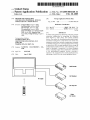
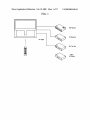
DVD-Combo
AV-Receiver
l
AV Cable
Set Top Box
Other
AV Device
Patent Application Publication Feb. 10, 2005 Sheet 1 0f 17
US 2005/0034160 A1
FIG. 1
DV m.c0 b0
AV-Receiver
AV Cable
w T.w mX
Other
AV Device
Patent Application Publication Feb. 10, 2005 Sheet 2 0f 17
US 2005/0034160 A1
FIG. 2
230
240
k’\
N
- ---------- -->
control unit
;
5
220
E
i
k’\
pa‘iket
:
generatmg umt
_
i
‘ """" "> control unit
'
E
5
210
f‘)
t
:
peripheral device -
:
\Ix
E
E
5
s
s
V
V
~"-
AV signal
200
100
-
packet transcelver
‘
E
1 """""""""""" "g
5
word :
140
r"
17o
Y
&---->
. -------- m‘
\,\
N
unit
.d J‘?
VI
90
evlce
-——
-
120
packet
E generating unit
E
A
130
Y
E
control unit
< ---- -->
‘
Y
"3 generating
-
r‘)
:
S
S
1
110
.
transceiver
260
buffer
é
E
memory unit
3
v
packet transceiver
‘
a
r4250
buffer
E
E
Y
4
umt
E 5
:
tgxssége'gvaér
mm?”
i‘ i
'
270
=
k’\
4-->_
display unit
160
N
150
r*-’
9m?“
.
generatmg unlt
Patent Application Publication Feb. 10, 2005 Sheet 3 0f 17
US 2005/0034160 A1
FIG. 3A
Communication
Control Line
_________________________ “
/
\
‘
DVD-Combo
AV-Receiver
AV Cabie
I
Set Top Box
Other
AV Device
FIG. 3B
310
Application
Protocol APi
1394 or UART device driver
V‘J
N320
“i330
340
1394 or UART hardware
A’
Patent Application Publication Feb. 10, 2005 Sheet 4 0f 17
US 2005/0034160 A1
FIG. 3C
0 Microp'rocés'sor’
or CPU
1394
1394 HUB
1394 1394 connection line
1
1394
1
1394 connection line 1394
_l
Micicprocessor
Microprocessor
Microprocessor
or CPU
or CPU
or CPU
Avdev‘icei
AV name:
AV deviceii
Patent Application Publication Feb. 10, 2005 Sheet 5 0f 17
US 2005/0034160 A1
FIG. 3D
TV
Microprocessor
or CPU
1394
1394
1394
connection line
1394
1394
1394
connection line
1394
1394
1394
1394
Microprocessor
Microprocessor
Microprocessor
or CPU
or CPU
or CPU
AV device 1
AV device 2
AV device 3
Patent Application Publication Feb. 10, 2005 Sheet 6 0f 17
US 2005/0034160 A1
TV
Microprocessor
or CPU
UART
RS-23‘2C‘ cable
UART1
UART2
Rs-232c cable
UART1
UARTZ
‘I ’
UART1
UART2
Microprocessor
Microprocessor
Microprocessor
or CPU
or CPU
or CPU
AV device 1
AV device 2
AV device 3
Patent Application Publication Feb. 10, 2005 Sheet 7 0f 17
US 2005/0034160 A1
FIG. 4A
Start
V
Allocate unique
#18100
indenli?er
.
peripheral
device part
it
N 8110
~8
Request back
panel information
111
Check back panel
information
S112
H5113
ack panel image No
N S120
Receive back panel
information
Transmit back panel information
‘
it
and back panel image
N S114
Transmit back panel
information
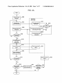
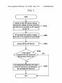
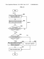
Compute optimal
connection
configuration
v
N $150
check connection
Check connection ,._, $151
signal
signal
I
~ 5160
Store connection
status information
_
$170
Modify connection #13183
for all device
No
status
completed?
A
N 8181
configuration
.
optimal?
Yes
s1 82
Display connection
configuration
error information
reattempt
N°
Patent Application Publication Feb. 10, 2005 Sheet 8 0f 17
US 2005/0034160 A1
FIG. 4B
G) C‘)
@ G)
@ (E)
regeiver
(3) i
l-_---_ - - - _ __ ----‘
><
CF) @ @
631.1%
An external input of (3) TV was erroneously connected to (.0 DVD Combo.
It Is recommended that a component terminal of @
TV is connected to 6) DVD Combo.
Patent Application Publication Feb. 10, 2005 Sheet 9 0f 17
US 2005/0034160 A1
FIG. 5
(
start
D
1
power on the AV device whose
connection status to know and: the
AV device to transmit an AV signal w 3510
to ‘the TV
1
AV termini?! into which a signai w 5520
from the TV IS inputted IS searched
1
power off the AV device
"\.¢ $53.0
S540
.
is the sigma!
yes
ingutted into the searched
- V terminal of the TV?
it is determined’that the AV cable
of the AV device is connected to f 5550
the selected‘ AV tea-mine!
C
l
end
Patent Application Publication Feb. 10, 2005 Sheet 10 0f 17
US 2005/0034160 A1
FIG. 6A
Input port
\
no
RxD
hardware logic
for RS-232C
UART
/\/
Microprocessor
or CPU
Buffer
‘
(3Q)
‘
Output port
GPIO
W—]
U 0|‘
TXD
RxD
enableldisable
control
(clefaull: enable)
/
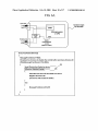
DescoveryAddressDeviceO
{
MessageFromDevice=TRUE;
Broadcast to all device to disable the control buffer and clear all device ID
While(MessageFromDevice==FALSE)do
{
(A)
Send WhoAreYou Packet to device N
if(Receive WholAm Packet) /\/(B)
{
Generate new device ID and send it to device
Register the device ID
(The device will enable the buffer)
}
else
{
MessageFromDevice=FALSE
)
Patent Application Publication Feb. 10, 2005 Sheet 11 0f 17
US 2005/0034160 A1
FIG. 6B
UpdateDeviceStatusQ
{
for(id=id_start id < id__'end; id++)
{
Ilquery device status and store the return value
DevicéStatus = QueryDevice'Status(id);
l/IF there is no return value, DeviceStatus is NULL
lf(DeviceStatus == NULL)
{
remove the device ID
else
{
llupdate the device status information
Device[id].$tatus = DeviceStatus;
Patent Application Publication Feb. 10, 2005 Sheet 12 0f 17
US 2005/0034160 A1
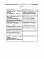
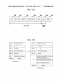
FIG. 7
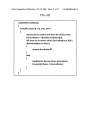
When image transmission possible
When image transfer is impossible
Whether back panel image exists or not : yes
Whether back panel image exists or not : no
Back panel image
The number of the component input/output tenninal
Back panel image inlormation (type, color, width, height)
Type Of component input/output terminal (DW/DVDl-")
The number of the component input/output terminal
The l'wmbel 0f the exmmal input/output terminal
Type of component input/output lamina‘ (DTWDVDI...)
Type of the external input/output terminal (MonitorNCRl---)
Central coordinates on image in each of component input/output
The number of S-video input/output terminal
terminal (YIPblPr, UR)
The number of the external input/output terminal
Type of S-video input/output terminal (DVDNCRI..)
Type of the external inputloutput terminal (monitorNCRl---)
The number of antenna input/output terminal
‘Central coordigaitjaon Image in each of external input/output
Type of antenna inpuuoutpm terminal (coaxiawn)
The number of S-video inputloutput terminal
The number of digital audio input/output terminal
Type of S-video input/output terminal (DVDNCRI"')
Type of digital audio inputloutput terminal (DVDlSATI---)
Central coordinates on image m each of S-wdeo inputloutput
terminal
External Input/output terminal number of audio connected to 8
video input/output terminal
The number of antenna input/output terminal
The number of external ampli?er output terminal
Type of external ampli?er output terminal (FLlFRl-r')
‘
Type of antenna inputloutput terminal (coaxiall---)
Central coordinates on image in each of antenna input/output
terminal
The number of digital audio input/output terminal
Type of digital audio inpu'tloutput terminal (DVDlSATl---)
Central coordinates on image In each of digital audio mputioutput
terminal
The number of external ampli?er output terminal
Type of external ampli?er output terminal (FUFRIW)
Central coordinates on image in each of external ampli?er output
lerminaKL/R)
The number of subwooler output terminal
Central coordinates on image in each of subwoofer output terminal
The number of subwooter output terminal
Patent Application Publication Feb. 10, 2005 Sheet 13 0f 17
US 2005/0034160 A1
FIG. 8
N=1
H5801
inquire the number of N-th
ranked input terminal
i
Search for AV device having H5802
N-th ranked output terminals
N=N+1
S803
Is AV device
having N-th ranked output
terminais found?
Yes
Are devices more
than N-th ranked output
terminals found?
Hsaos
Map output terminal of AV device
to input terminai of master
device in sequence
l
Store connection status
,-..1
H3806
_
Input user’s 5919mm"
8807
<-----—---
Patent Application Publication Feb. 10, 2005 Sheet 14 0f 17
US 2005/0034160 A1
FIG. 9A
l
Start
I
V
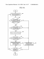
Power off all searched AV
N
$901
devices except for TV
Is a connection
jack coupled to component
input terminal of the W
mapped to AV devic = .
ls signal input
to relevant component input
terminal of TV?
8904
Power on relevant AV device
$905
ls signal input
to relevant component input
Yes
terminal of TV?
Determine that the relevant
connection status is
norma'and storevthe
resu“
Is the check
completed for all
connections?
D
A] 8906
_ '
I
etermine re evant
N 3908
connection status as
error and store the result
Patent Application Publication Feb. 10, 2005 Sheet 15 0f 17
US 2005/0034160 A1
FIG. 9B
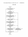
S911
Power on all searched AV
devices except for TV
S912
connectin '
jack coupled to
component output terminals
of TV matched to A
device?
Mute on so that signal is not output
5913
from relevant component output
terminals of TV
Mute off so that signal is outputted
from relevant component out put
terminals of TV
5915
8916
ether signal is inpu ~_
to component input terminal
of search AV
device
No
, S917
Determine that relevant
V
connection status is normal
Determine relevant
connection status to be an
and store the result
error and 5 ore the result
S919
i re all connections
checked?
3918
Patent Application Publication Feb. 10, 2005 Sheet 16 0f 17
US 2005/0034160 A1
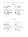
FIG. 10A
1010
Header
1020
Source ID
1030
Destination ID
1040
Message Type
1050
Body Length
1060
Body
message header
i070
Chccitsum
massage
FIG. 10B
Header
OxABBAldiscriminator)
Src. lD
TV
Dest. ID
AV device
Header
OxABBA (discriminator)
Src. ID
M59 Type
panel information inquiry
Body Len.
Body size
Body
back panel information request
Dest. ID
,
AV device
TV
M59, Type
panel information response
Body Len.
Body size
Existence or non-existence of back panel image
Back panel image (in existence)
checksu'"
check 5w“
B d
0
Back panel image information (in existence)
Number of component input and output terminals
.
y
Request packet
Number of subwoofer output terminals
Checksum
check sum
Response packet
Patent Application Publication Feb. 10, 2005 Sheet 17 0f 17
US 2005/0034160 A1
FIG. 10C
Header
OxABBA (discriminator)
Header
oxAaaAidiscriminator)
Src. ID
TV
Src. ID
AV device
Desi. ID
AV device
Dost. ID
TV
Msg. Type
Signal inputinqulry
Body Len.
Body size
Body
____> Msg. Type
First component input terminal
Checksum
check sum
Signal input response
Body Len.
Body size
Body
On or Off
Checksum
check sum
Request packet
Response packet
FIG. 10D
Header
Src.
ID
Dest. ID
OxABBA (discriminator)
Header
TV
Src.
AV device
Desi. ID
Msg. Type
device control command
Body Len.
AV device
TV
Msg. Type
device control response
Body size
Body Len.
Body size
Body
power on or 0“
Body
success or failure
checksum
check sum
Checksum
check sum
Request packet
_______v>
10
OXABBA (discriminator)
Response pac K et
Feb. 10, 2005
US 2005/0034160 A1
METHOD AND SYSTEM FOR CONTROLLING
PERIPHERAL DEVICES CONNECTED TO A
VIDEO DEVICE
BACKGROUND OF THE INVENTION
[0001] This application claims the priority of Korean
Patent Application No. 10-2003-0055230 ?led on Aug. 9,
2003, in the Korean Intellectual Property Of?ce, the disclo
sure of Which is incorporated herein in its entirety by
reference.
[0002]
1. Field of Invention
[0003]
The present invention relates to a method for
guiding connection betWeen a video device (e.g., TV) and
external peripheral devices (e.g., AV devices such as an AV
to con?rm Whether the connection is normally established
before actually using the AV devices, considerable time and
effort is needed.
[0008]
Thus, there is a need for a method for informing a
user of the optimal connection con?guration by referring to
information about respective AV devices upon connecting
the respective AV devices to a TV.
SUMMARY OF THE INVENTION
[0009] Illustrative, non-limiting embodiments of the
present invention overcome the above disadvantages, and
other disadvantages not described above.
[0010] A method consistent With the present invention
provides a process for automatically receiving device infor
receiver, a digital versatile disc (DVD) player, a DVD
mation from external peripheral devices connected to a
recorder, a DVD Combo, a video cassette recorder (VCR),
a cable set-top box, a satellite set-top box and a ground Wave
video device and computing optimal connection con?gura
set-top box) through a screen so that a user can easily make
the connection betWeen the devices. More particularly, the
present invention relates to a method and apparatus for
effectively performing optimal connection con?guration by
recogniZing the connection status betWeen a video device
and external peripheral devices.
[0004] 2. Description of the Related Art
[0005]
According to conventional methods, a TV and AV
tion betWeen the video device and the external peripheral
devices.
[0011] Further, a method consistent With the present
invention provides a process for suggesting optimal connec
tion status When the current connection status is not optimal
by checking the current connection status betWeen a video
device and external peripheral devices.
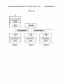
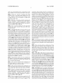
[0012]
Still further, a method consistent With the present
invention provides guidance by Which a user can folloW
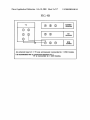
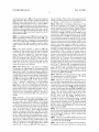
devices are connected through AV cables to transmit and
con?guration for AV cable connection While vieWing the
receive video signals and audio signals, as shown in FIG. 1.
screen of a video device.
For such connection, a user refers to the user’s manuals of
the respective AV devices to make connection therebetWeen
through the AV cables. When the connection through the AV
cables is completed, con?rmation is made as to Whether the
functions of the AV devices are normally performed after the
TV and the relevant AV devices are poWered on. At this time,
a method for con?rming these functions involves sWitching
to an external input to Which a relevant AV device is
connected and then to check Whether a picture is normally
displayed on the screen of the TV. If the picture is not
displayed normally, the user should solve this problem by
referring again to the user’s manual of the relevant AV
device or by receiving the assistance of other people.
[0006]
For such a method, it is not easy for a general user
having no knoWledge of AV devices to correctly connect the
AV devices Without trial and error because the user must
determine the methods for connecting the AV devices by
himself/herself. Further, as the number of methods for
making connection betWeen a video device and peripheral
devices increases With the development of neW technolo
gies, it is becoming more dif?cult for a user to recogniZe
Which connection method among a number of possible
connection methods Will establish optimal connection con
?guration. For example, if an AV device is a DVD player, a
component terminal for video is connected to a TV to obtain
the highest clear image quality, and a digital audio output for
audio is connected to the TV to obtain the best audio.
HoWever, a general user may not knoW such a fact and
attempt to connect a normal AV output to the TV to vieW
video.
[0007] As described above, a general user having no
knoWledge on the functionality and properties of AV devices
may undergo this trial and error process several times to
connect the AV devices to a TV. Further, since it is dif?cult
[0013] According to an aspect of the present invention,
there is provided a method for intelligently con?guring
connection betWeen a video device and peripheral devices,
comprising a ?rst step of sensing peripheral devices con
nected to a netWork and giving a unique identi?er to each of
the connected peripheral devices; a second step of request
ing back panel information to the peripheral devices and
receiving back panel information from the peripheral
devices; a third step of computing optimal connection con
?guration betWeen the video device and the peripheral
device based on the back panel information; and a fourth
step of checking Whether the video device and the peripheral
devices are connected to each other in conformity With the
optimal connection con?guration.
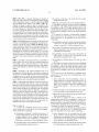
[0014] According to another aspect of the present inven
tion, there is provided a system comprising a video device
and at least one peripheral device. The video device com
prises a packet generating unit for searching for the periph
eral device, inquiring back panel information, and producing
a data packet conforming to a protocol for checking con
nection status; a memory for storing connection status
information indicating the connection status With the periph
eral device; a graphic generating unit for graphically pro
ducing connection status betWeen the devices using the back
panel information received from the peripheral device; and
a control unit for sensing the connected peripheral device
using the data packet, requesting the back panel information
of the peripheral device to compute optimal connection
con?guration, and determining Whether the current connec
tion status is optimal based on the computed results. The
peripheral device comprises a transceiver unit for transmit
ting and receiving data to and from the video device through
netWork connection; a packet generating unit for producing
a response packet to the request packet of the video device;
Feb. 10, 2005
US 2005/0034160 A1
a memory for storing the back panel information of the
peripheral device; and a control unit for checking the back
panel information and checking a connection signal With the
video device.
BRIEF DESCRIPTION OF THE DRAWINGS
checking Whether connection con?guration is normal in
steps S150 to S170 of FIG. 4A;
[0032]
FIG. 10A is a diagram shoWing an entire structure
of a transmission/reception packet;
[0033]
FIG. 10B is a diagram illustrating an example of
?eld names and contents of a packet used in requesting back
[0015] The above and other objects and features of the
present invention Will become apparent from the folloWing
description of exemplary embodiments of the present inven
panel information in step S110 of FIG. 4A and responding
back panel information in step S113 of FIG. 4A;
tion given in conjunction With the accompanying draWings,
[0034]
in Which:
?eld names and contents of a transmission/reception packet
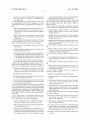
[0016] FIG. 1 is a diagram illustrating a con?guration of
an existing system;
[0017]
FIG. 2 is a block diagram shoWing an apparatus
according to the present invention in a state Where the
apparatus is divided into a video device side and a peripheral
device side for the purpose of illustration;
FIG. 10C is a diagram illustrating an example of
used in requesting to check a connection signal in step S150
and responding check results in step S151 of FIG. 4A; and
[0035]
FIG. 10D is a diagram illustrating an example of
?eld names and contents of a transmission/reception packet
used When an AV device is poWered on and off in FIGS. 9A
and 9B.
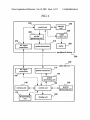
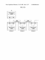
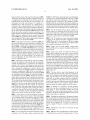
[0018] FIG. 3A is a diagram illustrating a connection
con?guration of a system according to the present invention;
DETAILED DESCRIPTION OF THE
INVENTION
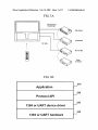
[0019] FIG. 3B is a diagram illustrating a layer structure
of softWare and hardWare for implementing IEEE 1394 and
invention Will be described in detail With reference to the
RS-232C schemes;
[0020]
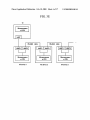
FIG. 3C is a block diagram illustrating a TV and
[0036] Hereinafter, exemplary embodiments of the present
accompanying draWings.
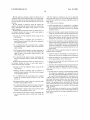
[0037]
FIG. 2 is a block diagram shoWing an apparatus
FIG. 3D is a block diagram illustrating a TV and
according to the present invention in a state Where the
apparatus is divided into a video device side and a peripheral
device side for the purpose of illustration. According to the
present invention, a video device 100 such as TV includes a
AV devices connected to one another in a daisy-chain
transceiver unit 110 for transmitting and receiving data to
AV devices connected to one another through 1394 connec
tion lines using a hub;
[0021]
scheme that does not use a hub, using IEEE 1394;
[0022]
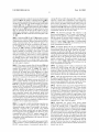
FIG. 3E is a block diagram illustrating a TV and
AV devices connected to one another in a daisy-chain
scheme, using RS-232C (Recommended Standard 232 Revi
sion C) cables;
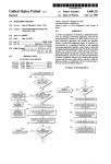
[0023] FIG. 4A is a ?oWchart generally shoWing a method
for con?guring device connection according to the present
invention;
[0024]
FIG. 4B is a diagram illustrating an example of a
con?guration error screen;
and from a peripheral device such as an AV device over a
netWork connection using a RS-232C cable or the like; a
packet generating unit 120 for searching for a peripheral
device 200, inquiring back panel information of the periph
eral device, and creating a data packet conforming to a
protocol for checking connection status; a memory 140 for
storing connection status information indicating the connec
tion status With the peripheral device 200; a graphics gen
erating unit 150 for producing a graphic indicating the
connection status betWeen the devices using the back panel
information received from the peripheral device 200; a
control unit 130 for sensing the connected peripheral device
[0025] FIG. 5 is a How chart illustrating a method to knoW
to Which AV device each of AV terminals connect;
200 using the data packet, requesting back panel information
of the peripheral device, computing optimal connection
[0026]
con?guration, and determining Whether the current connec
tion status is optimal; and an ID generating unit 170 for
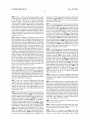
FIG. 6A is a diagram explaining a scheme for
automatically giving IDs to external AV devices;
[0027]
FIG. 6B is a diagram checking Whether external
AV devices on a netWork are deleted in the scheme for
automatically giving IDs to the external AV devices;
[0028]
FIG. 7 is a table for explaining an example of back
panel information;
[0029]
FIG. 8 is a ?oWchart speci?cally explaining the
process of mapping video input terminals of a TV to video
output terminals of an AV device in computing optimal
connection con?guration in step S140 of FIG. 4A;
[0030] FIG. 9A is a ?oWchart speci?cally explaining the
process of checking a component video input signal in
checking Whether connection con?guration is normal in
steps S150 to S170 of FIG. 4A;
[0031] FIG. 9B is a ?oWchart speci?cally explaining the
process of checking a component video input signal in
producing and giving a unique device ID for each peripheral
device.
[0038] An AV signal transceiver 180 transmits analog
signals for video or sound to the slave device, and receives
the signals from the slave device through an AV cable
according to a control command generated in the packet
generating unit 120. For example, the signals inputted from
the AV signal transceiver 180 comprises a YPbPr video
signal inputted from a component terminal, an S-video
signal inputted from an S-video terminal, a sound signal
inputted from a digital audio terminal, or a sound signal
inputted from an analog audio terminal Whereas the signals
outputted from the AV signal transceiver 180 comprise a
video signal outputted from a TV or a sound signal outputted
from a TV.
[0039] MeanWhile, the peripheral device 200 includes a
transceiver unit 210 for transmitting and receiving data to


![ft.757gx ]i hf all mode computer aided transceiver](http://vs1.manualzilla.com/store/data/005735092_1-f8362b9c1e3279439f07a335507c2c8e-150x150.png)