1
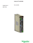
Lexium Controller User's manual DeviceNet Retain for future use 30072 - 452 - 84 LMC20A 1309 Contents Important Information _________________________________________________________________________________________ 4 Documentary structure ________________________________________________________________________________________ 5 Introduction _________________________________________________________________________________________________ 6 Presentation _____________________________________________________________________________________________ 6 Notation ________________________________________________________________________________________________ 6 Quick start__________________________________________________________________________________________________ 7 Hardware setup _____________________________________________________________________________________________ Receipt _________________________________________________________________________________________________ Hardware description ______________________________________________________________________________________ Coding the switches _______________________________________________________________________________________ 8 8 8 9 Wiring to the network ________________________________________________________________________________________ 10 Cable routing practices ____________________________________________________________________________________ 10 Wiring the DeviceNet connector _____________________________________________________________________________ 10 Configuring ________________________________________________________________________________________________ 12 Configuring _____________________________________________________________________________________________ 12 Configuring the communication scanner ______________________________________________________________________ 12 Configuring by a network tool __________________________________________________________________________________ Network tool ____________________________________________________________________________________________ Going online with RSNetWorx ______________________________________________________________________________ Creating an EDS file ______________________________________________________________________________________ Configuring the DeviceNet scanner __________________________________________________________________________ Editing objects of the Lexium Controller _______________________________________________________________________ 14 14 14 14 15 19 Creating a PLC program______________________________________________________________________________________ 21 Using I/O messaging _____________________________________________________________________________________ 21 Using explicit messaging __________________________________________________________________________________ 21 Diagnostics by the LMC HMI __________________________________________________________________________________ Checking the node address and the data rate __________________________________________________________________ Signalling LED __________________________________________________________________________________________ Monitoring the communication scanner _______________________________________________________________________ Troubleshooting the communication interruption ________________________________________________________________ 22 22 23 24 24 DeviceNet objects___________________________________________________________________________________________ Supported classes _______________________________________________________________________________________ Identity object ___________________________________________________________________________________________ Message router object ____________________________________________________________________________________ DeviceNet object_________________________________________________________________________________________ Assembly object _________________________________________________________________________________________ Connection object ________________________________________________________________________________________ Acknowledge handler object________________________________________________________________________________ Application objects _______________________________________________________________________________________ DeviceNet interface object _________________________________________________________________________________ 25 25 26 29 30 31 33 37 38 40 While every precaution has been taken in the preparation of this document, Schneider Electric assumes no liability for any omissions or errors it may contain, nor for any damages resulting from the application or use of the information herein. The products described in this document may be changed or modified at any time, either from a technical point of view or in the way they are operated. Their description can in no way be considered contractual. 3 Important Information NOTICE Read these instructions carefully, and look at the equipment to become familiar with the device before trying to install, operate, or maintain it. The following special messages may appear throughout this documentation or on the equipment to warn of potential hazards or to call attention to information that clarifies or simplifies a procedure. The addition of this symbol to a Danger or Warning safety label indicates that an electrical hazard exists, which will result in personnal injury if the instruction are not followed. This is the safety alert symbol. It is used to alert you to potential personal injury hazards. Obey all safety messages that follow this symbol to avoid possible injury or death. DANGER DANGER indicates an imminently hazardous situation, which, if not avoided, will result in death, serious injury, or equipment damage. WARNING Warning indicates a potentially hazardous situation, which, if not avoided, can result in death, serious injury, or equipment damage. CAUTION CAUTION indicates a potentially hazardous situation, which, if not avoided, can result in injury or equipment damage. PLEASE NOTE Electrical equipment should be installed, operated, serviced, and maintained only by qualified personnel. No responsibility is assumed by Schneider Electric for any consequences arising out of the use of this material. BLMT00014 © 2008 Schneider Electric. All rights reserved. WARNING LOSS OF CONTROL - The designer of any control scheme must consider the potential failure modes of control paths and, for certain critical control functions, must provide a means to achieve a safe state during and after a path failure. Examples of critical control functions are emergency stop and overtravel stop. - Separate or redundant control paths must be provided for critical control functions. - System control paths may include communication links. Consideration must be given to the implications of unanticipated transmission delays or failures of the link.1 - Each implementation of a Lexium Motion Controller must be individually and thoroughly tested for proper operation before being placed into service. Failure to follow these instructions can result in death, serious injury, or equipment damage. 1. For additional information refer to NEMA ICS 1.1 (latest edition), "Safety Guidelines for the Application, Installation, and Maintenance of Solid State Control" 4 Documentary structure This manual is part of a series describing the Lexium Motion Controller (LMC). The following manuals may be downloaded at www.us.telemecanique.com Installation manual This manual describes: • controller installation, • controller connection. Optional graphic terminal user manual This manual describes: • graphic terminal installation, • graphic terminal connection, • controller programming by graphic terminal. EasyMotion - Programming manual (Not available in the USA) Delivered pre-installed in Lexium Controller motion controllers, the application model associated with EasyMotion mode is an ergonomic tool enabling: • fast configuration of axes, • use of Manual/Automatic mode, • creation of positioning tasks, • editing of cam profiles, • backup and restore of machine parameters, • diagnostics of the motion controller and its different axes. This Programming manual also comprises the table of the parameters accessible by the communications protocols. MotionPro - Programming manual The MotionPro programming manual is included in software online help. This online help describes: • software ergonomics, • IEC 1131 programming, • function libraries (standard functions, motion control functions, application functions), • Lexium controller configuration screens. Modbus, Ethernet, Profibus DP and DeviceNet manuals These manuals describe: • connection to bus or network, • diagnostics, • software installation, • protocol communication services 5 Introduction Presentation The DeviceNet communication bus is used to connect a Lexium Controller to a DeviceNet network. The communication interface has an open-style 5-pin connector for connection to the network. Data exchanges give access to all Lexium Controller: • Command, • Monitoring, • Diagnostics. DeviceNet cables and connecting accessories must be ordered separately. Notation Formats Hexadecimal values are written as follows: 16# Binary values are written as follows: 2# Vocabulary Depending on DeviceNet document and tools, equivalent wordings are used. The table below shows vocabulary used in the present document and other corresponding definitions. In this document Other Node address DeviceNet address, MAC ID Data rate Baud rate kbit/s kBPS, kbps, k Setpoint Reference, target Path Object Address Comments Class, instance, attribute The reader should avoid mixing two terms: - DeviceNet scanner, which is the master device on the DeviceNet network. - Communication scanner, which is a function inside the Lexium Controller. Abbreviations Req. = Required Opt. = Optional 6 Quick start This section is provided to help experienced users quickly start using the DeviceNet interface. If you are unsure how to complete a step, refer to the referenced chapter. Step Refer to 1 Review the safety precautions for the Lexium Controller. Installation manual 2 Verify that the Lexium Controller is properly installed. Installation manual 3 Install the Lexium Controller Installation manual 4 Verify that the Lexium Controller is not powered. Hardware setup 5 Commission the DeviceNet interface. Hardware setup Set an unique node address and the appropriate data rate using the switches on the interface. If desired, you can disable the switches and use parameter settings instead. 6 Connect the Lexium Controller to the DeviceNet network. Verify that the Lexium Controller is not powered. Then, connect the interface to the network using a DeviceNet cable. Wiring to the network 7 Apply power to the Lexium Controller. The status indicator should be green.If it flashes red, there is a problem (refer to Signaling LED). Diagnostics by the LMC HMI 8 Check with Motion Pro / CoDeSys by using the Browser the information coming from the DeviceNet module. 9 Apply power to the DeviceNet master and other devices on the network. DeviceNet master manuals Verify that the master and network are installed and functioning in accordance with DeviceNet (DeviceNet cable system planning standards, and then apply power to them. and Installation manual ...) 10 Configure the scanner to communicate with the Lexium Controller. Configuring the DeviceNet scanner Use a network tool such as RSNetWorx for DeviceNet to configure the scanner on the network. Make sure to: Set up the scan list, Map the Lexium Controller data to the scan list, Save your DeviceNet configuration to the scanner in a file. 11 Create a PLC program Control the Lexium Controller using I/O (assemblies). Monitor or configure the Lexium Controller using Explicit Messages. Creating a PLC program DeviceNet master manuals 7 Hardware setup Receipt • Check that the Lexium Controller reference printed on the label is the same as that on the delivery note corresponding to the purchase order. • Remove the Lexium Controller from its packaging and check that it has not been damaged in transit. CAUTION DAMAGED CONTROLLER Do not install or operate any Lexium Controller that appears damaged. Failure to follow these instructions can result in injury or equipment damage. Hardware description DeviceNet signaling unit DeviceNet Connector Address configuration switches 8 Hardware setup Coding the switches Switches description high = OFF = 0 low = ON = 1 Node address Data rate Overriding the switches When switches 7 and 8 are set in position low (ON = 1), the data rate and the node address of the Lexium Controller must be set by a network tool (refer to Configuring by a network tool). Default values are 125 kbit/s and node address 63. Coding the data rate All devices connected to the DeviceNet network must communicate at the same data rate: 125, 250, or 500 kbit/s. The table below shows the switch settings that configure the DeviceNet data rate on the Lexium Controller. Switch 7 0 0 1 1 Switch 8 0 1 0 1 Data rate 125 kbit/s 250 kbit/s 500 kbit/s The DeviceNet data rate and the node address of the Lexium Controller must be set by a network tool. Any change to the switch setting takes effect at the next power-up. Coding the node address All devices connected to the DeviceNet network must have an unique address, ranging from 0 to 63 (decimal). If the data rate switches (7 and 8) are both set to 1 (on), the switches 1 to 6 are ignored and the node address must be set by a network tool (default value = 63). The table below lists the switch setting for each valid node address. Any change to the switch setting takes effect at the next power-up. Node address 00 01 02 03 04 05 06 07 08 09 10 11 12 13 14 15 Switches 12 3456 00 0000 00 0001 00 0010 00 0011 00 0100 00 0101 00 0110 00 0111 00 1000 00 1001 00 1010 00 1011 00 1100 00 1101 00 1110 00 1111 Node address 16 17 18 19 20 21 22 23 24 25 26 27 28 29 30 31 Switches 12 3456 01 0000 01 0001 01 0010 01 0011 01 0100 01 0101 01 0110 01 0111 01 1000 01 1001 01 1010 01 1011 01 1100 01 1101 01 1110 01 1111 Node address 32 33 34 35 36 37 38 39 40 41 42 43 44 45 46 47 Switches 12 3456 10 0000 10 0001 10 0010 10 0011 10 0100 10 0101 10 0110 10 0111 10 1000 10 1001 10 1010 10 1011 10 1100 10 1101 10 1110 10 1111 Node address 48 49 50 51 52 53 54 55 56 57 58 59 60 61 62 63 Switches 12 3456 11 0000 11 0001 11 0010 11 0011 11 0100 11 0101 11 0110 11 0111 11 1000 11 1001 11 1010 11 1011 11 1100 11 1101 11 1110 11 1111 Examples Data rate = 250 kbit/s (switches 7 and 8 = 2#01) Node address = 25 (switches 1 to 6 = 2#01 1001) Data rate = 500 kbit/s (switches 7 and 8 = 2#10) Node address = 52 (switches 1 to 6 = 2#11 0100) 9 Wiring to the network Cable routing practices When wiring Lexium Controller to a DeviceNet network, follow all wiring practices required by national and local electrical codes. Also observe the following guidelines: • Avoid areas of high temperature, moisture, vibration, or other mechanical stress. • Secure the cable where necessary to prevent its weight and the weight of other cables from pulling or twisting the cable. • Use cable ducts, raceways, or other structures to protect the cable. Use these structures for signal wiring paths. They must not contain power wiring. • Avoid sources of electrical interference that can induce noise into the cable. Use the maximum practicable separation from such sources. When planning cable routing within a building, follow these guidelines: • Maintain a minimum separation of 1 m (3.28 ft) from sources of electromagnetic interference, such as: - air conditioners and large blowers, - elevators and escalators, - radios and televisions, - intercom and security systems, - fluorescent, incandescent, and neon lighting fixtures. • Maintain a minimum separation of 3 m (9.84 ft) from stronger electromagnetic interference generating equipment, such as: - line and motor power wiring, - transformers, - generators, - alternators. When wiring in electrical equipment rooms or large electrical equipment line-ups, observe the following guidelines for cable segregation and separation of circuits: • Use metallic conduit for Lexium Controller wiring. Do not run control network and power wiring in the same conduit. • Separate non-metallic conduits or cable trays used to carry power wiring from metallic conduit carrying low-level control network wiring by at least 300 mm (11.8 in). • Separate metallic conduits carrying power wiring or low-level control network wiring by at least 80 mm (3.15 in). • Cross the metallic conduits and non-metallic conduits at right angles whenever power and control network wiring cross. • Attenuate conducted emissions from the Lexium Controller to the line in some installations to prevent interference with telecommunication, radio, and sensitive electronic equipment. Such instances may require attenuating filters. Consult the Lexium Controller catalog for selection and application of these filters. Wiring the DeviceNet connector The figures and the table below show the pin-outs of the Lexium Controller connectors. The removable DeviceNet female connector attaches to the network cable. 1 2 3 4 5 1 DeviceNet male connector 2 3 4 5 Removable DeviceNet female connector Pin Name Color 1 GND Black 2 CAN_L Blue 3 SHIELD Bare 4 CAN_H White 5 V+ Red Line termination: If the Lexium Controller is the first or the last device on the DeviceNet network, a line terminator (121 Ω resistor) must be wired on the removable DeviceNet female connector, between pins 2 and 4 (CAN_L and CAN_H). 10 Wiring to the network The ODVA standards (Release 2.0) specify 7 types of cables for use in DeviceNet networks: • Thick cable • Thin cable • Flat cable • Cable I • Cable II • Cable IV • Cable V The table below lists main specifications of cables. For more information, refer to the ODVA specifications. Type of cable Data conductor pair size Power conductor pair size Data impedance Thick cable 18 AWG 15 AWG 120 Ω +/- 10 % (at 1 MHz) Thin cable 24 AWG 22 AWG 120 Ω +/- 10 % (at 1 MHz) Flat cable 16 AWG 16 AWG 120 Ω +/- 10 % (at 500 kHz) Cable I 24 AWG 22 AWG 120 Ω +/- 10 % (at 1 MHz) Cable II 18 AWG 15 AWG 120 Ω +/- 10 % (at 1 MHz) Cable IV 18 AWG 16 AWG 120 Ω +/- 10 % (at 500 kHz) Cable V 18 AWG 16 AWG 120 Ω +/- 10 % (at 500 kHz) The maximum permissible length of the network cable depends on the data rate and the type of cable. Type of cable Data rate 125 kbit/s 250 kbit/s 500 kbit/s Thick cable 500 m (1640 ft) 250 m (820 ft) 100 m (328 ft) Thin cable 100 m (328 ft) 100 m (328 ft) 100 m (328 ft) Flat cable 420 m (1378 ft) 200 m (656 ft) 75 m (246 ft) Cable I 100 m (328 ft) 100 m (328 ft) 100 m (328 ft) Cable II 500 m (1640 ft) 250 m (820 ft) 100 m (328 ft) Cable IV - - - Cable V 420 m (1378 ft) 200 m (656 ft) 75 m (246 ft) For maximum length of the drops refer to table, whatever type of cable: Data rate Cumulative drop Maximum drop 125 kbit/s 156 m (516 ft) 6 m (20 ft) 250 kbit/s 78 m (256 ft) 6 m (20 ft) 500 kbit/s 39 m (128 ft) 6 m (20 ft) 11 Configuring Configuring Principle Numerous configurations are possible. For more information, refer to the Programming manual. The following configurations are some of the possibilities available. DeviceNet communication Network interface is used to connect a LMC20A1309 Controller on a DeviceNet Network. Data can be exchanged to manage all of the Lexium Controller functionality. The DeviceNet interface is a DeviceNet node slave. • %MW access • Monitoring, • diagnostic Control with communication scanner To monitor and control the LMC20A1309 Controller, it is relevant to exchange cyclic data with the default assemblies (100, 101). These assembly's can be used to exchange data between an external DeviceNet Master PLC and the LMC20A1309 Available configurations The assemblies available are: • 100: Communication scanner output. • 101: Communication scanner input. The examples below are only possible if you use the communication scanner. Configuring the communication scanner Please refer to this section if using the assemblies 100 or 101. The variables exchanged by the output assembly 100 and input assembly 101 are discribed in MotionPro / CoDeSys software. The 4 output variables of the assembly 100 are assigned by means of the 4 parameters. The 4 input variables of the assembly 101 are assigned by means of the 4 parameters These 8 assignment parameters are described in the tables below: Parameter name Output assembly 100 Default assignment [DNET-I0] [DNET-I1] [DNET-I2] [DNET-I3] %IW16 Word %IW17 Word %IW18 Word %IW19 Word Parameter name Input assembly 101 Default assignment [DNET-O0] [DNET-O1] [DNET-O2] [DNET-O3] %QW16 Word %QW17 Word %QW18 Word %QW19 Word 12 Configuring It is possible to read the DeviceNet configuration under MotionPro / CoDeSys. The tree of the parameters are given. 13 Configuring by a network tool Network tool RSNetWorx for DeviceNet is a Rockwell® software application that can be used to set up DeviceNet networks and configure connected devices. RSNetWorx for DeviceNet (version 2.22.18) is used for examples in this manual. Different versions of software may differ in appearance and procedures. Proper EDS (electronic data sheet) file (LMC20A_E.eds) and icone (LMC20.ico) for LMC20A1309 controller are distributed on the CD-ROM delivered with each LMC20A1309. They are also available on the Internet : www.us.telemecanique.com Going online with RSNetWorx You can view the devices on a DeviceNet network by going online. A device may appear as an unrecognised device if RSNetWorx does not have an EDS file for it. 1 After setting up a Lexium Controller in RSLinx, start RSNetWorx for DeviceNet. 2 Select Network > Online. If the Browse for Network dialog box appears, RSLinx has multiple Lexium Controller configured. Select your DeviceNet network, and click OK. A prompt appears. 3 Click OK to go online. The devices on the network appear in the Configuration View. You can select Graph, Spreadsheet, or Master/Slave views. The figure below shows an example network in a Graph view. Creating an EDS file If the adapter and Lexium Controller appear as an unrecognized device, create an EDS file for it. 1 Right-click the "Unrecognized Device" icon, and select Register Device in the menu. The EDS Wizard appears. 2 Click Next to display the next step. 3 Select Upload EDS, and then click Next. 4 Type a description (if desired), and then click Next. 5 Under Polled, select Enabled, type 4 in the Input Size and Output Size boxes, and then click Next. RSNetWorx will upload the EDS file from the deviceNet interface. 6 Click Next to display the icon options for the node. We recommend that you use the icon for your product. You can change icons by clicking Change icon. Proper EDS file (LMC20A_E.eds) and icone (LMC20.ico) for LMC20A1309 controller are distributed on the CD-ROM delivered with each LMC20A1309. They are also available on the Internet : www.us.telemecanique.com 7 Click Next to view a summary, and then click Next again to accept it. 8 Click Finish to finish the EDS creation. A new icon represents the Lexium Controller in the Configuration View. 14 Configuring by a network tool Configuring the DeviceNet scanner Setting up the scan list For the scanner to communicate with a Lexium Controller, the scanner must be configured and the Lexium Controllers node number must be added to its scan list. 1 Go online with RSNetWorx for DeviceNet. The devices on the network are displayed in the configuration view. 2 Right-click the DeviceNet scanner (node 00) and select Properties. The Scanner Module dialog box appears. Important: If your scanner is an unrecognized device, you must create an EDS file for it and then configure the scanner. Configure the scanner using the General and Module tabs. If you need more information, click Help or refer to your scanner documentation. 3 Click the Scanlist tab. A message box prompts you to upload. 4 Click Upload. Data is uploaded from the scanner, and then the Scanlist page appears. 5 Select the Automap on Add box (a check mark will appear). 6 Under Available Devices, select the Lexium Controller, and then click > (Right Arrow) to add it to the scanlist. 15 Configuring by a network tool 7 Under Scanlist, select the Lexium Controller, and then click Edit I/O Parameters. The Edit I/O Parameters dialog box appears. 8 Select the type(s) of data exchange (Polled, Change of State, and /or Cyclic). In our example, we selected Polled. The type supported by the DeviceNet interface for Lexium Controller are: Input (Rx, produced) Output (Tx, consummed) Polled COS Cyclic Strobe • • • • No No No No 9 Type the number of bytes that are required for your I/O in the Rx Size and Tx Size boxes. The size will depend on the assembly you have selected for your application: Assembly attribute Assembly name Rx size 101 Communication scanner input 8 bytes Assembly attribute Assembly name Tx size 100 Communication scanner output 8 bytes 10 Set the scan rate. (Click Help for more information.) Data Exchange Rate to set Polled Polled Rate Change of State Heartbeat Rate Cyclic Send Rate 11 Click OK. If you changed any settings, a Scanner Applet asks if it is OK to unmap the I/O. Click Yes to continue. The Edit I/O Parameters dialog box closes and then the Scanner Module dialog box reappears. You will map the I/O in the next section in this chapter. 16 Configuring by a network tool Mapping the Lexium Controller data in the scanner Data from I/O messages must be mapped in the scanner. This mapping determines where a PLC program can find data that is passed over the network. You must map both the Input I/O and the Output I/O. Mapping the inputs: In the Scanner Module dialog box, click the Input tab. (If necessary, right-click the scanner in the configuration view to display this dialog box.) If you selected the Automap on Add box in the Scanlist page, RSNetWorx has already mapped the I/O. If it is not mapped, click Automap to map it. If you need to change the mapping, click Advanced and change the settings. Click Help for assistance. 17 Configuring by a network tool Mapping the outputs: In the Scanner Module dialog box, click the Output tab. To display this dialog box, right-click the scanner in the configuration view. If you selected the Automap on Add box in the Scanlist page, RSNetWorx has already mapped the I/O. If it is not mapped, click Automap to map it. If you need to change the mapping, click Advanced and change the settings. Click Help for assistance. Saving the Configuration After configuring a scanner, you must download the configuration to the scanner. You should also save it to a file on your computer. 1 In the Scanner Module dialog box, click Apply to save the configuration to the scanner. A Scanner Configuration Applet appears and asks if it is OK to download the changes. 2 Click Yes to download the changes. The changes are downloaded and then the Scanner Module dialog box reappears. 3 Click OK to close the Scanner Module dialog box. 4 Select File > Save. If this is the first time that you saved the project, the Save As dialog box appears. Navigate to a folder, type a file name, and click Save to save the configuration to a file. 18 Configuring by a network tool Editing objects of the Lexium Controller Using the Class Instance Editor DeviceNet objects of the Lexium Controller can be edited with the Class Instance Editor of RSNetWorx. This editor provides direct access to the device using native DeviceNet object addressing. Using this editor requires a detailed understanding of the capabilities and limitations of the device being configured, as well as the possible impacts that these changes may have on the operation of your system. You assume full responsibility for all consequences related to the use of this editor. 1 Go online with RSNetWorx for DeviceNet. The devices on the network are displayed in the configuration view. 19 Configuring by a network tool 2 Right-click on the icon for the Lexium Controller and select Class Instance Editor. The Lexium Controller dialog box appears. 3 In the Object Address field, type the path of the parameter in the boxes Class, Instance, Attribute. 4 In the Service Code field, select the action in the Description box. 5 In the boxes Transmit data size, Data sent to the device, Values in decimal type the description of the data that you want to send to the Lexium Controller. 6 Click Execute to exchange the data with the Lexium Controller. Click Help for assistance. Configuring node address and data rate If the data rate switches (7 and 8) are set to 1, configure node address and data rate by the Class Instance Editor. Node address Base Class Instance Attribute Hexadecimal 16# 03 16#01 16#01 Decimal 3 1 1 Class Instance Attribute Data rate Base Hexadecimal 16# 03 16#01 16#02 Decimal 3 1 2 20 Creating a PLC program Using I/O messaging I/O messaging is used to transfer real time data between the PLC and the Lexium Controller : • Commands, • Setpoints, • Settings, • States, • Measurements, • ... To obtain the best response time in the application choose the adequate exchange method: • Change of State (COS), • Cyclic, • or Polled. The exchange method is downloaded in the Lexium Controller by the DeviceNet scanner and must be configured by network tool (refer to Configuring the DeviceNet scanner). Using explicit messaging I/O messaging is used to transfer data that does not require continuous updates between the PLC and the Lexium Controller : • Configuration, • Settings, • Fault parameters, • Log parameters; • ... If the PLC program configures the Lexium Controller using explicit messaging. The new value of the parameters are not stored in EEPROM and they will be lost at next power off. To store the values of parameters (whole configuration) in EEPROM, it is necessary to set to 1 the bit 1 of Extended control word (CMI), refer to the Communication parameters manual. 21 Diagnostics by the LMC HMI Checking the node address and the data rate It is possible to read the Baudrate and the node address with MotionPro / CoDeSys software by using PLC Browser command. The command is "Optioncardinf" (for option card information). The list of informations given by this command is: Soft Version: 1.0ie1 Hard Version: 1.0 BaudRate: 52 - 1250000 Bauds 60 - 250000 68 - 500000 1 0 to 63 Address: 22 Diagnostics by the LMC HMI Signaling LED The DeviceNet features one combined Module/Network Status LED (MNS), which is visible through the Lexium Controller cover: MNS LED status indication LED state Lexium Controller state Indication Off Device is not on line • The device is not powered. • The device has not completed the duplicate node address test yet. Flashing green Device is operational and on line, but not connected OR Device is on line but needs commissioning The device is on line and operating in a normal condition, but network connections are not established. • The device has passed the duplicate node address test and is on line, but has not established connections to other nodes. • The device is not allocated to a master. • Configuration is missing, incomplete, or incorrect. Rapid flashing green Device is operational, online, and connected The device is operating in a normal condition. It is allocated to a master. Flashing red Major fault and/or connection time-out • The device has experienced a major recoverable fault. • One or more I/O connections timed out. Rapid flashing red Critical fault or critical link failure • The interface has a major unrecoverable fault and may need replacing. • The device has detected an error that has rendered it incapable of communicating on the network (duplicate node address or bus turned off). Flashing green / red Communication fault The device has detected a Network Access error and is in the Communication Faulted state. The device has subsequently received and accepted an Identify Communication Faulted Request—Long Protocol message. Note: After power on, the MNS LED quickly glows green then red and finally turns off. 23 Diagnostics by the LMC HMI Monitoring the communication scanner Use Motion Pro / CoDeSys to see the value of the Data value exchanged on DeviceNet. Troubleshooting the communication interruption DeviceNet faults are indicated by the LED on the Lexium Controller. The [Network fault] parameter can be used to obtain more detailed information about the origin of the last fault. It can be accessed under Motion Pro / CoDeSys by using the Browser and by monitoring the Status Error or Status Network available in the sheet PLC configuration. Information is available by the command "Optioncardinf" in the PLC browser. Status Error: Status Network: 0 - No Error 1 - User Default 2 - Duplicate MacId 3 - CAN Fifo RX 4 - CAN Fifo TX 5 - CAN Overrun 6 - Sending 7 - CAN Bus Off 8 - Time out on explicit or periodic connection 9 - Acknowledgment on periodic connection 0 - No Connection 1 - Device self testing 2 - StandBy 3 - Operational 4 - Major Recoverable Fault 5 - Major Unrecoverable Fault End of DeviceNet Configuration Info This parameter is available in the DeviceNet Interface object (16#64 = 100), attribute 4. Value 24 Description of the values of the [Network fault] parameter 0 No fault 1 Fault triggered by the user This type of fault can be triggered by the parameter "ForceFault/trip" of the Control Supervisor object (16#28 = 41), attribute 17. 2 Duplicate node address (MAC ID) 3 CAN FIFO RX error 4 CAN FIFO TX error 5 CAN overrun 6 CAN transmit error 7 CAN bus off 8 Control time out. COS, cyclic, polling or explicit messaging restart the timer. The time out can be configured in the parameter "Expected_packet_rate" of the Connection object (5), attribute 9. 9 Acknowledge error, for COS or cyclic only. The error can be configured in the parameters "Acknowledge Timer" and "Retry Limit" of the Acknowledge Handler object, attributes 1 and 2. These events may be caused by loose or broken cables or by noise. These events may be caused by loose or broken cables or by noise. DeviceNet objects Supported classes Object class Class ID Need for ODVA conformance No. of instances Effect on behavior Interface Hex. Dec. Identity 16#01 1 Required 1 Supports the reset service Message router Message router 16#02 2 Optional 1 DeviceNet 16#03 3 Required 1 Configures node attributes Message router Assembly 16#04 4 Required 13 Defines I/O data format Message router, assembly, or parameter object DeviceNet connection 16#05 5 Required 3 Logical ports into or out of the device I/O connection or message router Acknowledge handler 16#2B 43 Optional 1 Application 16#64 16#6A 100106 Optional DeviceNet interface 16#80 128 Optional Explicit message connection I/O connection or message router Vendor specific object Message router or parameter object 1 25 DeviceNet objects Identity object The Identity object provides identification and status information about the Lexium Controller. Class code Hexadecimal Decimal 16#01 1 Class attributes Attribute ID Access Name Need Data type Value Details 1 Get Revision Opt. UINT 1 — 2 Get Max Instances Opt. UINT 1 1 defined instance Instance attributes Attribute ID Access Name Need Data type Value Details 1 Get Vendor ID Req. UINT 243 Schneider Automation, Inc [243] 2 Get Device type Req. UINT 16#00 Generic Device 3 Get Product code Req. UINT 1 or 5 9: (LMC) 4 Get Revision Req. Struct of: USINT USINT — Product revision of the Lexium Controller (1) 5 Get Status Req. WORD — See definition in the table below 6 Get Serial number Req. UDINT — Serial number of the Lexium Controller 7 Get Product name Req. Struct of: USINT STRING — 24 (product name length) “Lexium Controller” 8 Get Opt. State (see Figure on page 28) USINT — 0: Non existent 1: Device self-testing 2: Standby 3: Operational 4: Major recoverable fault 5: Major unrecoverable fault 10 Get/Set Heartbeat interval (2) USINT 0–255 Interval in seconds between two heartbeat messages. 0: No message. Opt. (1) Mapped in a word: MSB minor revision (second USINT), LSB major revision (first USINT). Example: Decimal 517 = 16#0205 means revision V5.2. (2) The heartbeat message broadcasts the current state of the device. 26 DeviceNet objects Attribute 5–status Bit Definition 0 Owned by master (predefined master/slave connection) 2 Configured (not used) 8 Minor recoverable fault (not used) 9 Minor unrecoverable fault (not used) 10 Major recoverable fault 11 Major unrecoverable fault Others Reserved 0 (reset to 0) Class service Service code Service name Need Description 16#0E Get_Attribute_Single Req. Read an attribute Service code Service name Need Description 16#0E Get_Attribute_Single Req. Read an attribute 16#10 Set_Attribute_Single (1) Write an attribute 16#05 Reset Req. Reset DeviceNet module Instance service (1) Required if the heartbeat interval must be defined. 27 DeviceNet objects State diagram for the Identity object Nonexistent Key Name of the state Power loss (from any state) Off Power Applied NMS LED STATUS Device self testing Identity object reset service (from any state except Major unrecoverable fault) Failed tests Flashing red/green Passed tests Standby Fault corrected Flashing green Activated Desactivated Minor fault Operational Solid green Major recoverable fault Major recoverable fault Flashing red 28 Major unrecoverable fault Major unrecoverable fault Solid red DeviceNet objects Message router object The Message router object is the element through which all the "Explicit messages" objects pass in order to be directed towards the objects they are truly destined to. Class code Hexadecimal Decimal 16#02 2 Class attributes Attribute ID Access Name Need Data type Value Details 1 Get Revision Opt. UINT 1 - 2 Get Max instances Opt. UNT 1 1 Defined instance Instance attributes Attribute ID Access Name Need Data type Value Details 1 Get Object list: Number classes Opt. Struct of: UINT UINT [ ] 20 (codes) List of supported objects; the first UINT is the number of supported classes; the remaining UINTs are the codes of these classes. 2 Get Number available Opt. UINT 1 Maximum number of simultaneous connections 3 Get Number active Opt. UINT 1 Number of active connections 4 Get Active connections Opt. UINT [ ] 1 List of active connections (referred to with their respective Connection instance ID) Class service Service code Service name Need Description 16#0E Get_Attribute_Single Req. Read an attribute Service code Service name Need Description 16#0E Get_Attribute_Single Req. Read an attribute Instance service 29 DeviceNet objects DeviceNet object The DeviceNet object provides the status and configuration of a DeviceNet node. Class code Hexadecimal Decimal 16#03 3 Class attributes Attribute ID Access Name Need Data type Value Details 1 Get Revision Opt. UINT 2 — 2 Get Max Instances Opt. UINT 1 1 Defined instance Instance attributes Attribute ID Access Name Need Data type Value Details 1 Get/Set (1) Node address Req. USINT 0–63 See below 2 Get/Set (1) Data rate Opt. USINT 0–2 0 = 125 kbit/s; 1 = 250 kbit/s; 2 = 500 kbit/s See below 3 Get/Set BOI (BusOff interrupt) Opt. BOOL — Upon BusOff event: 0: CAN component remains in BusOff 1: Component is reset and communication resumes 4 Get/Set BusOff counter Opt. USINT 0–255 Number of occurrences of BusOff state. Set access is used to reset this counter. 5 Get Allocation information Opt. BYTE USINT — 0–63 Allocation choice Master address (255 not allocated) (1) Use Set access only if data rate switches (7 and 8) are both set to 1 (ON). Class service Service code Service name Need Description 16#0E Get_Attribute_Single Req. Read an attribute Instance service Service code Service name Need Description 16#0E Get_Attribute_Single Opt. Read an attribute 16#10 Set_Attribute_Single Opt. Write an attribute 16#4B Allocate Master/Slave Connection Set Opt. Allocation connection master/slave 16#4C Release Master/Slave Connection Set Opt. Release connection master/slave 30 DeviceNet objects Assembly object Class code Hexadecimal Decimal 16#04 4 Class attribute Attribute ID Access Name Need Data type Value Details 1 Get Revision Opt. UINT 2 — 2 Get Max instance Opt. UINT 101 2 defined instances Instances supported Instance Name Data size 100 Communication scanner output 8 bytes 101 Communication scanner input 8 bytes Instance attributes Attribute ID Access Name Need 3 Get/Set (1) Data Req. Data type Value Details (1) Set access is restricted to output instance only (instance 100). Class service Service code Service name Need Description 16#0E Get_Attribute_Single Req. Read an attribute Instance service Service code Service name Need Description 16#0E Get_Attribute_Single Req. Read an attribute 16#10 Set_Attribute_Single Opt. Write an attribute 31 DeviceNet objects Output assembly 100 Bytes 0 and 1 1st Scanner out parameter [DNET_O0] Bytes 2 and 3 2nd Scanner out parameter [DNET_O1] Bytes 4 and 5 3rd Scanner out parameter [DNET_O2] Bytes 6 and 7 4th Scanner out parameter [DNET_O3] Input assembly 101 Bytes 0 and 1 1st Scanner in parameter [DNET_I0] Bytes 2 and 3 2nd Scanner in parameter [DNET_I1] Bytes 4 and 5 3rd Scanner in parameter [DNET_I2] Bytes 6 and 7 4th Scanner in parameter [DNET_I3] 32 DeviceNet objects Connection object Class code Hexadecimal Decimal 16#05 5 Class attributes Attribute ID Access Name Need Data type Value Details 1 Get Revision Opt. UINT 1 — 2 Get Max instances Opt. UINT 4 3 defined instances (1) (1) Only instances 1 (explicit message), 2 (polled I/O message), and 4 (change of state/cyclic message) are supported. Instance 3 (bit strobe) is not supported. Attributes of instance 1—Explicit message instance Attribute ID Access Name Need Data type Value Details 1 Get State Req. USINT — 0 : Non-existent 3 : Established 5 : Deferred Delete 2 Get Instance_type Req. USINT 0 Explicit Message 3 Get TransportClass_trigger Req. BYTE 16#83 Class 3 server 4 Get Produced_connection_id Req. UINT 10xxxxxx011 xxxxxx = Node address 5 Get Consumed_connection_id Req. UINT 10xxxxxx100 xxxxxx = Node address 6 Get Initial_comm_characteristics Req. BYTE 16#21 Explicit messaging via Group 2 7 Get Produced_connection_size Req. UINT 36 Produced data maximum size (in bytes) 8 Get Consumed_connection_size Req. UINT 36 Consumed data maximum size (in bytes) 9 Get/Set Expected_packet_rate Req. UINT 2500 2.5 sec. (TimeOut) 12 Get/Set Watchdog_timeout_action Req. USINT 1 or 3 1 : Auto-Delete 3 : Deferred Delete (Default) 13 Get Produced connection path length Req. UINT 0 Length of attribute 14 data 14 Get Produced connection path Req. Array of UINT Null Empty 15 Get Consumed connection path length Req. UINT 0 Length of attribute 16 data 16 Get Consumed connection path Req. Array of UINT Null Empty Refer to DeviceNet specification for more information. 33 DeviceNet objects Attributes of instance 2—Polled I/O message instance Attribute ID Access Name Need Data type Value Details 1 Get State Req. USINT — 0: Non-existent 1: Configuring 3: Established 4: TimeOut 2 Get Instance_type Req. USINT 1 I/O Message 3 Get TransportClass_trigger Req. BYTE 16# 83 Class 3 server 4 Get Produced_connection_id Req. UINT 01111xxxxxx xxxxxx = Node address 5 Get Consumed_connection_id Req. UINT 10xxxxxx101 xxxxxx = Node address 6 Get Initial_comm_characteristics Req. BYTE 16# 01 Group 1 / Group 2 7 Get Produced_connection_size Req. UINT 4, 6, or 8 Size of data produced 8 Get Consumed_connection_size Req. UINT 4, 6, or 8 Size of data consumed 9 Get/Set Expected_packet_rate Req. UINT — Exchange frequency (ms) 12 Get/Set Watchdog_timeout_action Req. USINT 0, 1, or 2 (2) 0: Transition to TimeOut 1: Auto-Delete 2: Auto-Reset 13 Get Produced_connection_path length Req. UINT 8 Default: 8 bytes 14 Get/Set Produced_connection_path Req. Array of UINT 16# 20 04 24 65 30 03 Input assembly (Default : Instance 101, 16# 20 04 24 65 30 03) 15 Get Consumed_connection_path length Req. UINT 8 Default: 8 bytes 16 Get/Set Consumed_connection_path Req. Array of UINT 16# 20 04 24 64 30 03 Output assembly (Default : Instance 100, 16# 20 04 24 64 30 03) 17 Get/Set Production_inhibit_time Cond. UINT 0 Minimum time between 2 data productions. Undefined 34 DeviceNet objects Attributes of instance 4—Change of state/cyclic message instance Attribute ID Access Name Need Data type Value Details 1 Get State Req. USINT — 0: Non-existent 1: Configuring 3: Established 4: TimeOut 2 Get Instance_type Req. USINT 1 I/O Message 3 Get TransportClass_trigger Req. BYTE 16# X2 Class 2 Client Cos:16# 12 - Cyclic:16# 02 4 Get Produced_connection_id Req. UINT 01101xxxxxx xxxxxx = Node address 5 Get Consumed_connection_id Req. UINT 10xxxxxx101 xxxxxx = Node address 6 Get Initial_comm_characteristics Req. BYTE 16# 01 Group 1 / Group 2 7 Get Produced_connection_size Req. UINT 4, 6, or 8 Size of data produced 8 Get Consumed_connection_size Req. UINT 0 Size of data consumed 9 Get/Set Expected_packet_rate Req. UINT — Exchange frequency (ms) 12 Get/Set Watchdog_timeout_action Req. USINT 0, 1, or 2 (2) 0: Transition to TimeOut 1: Auto-Delete 2: Auto-Reset 13 Get Produced_connection_path_length Req. UINT 8 Default: 8 bytes 14 Get/Set Produced_connection_path Req. Array of UINT 16# 20 04 24 65 30 03 Input assembly (Default : Instance 101, 16# 20 04 24 65 30 03) 15 Get Consumed_connection_path_length Req. UINT 8 Default: 8 bytes 16 Get/Set Consumed_connection_path Req. Array of UINT 16# 20 2B 24 01 30 03 Output assembly: The first and only one instance of the Acknowledge handler object (Class ID 16#2B) 17 Get/Set Production_inhibit_time Cond. UINT 0 Minimum time between 2 data productions. Undefined 35 DeviceNet objects Class service Service code Service name Need Description 16#08 Create Opt. Instantiation of a connection 16#0E Get_Attribute_Single Req. Read an attribute Instance service Service code Service name Need Description 16#0E Get_Attribute_Single Req. Read an attribute 16#10 Set_Attribute_Single Opt. Write an attribute 16#05 Reset Opt. Reset Inactivity/Watchdog timer 36 DeviceNet objects Acknowledge handler object The acknowledge handler object directs the acknowledgment of messages received. Class code Hexadecimal Decimal 16#2B 43 Class attributes Attribute ID Access Name Need Data type Value Details 1 Get Revision Opt. UINT 1 — 2 Get Max instance Opt. UINT 1 — Instance attributes Attribute ID Access Name Need Data type Value Details 1 Get/Set Acknowledge timer Req. UINT 16 Default: 16 ms 2 Get/Set Retry limit Req. USINT 1 — 3 Get/Set COS producing connection instance Req. UINT 4 Assembly Class service Service code Service name Need Description 16#0E Get_Attribute_Single Req. Read an attribute Service code Service name Need Description 16#0E Get_Attribute_Single Req. Read an attribute 16#10 Set_Attribute_Single Req. Write an attribute Instance service 37 DeviceNet objects Application objects Class code Hexadecimal Decimal 16#64 to 6A 100 to 106 Lexium Controller parameters path The Lexium Controller parameters are grouped in classes. Each application class has 100 instances from 1 to 100. Each instance groups 100 Motion Pro / CoDeSys object (%MW). Each attribute in an instance relates to a Motion Pro / CoDeSys object. The first Motion Pro / CoDeSys object registered in the first application class (class code: 16#64 is %MW0). Examples: Address Path Hexadecimal 3 000 16# 64 / 1F / 01 10 000 16# 65 / 01 / 01 100 / 31 / 01 10 16# 64 / 01 / 0B 100 / 01 / 11 Class = Instance = Attribut = Path decimal 101 / 1 / 1 [Adr / 10 000] + 100 [(Adr MOD 10000) / 100] + 1 [Adr MOD 100] + 1 If an address is Adr = XY AB CD in decimal the value for Class/Instance/Attribut is: Class = Instance = Attribut = XY + 100 AB + 1 CD + 1 To perform the Motion Pro / CoDeSys Address with the DeviceNet address given by Class/Instance/Attribut is: Adr = (Class - 100) x 10 000 + (Instance - 1) x 100 + Attribut - 1 When a read access to the class 6A h is done for the address between 65 536 and 69 999 the returned value is 8 000 h. A write access is not take into account for the same range of Address. 38 DeviceNet objects Class attributes Attribute ID Access Name Need Data type Value 1 Get Revision Opt. UINT 1 2 Get Max instance Opt. UINT 100 6 Get Max ID number of class attribute Opt. UINT 7 7 Get Max ID number of instance attribute Opt. UINT 100 Instance attributes Attribute ID Access Name Data type Value 1 Get/Set First parameter of the class UINT / USINT Value returned by the Lexium Controller ... ... ... ... ... X Get/Set Last parameter of the class UINT / USINT Value returned by the Lexium Controller Note: Depending on the parameter, write access may be prohibited. Refer to the Communication parameters manual for more information. Class service Service code Service name Need Description 16#0E Get_Attribute_Single Req. Read an attribute Service code Service name Need Description 16#0E Get_Attribute_Single Req. Read an attribute 116#0 Set_Attribute_Single Opt. Write an attribute Instances service 39 DeviceNet objects DeviceNet interface object Class code Hexadecimal Decimal 16#80 128 Class attributes Attribute ID Access Name Need Data type Value 1 Get Revision Opt. UINT 1 2 Get Max instance Opt. UINT 1 6 Get Max ID number of class attribute Opt. UINT 7 7 Get Max ID number of instance attribute Opt. UINT 2 Instances attributes Attribue ID Access Name Data type Details 1 Get [Network fault] USINT 0 : no fault 1 : user forced fault 2 : duplicate Node Address 3 : CAN FIFO RX Error 4 : CAN FIFO TX Error 5 : CAN OverRun 6 : CAN send Error 7 : CAN Bus Off 8 : Control Time Out 9 : Acknowledge Error 2 Get Software revision of the DeviceNet interface UINT Ex : 16# 1109 = V1.1ie09 40 DeviceNet objects Class service Service code Service name Need Description 16#0E Get_Attribute_Single Req. Read an attribute Service code Service name Need Description 16#0E Get_Attribute_Single Req. Read an attribute 16#10 Set_Attribute_Single Opt. Write an attribute Instance services 41 30072 - 452 - 84 09.2008