1
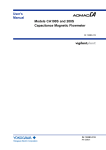
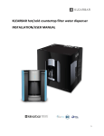
MODEL B1750
POSITIVE DISPLACEMENT
FLOW METER
INSTALLATION & INSTRUCTION
MANUAL
8635 Washington Avenue
Racine, Wisconsin 53406
Sales Toll-Free: 800.235.1638
Phone: 262.639.6770 Fax: 262.417.1155
www.blancett.com
2
TABLE OF CONTENTS
General Description ................................................................ 4
Installation ............................................................................... 4
Flow Meter Guidelines for Paint Operations ....................... 8
Typical Automated Cleaning Cycle ..................................... 10
Calibrations ........................................................................... 12
0DLQWDLQFH*XLGH
Troubleshooting Guide ......................................................... Statement of Warranty ......................................................... 3
GENERAL DESCRIPTION
The Blancett B1750 positive displacement gear flow meters are
similar in design to the gear pump. The principle of operation is
reversed; instead of the gears driving the medium, the medium
drives the gears. A non-intrusive magnetic pick-up or hall-effect
sensor detects the movement of the gear and as each gear tooth
passes the sensor a square wave pulse is produced and a discrete
volume of liquid is measured. The resulting pulse train is
proportional to the actual flow rate and provides a highly accurate
representation of the fluid flow. All meters are designed with
highly wear resistant moving parts to provide exceptionally long
service life.
Filtration:
Depends upon model.
Fluid Compatibility:
The materials of construction include stainless steel or high
strength aluminum housings, stainless steel gears and either
tungsten carbide or stainless steel bearings (depending upon the
model). The fluids should be compatible with these materials.
INSTALLATION INSTRUCTIONS
The preferred flow direction is etched or marked by an arrow on
the meter as this is the flow direction in which the meter was
calibrated. However, the flow meters have bi-directional flow
capabilities. Damage will not occur from reverse flow, but the
meter will count reverse flow as forward flow. To prevent this
possibility, an in-line check valve may be a consideration.
The preferred orientation is to mount the meter vertically;
although horizontal mounting is acceptable if conditions deter
vertical orientation. There is no need for straight run piping
upstream or downstream of the flow meter.
4
Figure 1
Install the meter upstream from control valves and fluid
regulators if possible. See Figure 1. Back pressure from control
valving is beneficial for stable running.
Eliminate all dirt, debris and metal shavings from the piping as
the liquid must be free from any particles larger than allowed by
the manufacturer’s specifications. Any recommended filtration
should be installed before operation as potential plugging most
often occurs at startup.
If possible, install a by-pass around the meter and flush existing
piping with the appropriate solvent before first use. See Figure 1.
Review the pick-up instructional guide prior to installation.
Locate the pick-up and wiring away from A/C motors, actuators,
heaters, relays, etc. Use only shielded cable and do not take
power from the same circuits as other devices. Ensure clean
power supplies which utilize a true earth ground. Intrinsic safety
barriers must be installed if the circuit is intended to be
intrinsically safe.
The pick-up sensor should only be installed hand tight - do not
use wrenches or channel locks. Over tightening may cause a
dimple to protrude into the meter chamber beneath the pick-up
and interfere with the free gear rotation.
5
Maintenance Guides are provided with the meter and are also
available from the factory. These should always be reviewed by
personnel prior to attempting any maintenance work. The
overwhelming majority of downtime and repairs are the result of
breakages due to improper maintenance actions, lack of training
or rough handling.
Never run the meter dry or spin with air only. Gear flow meters
are precision engineered flow devices and should always be
maintained in a clean, lubricated condition with the internals wet
at all times. Air and water should not be allowed in contact with
the internal parts except in short (1-2 second) cycles as part of an
automated flush.
Do not use water for flow testing. The viscosity of water is too
low to produce accurate results unless the flow rate is elevated,
and the internals would then have to be dried and lubricated to
avoid corrosion or scaling. Using a fluid with a viscosity of
approximately 30 cSt, such as mineral oil or thinned glycerin, is
recommended if calibration of the system is necessary. The
preferred calibration fluid would be the actual fluid to be metered.
Do not ramp-up flow to a full flow condition instantaneously.
Gear flow meters are rugged, yet precise instruments which will
respond almost instantaneously to changes in fluid flow. Normal
pulsating flows will not damage the meter and will merely cause
the output to be unsteady. However, if flow is repeatedly cycled
from zero to full flow instantaneously, fluid shock forces may be
significant and may produce premature damage or wear over
time. To avoid damage to the system, ramp-up to maximum flow
over a few seconds rather than instantaneously and do not inject
high flow speeds into an empty meter.
Filtration is recommended to prevent contaminants from entering
the meter. Should the meter become plugged, a reduced flow
may still be observed from the outlet as fluid pressure will
squeeze fluid through the meter. Visual flow does not necessarily
mean that the meter’s gears are turning. If plugging is caused by
6
contaminants, then filtering should be installed. If plugging is
repeatedly caused by particle build up, then review the cleaning
and maintenance procedures in the following section. Because of
the vast differences in fluid types and in-plant procedures, there
may be some trial and error involved in determining the ideal
flushing or cleaning regimen.
A calibration factor (K-factor) is established at the factory on a
preferred calibrating fluid. This number is usually accurate for a
wide variety of fluids and should not usually be changed. It is
provided with the meter either on a Calibration Data Sheet or on a
tag attached to the meter. Should it be lost, a copy can be
obtained from the factory. A calibration verification procedure is
detailed later in this document.
Storage - when the flow meter is idle or stored for any extended
period of time, the internals should be thoroughly cleaned with
the appropriate solvent, lubricated with a light oil and the ports
capped or plugged to prevent drying.
7
FLOW METER GUIDELINES
FOR PAINT OPERATIONS
Before installing, operating or attempting maintenance on a flow
meter read the appropriate Maintenance Guide. As with any
precision engineered device, the equipment should always be
operated and maintained in accordance with the manufacturer’s
instructions.
Flow meters are designed to flow liquids which assist in cooling
and lubrication. Meters should always be closed to air except
when air is part of an automated purge cycle. In this case the air
segments are typically under 1-2 seconds and are interspersed
with lubrication solvent to achieve a scrubbing effect. The air
segments are short enough that the meter doesn’t dry out. See
Figure 2. Do not dry paint lines using only pressurized air as
this will lead to premature wear.
Figure 2
At the end of a shift or overnight, it is strongly recommended that
cleaning solvent or DI water with appropriate cutting agent be left
in the meter, under pressure, to soak. This helps keep unflushed
residual paint from drying and helps subsequent start-ups.
Opening a meter after a flush cycle will help determine if the
meter is being cleaned thoroughly by the purge.
Regular cleaning cycles with solvent or DI water may be
necessary to effect color changes or to prevent some coatings
from depositing on critical internal parts. Designing and
8
maintaining a flush procedure which keeps the meter internals
clean and wet is critical to optimum performance and minimum
maintenance. Cleaning cycles will vary due to differences in
coatings, equipment and cleaning fluids used. Some testing may
be prudent to determine the most efficient method. Cleaning
cycles using DI water only may require more flushing than those
using additives due to the superior cutting ability of solvents. If
bells or small orifices restrict adequate purge through the meter,
an auxiliary dump valve of ¼" or Ǫ" may be installed after the
meter to maximize through flow.
Full flow meter breakdown instructions are included in the
Maintenance Guide. When a meter is removed from the line
during maintenance, paint should not be allowed to dry inside.
The internals should be immediately cleaned, lubricated and the
fluid ports capped. Clean the carbide surfaces at the point where
the gear rotates on the shaft. Paint build-up here may occur as a
thin smear and be difficult to see, but will cause friction and
accelerate additional paint build-up later when the gears are
reinstalled. Spin the gears by hand to verify free and easy
rotation of gear on shaft and apply a suitable lubrication fluid
before closing the meter. After tightening the bolts, a short squirt
of shop air will briefly spin the gears which should be easily
audible. When reinstalling the sensor, turn it in lightly only to a
hand tight torque. Do not use a wrench on the pick-up as over
tightening may cause damage.
In the event of plugging, the meter will pass a reduced volume of
fluid with an increased back pressure and no frequency output.
Care during installation is important as this is the most likely time
that contaminants such as tape or metal shavings can enter the
meter. Filters should be installed in the line to prevent oversize
particles from entering the flow meter.
In the event the meter needs to be returned to the factory for
further evaluation, flush the meter in place and cap the ports.
9
TYPICAL AUTOMATED CLEANING CYCLE
At the beginning of the cleaning cycle, clean with DI water for a
significant period of time before introducing any air at all into the
system. For example, the first thing the meter should see after
push out is a relatively long blast of solvent or DI water for at
least 3 seconds or more depending on the coating. In the middle
of the cleaning cycle, short (0.5 sec) air blasts will maximize the
scrubbing effect. At the end of the cleaning cycle, finish with
solvent or DI water instead of air. The intention is to put enough
purge fluid into the system at this time to have the meter soaking
in clean flush fluid at the end of the cycle. When there are gaps
in the line or when line stops occur after a color change,
following this procedure will keep the meter from potentially
freezing up. In general, the meter should never see air for more
than a few seconds and should never be run dry. Note: If new
paint and purge fluid mixing is a problem, the fill cycle can start
with a short 1 second shot of air to separate the purge fluid and
the paint.
During line shutdowns, such as overnight and over weekends,
meters should be flushed and left filled with solvent, under
pressure, to allow any residue that may have built up to soak and
dissolve.
Filtration is recommended to prevent contaminants from entering
the meter. Should the meter become plugged, a reduced flow will
still be observed from the nozzle or outlet as fluid pressure will
squeeze fluid through the meter. Should this occur, review the
cleaning and maintenance procedures in the following sections.
10
FLOW METER GUIDELINES
FOR PAINT OPERATIONS
DO: Leave flushing solvent in the lines overnight or during
extended off-times. This keeps internals wet, preventing
residual paint from drying and helping start ups.
DO: Follow the Maintenance Guide instructions when
opening and cleaning a meter. During cleaning,
separate the gears from the shafts. On carbide
bearings, clean inside the center of the gear bearing
and on the outer surface of the shafts at the point
where the gear rotates on the shaft. Apply a suitable
lubricating fluid before closing the meter. After
tightening the bolts, a short squirt of shop air will
briefly spin the gears which should be easily audible.
DO: Install and maintain filters. The recommended filter
should be installed to eliminate potential plugging.
Should plugging occur, the meter will still pass fluid
but with no signal output.
DO:
Check electrical compatibility between the meter’s
output signal and the input of the PLC. If signals are
not being detected at start up, first check wiring and
electrical compatibility.
DO: Verify reliable grounding of electrical parts, as per
installation guidelines, and a dedicated power supply
is recommended. Voltage spikes on shared power
lines, negligent grounding and sloppy wiring will
likely produce erratic readings and chronic
maintenance. The control valve will provide back
pressure which is beneficial to stable flow control.
DO: Install the meter immediately upstream of the
regulator or control valve. The control valve provides
back pressure which stabilizes the flow.
DON’T: Allow air into the flow meter. Always keep the meter
internally wet.
11
DON’T: Dry paint lines using pressurized air. Flow meters are
designed to flow liquids. Meters should be closed to
air except when air is part of an automated purge
cycle. Do not dry lines after purging.
DON’T: Allow materials to dry inside the meter. When a
meter is removed from the line during maintenance,
the internals should be immediately cleaned,
lubricated and the fluid ports capped.
DON’T: Over tighten the pick-up sensor beyond hand tight.
When installing the pick-up sensor, turn it in lightly to
a hand tight torque. Do not use a wrench on the pickup as over tightening may cause a dimple of metal
under the sensor nose to protrude into the gear cavity
and interfere with the gear’s rotation.
DON’T: Use water or solvent for calibration or test purposes.
Water or solvent may not turn the gears at low flow
and may leave the impression that the meter is not
functioning. A calibration factor (K-factor) is issued
with the flow meter which is valid for most fluids
except water or equivalent viscosities.
CALIBRATIONS
Each flow meter is calibrated and given a K-factor using a
standard calibrating fluid at the factory. This number is accurate
for all fluids, with most viscosities, except the most water-like.
There should be no need to change this except for the very lowest
viscosities close to 1.0 cP.
If flow readings are too high: If the display shows significantly
more than the volume actually dispensed or shows flow when
there is definitely no flow, this most likely indicates an electrical
noise problem. In such cases, turn off nearby motors, heaters or
relays, check cable shielding and establish a clean ground
independent of other electrical devices before repeating accuracy
12
tests. If the problem continues, it may be necessary to relocate
the offending device.
If flow readings are too low: If the display shows significantly
less than the volume actually dispensed, then most likely the
meter has a high slippage factor and the fluid is by-passing the
gears and the K-factor may require adjustment.
If it is necessary to adjust the existing K-factor: Trigger at least
500ml of your sample fluid, in a steady stream, at approximately
the desired flow rate, into a graduated beaker. Compare the
volume in the beaker to the volume on the display. Do not time
the operation merely measure the volume dispensed. Repeat the
sample 3 times and take an average. If the result is outside an
acceptable margin, adjust the K-factor by the percentage
difference between the average beaker sample and the average
displayed total. If the error is not corrected, clean the meter
thoroughly and repeat the procedure. Do not use water for this
test.
If it is necessary to re-calculate a new K-factor: You will first
need a data collecting instrument to count pulses produced by the
meter. A Blancett display may be used in totalizer mode
provided the KFT is set to count each pulse (KFT = 10000).
Trigger at least 500ml of your sample fluid, in a steady stream, at
approximately the desired flow rate, into a graduated beaker.
Divide the number of pulses by the volume dispensed and the
result is your new K-factor in the units of your sample. In the
example above the K-factor units would be impulses/ml.
13
TROUBLESHOOTING GUIDE
TROUBLE
POSSIBLE CAUSE
x Viscosity of fluid is
Meter indicates
<30cSt
lower than actual
SOLUTION
x Decrease the K-factor by
percent error
x Excessive pressure
differential across meter
causing gears to bind
x Reduce flow rate, reduce
fluid viscosity
x Debris in measuring
chamber
x Clean meter, change or
add filter
x Upper housing has dimple x Replace upper housing
from over tightening
sensor
Meter indicates
higher than
actual
Indicator shows
flow when there is
no flow
14
x Air in lines
x Add air eliminator
x Electro-magnetic
interference
x Ground flow meter and
all electronics
x Reverse fluid flow
x Add check valve
x Fluid oscillates
x Check pump, add check
valve, increase back
pressure
x Electro-magnetic
interference
x Ground flow meter and
all electronics. Use
shielded cable and
relocate away from
electrical noise.
15
16
17
18
19
20
TROUBLESHOOTING GUIDE (cont’d)
TROUBLE
POSSIBLE CAUSE
No flow indication x No fluid flow
SOLUTION
x Check pump
x Debris in measuring
chamber or gears
x Clean meter, change or
add filter
x Sensor not installed
properly
x Check sensor is installed
to hand tight. Review
sensor guide.
x Faulty wiring
x Check sensor
connections and readout
connection
x Faulty sensor
x Replace sensor
x Upper housing has dimple x Replace upper housing
from over tightening
sensor
Erratic system
indication
x Ground loop in shielding
x Ground shield one place
only. Re-route cables
from electrical noise.
x Pulsating fluid flow
x Add pulse dampener
NOTES
STATEMENT OF WARRANTY
Blancett Flow Meters, Division of Racine Federated Inc. warrants
to the end purchaser, for a period of one year from the date of
shipment from the factory, that all flow meters manufactured by it
are free from defects in materials and workmanship. This
warranty does not cover products that have been damaged due to
defects caused by misapplication, abuse, lack of maintenance,
modified or improper installation. Blancett’s obligation under
this warranty is limited to the repair or replacement of a defective
product, at no charge to the end purchase, if the product is
inspected by Blancett and found to be defective. Repair or
replacement is at Blancett’s discretion.
A return goods
authorization (RGA) number must be obtained from Blancett
before any product may be returned for warranty repair or
replacement. The product must be thoroughly cleaned and any
process chemicals removed before it will be accepted for return.
The purchaser must determine the applicability of the product for
its desired use and assumes all risks in connection therewith.
Blancett assumes no responsibility or liability for any omissions
or errors in connection with the use of its products. Blancett will
under no circumstances be liable for any incidental,
consequential, contingent or special damages or loss to any
person or property arising out of the failure of any product,
component or accessory.
All expressed or implied warranties, including the implied
warranty of merchantability and the implied warranty of
fitness for a particular purpose or application are expressly
disclaimed and shall not apply to any products sold or services
rendered by Blancett.
The above warranty supersedes and is in lieu of all other
warranties, either expressed or implied and all other obligations
or liabilities. No agent or representative has any authority to alter
the terms of this warranty in any way.
23
8635 Washington Avenue • Racine, Wisconsin 53406
Sales Toll-Free: 800.235.1638
Phone: 262.639.6670 • Fax: 262.417.1155
www.blancett.com
BLANCETT is a registered trademark of Racine Federated Inc.
UL is a registered trademark of Underwriters Laboratories.
© 20 Racine Federated Inc.
20
Printed in USA
Form # 02-PDM-UM-00108
Rev 0/