1
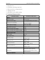
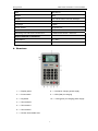
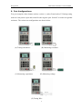
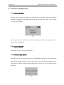
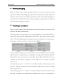
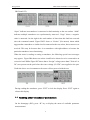
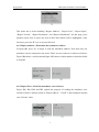
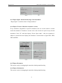
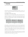
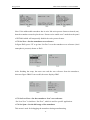
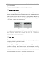
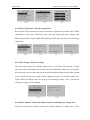
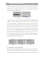
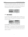
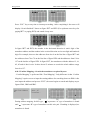
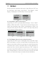
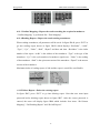
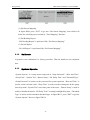
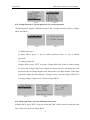
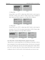
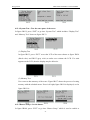
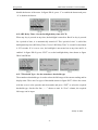
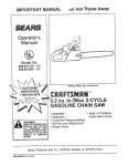
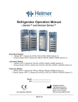
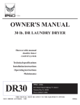
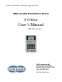
Cable Pressure Monitoring System
Addressable Transducer Tester
PVD860
User’s Manual
(P012190 - Rev. C)
226A Commerce St.
Broomfield, CO 80020
800.521.5351 303.427.3700
Fax: 303.657.2233
www.puregas.com
Table of Contents
1. Introduction................................................................. 1
2. Main Functions and Features...................................... 1
3. Technical Characteristics........................................... 2
4. Structure ..................................................................... 3
5. Test Configurations..................................................... 4
6. Functions and Operation............................................. 5
6.1
Tester startup........................................................................................ 5
6.2
Tester turnoff ........................................................................................ 5
6.3
Tester sleep mode ................................................................................. 5
6.4
Battery charging .................................................................................. 6
6.5
Reading a transducer........................................................................... 6
6.6
Reading other transducer parameters ................................................. 8
6.7
Sensor Setup....................................................................................... 11
6.8
Sensor Type Setup .............................................................................. 13
6.9
Pair Test ............................................................................................. 13
6.10 Address Mapping ............................................................................... 16
6.11 Data Report........................................................................................ 18
6.12 Calibrate ............................................................................................ 20
6.13 System Operate .................................................................................. 20
Puregas,LLC
Addressable Transducer Tester PVD860
1. Introduction
The PVD860 is a portable addressable transducer tester designed to automatically test,
program and calibrate a variety of addressable transducers. This tester is able to calibrate
addressable transducers on the production line and to make its production easier. And
also, it can test the transducers installed in the field to check the operational status of
these transducers. Besides, it can measure wire resistance, capacitance, and voltage to
verify the quality and suitability of the reporting pair(s). In order to make an addressable
transducer work properly, one can use this tester to set up the address for each transducer.
With the tester LCD display, test data can be displayed and monitored. The PVD860 is
portable, reliable, accurate and above all, easy to operate. It can be used as an all in one
instrument for installation and maintenance of addressable transducers.
2. Main Functions and Features
¾ High Accuracy and high resolution
¾ 128*64 LCD display, 4*4 keyboard
¾ Test the addressable transducers before and after installation
¾ Calibrate transducers on the production line
¾ Transducer address setup and verify
¾ Measure wire voltage, insulation and capacitance
¾ Test wire pair balance
¾ Measure transducer answer current and quiescent current including maximum and
minimum values
¾ Detect the address on pairs and display its voltage wave
¾ Average scanning time of 3 seconds per transducer
¾ Pair search mode to determine active addresses(multi-mode search)
¾ Data report function
¾ Optional password feature
¾ Extensive diagnostic facilities
¾ Real clock to display year, month, day, hour, minute and second
1
Puregas,LLC
Addressable Transducer Tester PVD860
¾ Auto power save
¾ NiCad battery with charge supervision
¾ Short circuit and over voltage protection
¾ Lightning protection
¾ Audio Beeper to give audible warnings
3. Technical Characteristics
PARAMETERS
CHARACTERISTICS
Power
Operational Voltage
DC3.3V ± 0.05V
Operational Power Supply
4 AA rechargeable battery with 1600mAh
8 hours continuous operation
Operational Time with Battery
240 hours for sleeping
Power Adaptor (recharging)
DC12V ± 2V,500mA
Recharging Time
<4 hours
Static Power Consumption
15 mW
Power Consumption with backlight
75 mW
Power Consumption with transducer operation
300 mW
Power Consumption for Sleeping
2 mW
Measurement Index
Output voltage
50V ± 2V
Max. Output Current
20mA
Range: 5V ~ 95V
Measuring Voltage
Accuracy: ± 0.5V
Range: < 15mA
Measuring Current
Resolution: 4uA
Range: < 10MΩ
Measuring Resistance
Accuracy: ±%1 (< 500 kΩ)
Range: < 100uF
Measuring Capacitance
Accuracy: ± 0.2uF
Measurement Accuracy for Transducers
± 0.5‰
Save 40 times result for searching
transducers and 200 detailed records for
Data Memory
reading transducers
Physical Properties
2
Puregas,LLC
Addressable Transducer Tester PVD860
Size
180*100*33
Weight
400 g
Display
LCD 128*64 matrix dots with backlight
Keyboard
4*4 keys
Language
English
Power Socket
DC power jack
Power Switch
Pushbutton switch
Monitoring Pair and Ground Connectors
3 Banana Socket with 3 Test Pens
Environmental Conditions
Temperature
0℃~60℃
Relative Humidity
0 to 80%Rh non-condensing
4. Structure
1 ——Display panel
8 ——Socket for charging power supply
2 ——Power switch
9 ——LED (Red) for charging
3 ——Keyboard
10 ——LED (green) for charging power supply
4 ——Test socket B
5 ——Test socket A
6 ——Test socket E
7 ——Sensor write-enable zone
3
Puregas,LLC
Addressable Transducer Tester PVD860
5. Test Configurations
Test port comprises three banana sockets: socket A, socket B and socket E. During testing
socket A is the positive pole and socket B is the negative pole. Socket E is used to test ground
resistance. The various test configurations are shown below:
(B) Measuring resistance
(A) Testing transducers
(C) Measuring capacitance
(D) Measuring voltage
(E) Testing Wire
4
Puregas,LLC
Addressable Transducer Tester PVD860
6. Functions and Operation
6.1 Tester startup
Push the power switch down and tester will start in two seconds. After that, the panel
displays the homepage as the following fig. IB1. In any term, press “ESC” once or more
to exit to the homepage.
In the top-left corner current date and time are displayed. In the top-right corner, the
battery meter is displayed.
6.2 Tester turnoff
Release the power switch to turn off tester.
6.3 Tester sleep mode
When the tester is not operated for the user programmed sleep time, it will go into sleep
mode during which all functions will be shut down and it will consume minimal power.
Sleep mode is shown as the following figure IB151. Press any key to resume normal
operation.
5
Puregas,LLC
Addressable Transducer Tester PVD860
6.4 Battery charging
When the battery meter on the homepage indicates less than one segment, normal
operation is inhibited and recharging is required. Push the plug of the charge adaptor into
the charge socket of the tester and the green LED will come on to indicate the charger is
connected. The red LED will come on whilst charging is in progress. The red LED will
switch off when charging is complete.
6.5 Reading a transducer
There are three methods to read the transducer: Read with its address, Auto-answer with
power-on and Answer with an order.
On the homepage, press numeric keys to input the address of the transducer. Refer to
figure IB39. Except for 882-ADR transducer like UTEL’s, their address must be smaller
than 128. For 882-ADR transducer, the address must be smaller than 64. Or else the tester
will indicate “Address Overflow” as shown in figure IB152.
After the address is input, press “R” key to begin to read transducer as shown in figure
IB40. Results for reading transducer are displayed as per figure IB153, IB154 and IB155.
Figure IB153 shows a normal read result whilst figures IB154 and IB155 show error
conditions. In these figures, “SysSpan” is the full-range to be set. “SysUnit” is the data
unit to be set.
On the homepage, press “↑” and “R” to read the transducer with Auto-answer with
power-on. This type of transducer can automatically send the answer current as a reading
after it is powered on.
On the homepage, press “↓” and “R” to read the transducer with Answer with an order.
This type of transducer can automatically send the answer current as a reading after it
6
Puregas,LLC
Addressable Transducer Tester PVD860
gets an order from PVD860. For Dedicated Solid State Transducer, this method should be
used.
After reading the transducer, its results can be shown with different modes. Figure IB153
shows a normal result. In this figure, the top-left corner shows read progress. “Curr”
displays the latest reading. “Max” shows the maximum reading since the “read”
operation commenced and “Min” shows the minimum reading since the “read” operation
commenced. “I” is the answer current of the responding transducer. “Data” shows the
read value (such as air pressure or flow). For “I”, “Curr” is the latest value and “Max” and
“Min” are the highest and lowest values since the command was commenced. Taken
together the readings will provide a good indication of the stability and quality of the
readings being received. The fourth line of the display (figure IB153) shows the reading
status. The figure on the right of “Sum” is the total number of times the transducer has
been read since the command started and that on the right of “Fault” is the number of
errors that have occurred during that time. The bottom line shows the “addr” (address) of
the transducer being read. The bottom-right corner shows the type of transducer being
read which includes:
"881-PWR"
: Type 881/880, auto-answer with power-on;
"881-ORD"
: Type 881/880, answer with an order;
"881-ADR"
: Type 881/880, read with its address;
"882-PWR-A"
: Type 882, class A, auto-answer with power-on;
"882-PWR-B"
: Type 882, class B, auto-answer with power-on;
"882-ORD-A"
: Type 882, class A, answers with an order;
"882-ORD-B"
: Type 882, class B, answers with an order;
"882-ADR-A"
: Type 882, class A, read with its address;
"882-ADR-B"
: Type 882, class B, read with its address.
"SPN-PWR"
:Type SPAIN, auto-answer with power-on;
"SPN-ORD"
:Type SPAIN, answer with an order;
"SPN-ADR"
:Type SPAIN, read with its address;
When the transducer is reading OK, “Sum” is displayed in reverse color (as shown in
figure IB153). If an error is occurring then “Fault” is in reverse color (as shown in figures
7
Puregas,LLC
Addressable Transducer Tester PVD860
IB154 and 155).
“Open” indicates no transducer is connected or bad continuity to the test sockets. “Mult”
indicates multiple transducers are synchronously answered. “Nega” shows a negative
value is answered. On the right is the total number of times that this fault has occurred
since the command started. Figure IB155 shows a “NoAns” (No answer) alarm which
suggests that a transducer or similar load is connected to the test socket, but no answer was
received. This may be because there is no transducer with right address or because the
particular transducer in not functioning.
When the tester is reading or setting a transducer, the following special error messages
may appear: Figure IB6 shows test socket A and B to be shorted or to be connected to an
excessive load. Whilst Figure IB7 shows that a “foreign” voltage (more than 5 Volts AC or
DC) was present on the pair before the tester voltage (50 VDC) was applied to the pair.
Under the above two circumstances the tester will not proceed with the test.
During reading the transducer, press “ENT” to lock the display. Press “ENT” again to
release this display.
6.6 Reading other transducer parameters
On the homepage (IB2), press “R” key to display the menu of available parameter
measurements:
8
Puregas,LLC
Addressable Transducer Tester PVD860
This menu has 6 items including “Report Address”, “Report Zero”, “Report Span”,
“Report Version”, “Report Parameters” and “Report Information”. On this page, press
up/down arrow keys to select any item of this menu which will be highlighted. After
selection, press the “R” key to execute this item.
6.6.1 Report Address---Determine the transducer address
In figure IB2 press “R” to begin to read the transducer address. Note that only one
transducer can be connected to the tester! There are two results to be shown as follows:
Figure IB4 shows a valid result and figure IB5 shows a fault transducer which has failed
to respond.
6.6.2 Report Zero---Read the transducer zero reference
Figure IB8, IB9, IB10 and IB5 explain the progress of reading the transducer zero
reference which is similar to that of “Report address”. “ZeroP” is the transducer internal
zero reference value.
9
Puregas,LLC
Addressable Transducer Tester PVD860
6.6.3 Report Span---Read the full range of the transducer
“Report Span” is similar to that of “Report address”.
6.6.4 Report Version---Read the transducer version
Every transducer (depended on specific transducer) has one version which is written
inside the transducer. Transducer version can be read via the wire pair for any selected
transducer. Press “R” and then display “Please Input Addr”. After the transducer’s
address is entered the tester displays the transducer version shown as figure IB23, IB24,
IB25 and IB26.
6.6.5 Report Parameter
This menu is only for debugging the transducer during manufacturing.
6.6.6 Report Information
This menu is only for debugging the transducer during manufacturing.
10
Puregas,LLC
Addressable Transducer Tester PVD860
6.7 Sensor Setup
On the homepage IB1, press “W” to go into the main menu shown as figure IB30.
This main menu is composed of five submenus including “Set Address”, “Set Zero”, “Set
Low Zero”, “Set Span” and “Set Parameter” shown as IB30. Use up/down arrow keys to
select the required submenu.
6.7.1 Set Address---Set the transducer address
In figure IB30, press “W” to go into the transducer address program mode shown as
figure IB32. This prompts user to input the desired new address for this transducer. After
entering the correct address, press “W” to begin to write this address shown in figure
IB33. It must be noted that the address is less than 128 for 880/881 transducer and less
than 64 for 882 transducer.
After the address is written into the transducer, the tester will verify it automatically. If
the readout address from the transducer is the same as the written address, the tester
displays “Finished, OK!” shown as figure IB35 and sounds one long beep. If not, the
tester displays “Finished, ERROR!” as figure IB37 and sounds two short beeps and one
long beep. The second displayed address on these screens is that reads out from the
transducer shown on screen IB35 and IB 37.
The prompts at the bottom of figure IB35, IB36 and IB37 show the way in which
operation for address setup can be repeated or cancelled. In figure IB35, press “W” to set
next address (ID=107 shown as IB36) for next transducer.
11
Puregas,LLC
Addressable Transducer Tester PVD860
Note: If the addressable transducer has its wire link write-protect feature activated (cut),
then the transducer must be placed near “Sensor write-enable zone” marked on the panel
of PVD860 which will temporarily disable the write-protect feature.
6.7.2 Set Zero---Set the transducer zero reference
In figure IB42, press “W” to go into “Set Zero” to set the transducer zero reference (local
atmospheric pressure) shown as IB43.
After finishing the setup, the tester can read the zero reference from the transducer,
shown as figure IB44. If successful, the tester displays IB45.
6.7.3 Set Low Zero---Set the transducer “low” zero reference
“Set Low Zero” is similar to “Set Zero”, which is used for specific application.
6.7.4 Set Span---Set the full range of the transducer
This menu is used for debugging the transducer during manufacturing.
12
Puregas,LLC
Addressable Transducer Tester PVD860
6.7.5 Set Parameter
This menu is used for debugging the transducer during manufacturing.
6.8 Sensor Type Setup
On the homepage IB1, press “ENT” to go into the main menu shown as IB29. But it must
be noted that if the system password is enabled then the PVD860 will prompt the user to
input the system password. After this password is acknowledged, the IB29 will be
displayed which includes six submenus: “Sensor Type”, “Pair Test”, “Address Mapping”,
“Data Report”, “Calibrate” and “System Operate”.
On the IB29, select first item and press “ENT” to go into “Sensor Type” shown as IB172.
Here the type for transducer can be selected. After “ENT” key is pressed, this
transducer’s type is written in this transducer.
6.9 Pair Test
The tester can measure four parameters for the wire pairs connecting transducers:
resistance, capacitance, voltage and pair balance.
6.9.1 Wire Resistance---Measure resistance
In figure IB65, press “ENT” to go into IB66 and then press “ENT” again to begin
resistance measurement. Wire resistance includes three measurements: resistance
between socket A and B, resistance between socket A and E, resistance between socket B
and E. All measurements are done automatically. When the resistance to be measured is
more than 10 MΩ, the tester displays “> 10Megohm” shown as figure IB67.
13
Puregas,LLC
Addressable Transducer Tester PVD860
6.9.2 Wire Capacitance---Measure capacitance
Based on RC time constant, the tester can measure capacitance less than 100uf. When
capacitance is more than 100uf, the tester will stop. Measuring time changes with
different capacitance. Figure IB68, IB69, IB70 and IB71 show the process of measuring
capacitance.
6.9.3 Wire Voltage---Measure voltage
The tester can measure the voltage ranged from 5 to 95Volts. Note that the voltage
between socket A and B must be less than 100Volts. When this voltage is over 100Volts,
the protection circuit for the tester port will operate and also output current of the external
source which provides this voltage will be rapidly increased. An accident could occur.
Figure IB160 and IB161 show the process of measuring voltage. Once a second the
reading of voltage will be updated.
6.9.4 Detect Address---Detect the address on pairs and display its voltage wave
The tester can detect the address on the pairs, and also display its voltage wave. First,
14
Puregas,LLC
Addressable Transducer Tester PVD860
hang the test hooks of PVD860 with socket A and B on the wire pairs. And then press
“ENT” in figure IB164 to start to detect the address on the pairs shown as figure IB165.
In figure IB165, the bottom line shows the voltage wave corresponded to the address sent
from the air pressure monitoring system.
If there is an address to be on the wire pairs, then figure IB166 will be displayed in which
“Address” is an address to be just detected on pairs and “Crest” is the voltage value of
wave crest and “Trough” is the voltage value of wave trough. The “14ms” shown in
figure IB166 represents that each dot of horizontal axis for address wave takes 14ms
(Note that each dot of vertical axis of address wave represents 2 volts). In figure IB166,
press “ENT” key to hold the viewing wave on as figure IB167 on the top-right of which
the reverse color “H” will be displayed. And press “ENT’ once more to cancel “hold on”.
During detecting, press different numeric keys to change time scale division of LCD
screen. Each dot time is 2 times the number of key with the unit of millisecond (Note that
key “0” represents 10). For example, press the key “5” to scale the wave wider shown in
figure IB168 (Its time scale division is 10ms).
6.9.5 Pair Balance---Test wire pair balance
The tester can test wire pair balance with the two voltages between pairs and ground.
First, hang the test hooks of PVD860 on wire pairs and ground according to figure E in
the section 5. And then press “ENT” in figure IB169 to start to test wire pair balance. The
15
Puregas,LLC
Addressable Transducer Tester PVD860
test results are shown in figure IB170. In this figure, “AVPer” is the ratio, with percent, of
the voltage between A and E to the voltage between A and B. “BVPer” is the ratio, with
percent, of the voltage between B and E to the voltage between A and B. “DifPer” is the
difference between “AVPer” and “BVPer”. “Dif” is the voltage between A and B. “AEV”
is the voltage between A and E. “BEV” is the voltage between B and E.
6.10
Address Mapping
The tester provides the convenient and intuitive function for searching for “lost”
transducers. The search results are automatically saved in the tester. The following
figures show the options of “Total Mapping” and “Confine Mapping”, which determines
how the pair is searched.
6.10.1 Total Mapping --- Search all transducers on the wire pair
In figure IB73, press “ENT” to the entire 0-127 address range on the wire pair. Searching
begins at address 0, 1, 2… and ends at address 127 shown as figure IB75 and IB76. In the
process of searching, a small square flashes. If any transducer with the related address
exists on the wire pair and is detected, the small square related with this transducer is
displayed as a solid block.
16
Puregas,LLC
Addressable Transducer Tester PVD860
Press “ESC” key at any time to interrupt searching. After completing it the tester will
display “Search finished!” shown as figure IB77 and IB78 (Use up/down arrow keys for
paging IB77 or paging IB78) and sound a beep once.
In figure IB77 and IB78, the number in the horizontal direction is unit’s digit of the
transducer address and the number in the vertical direction are its tens digit and hundreds
digit. For example, there are the addresses from 0 to 9 on the first line of figure IB77 and
the addresses from 70 to 79 on the first line of figure IB78 and the addresses from 120 to
127 on the last line of figure IB78. In figure IB77, the transducers with the address 12, 16,
42, 45 and 66 don’t exist. It takes about 15 minutes to search the whole address range
from 0 to 127.
6.10.2 Confine Mapping---Search the transducers required by user
“Confine Mapping” is performed like “Total Mapping”. Only difference is that “Confine
Mapping” requires a user to input the starting address for searching shown as IB80. After
user inputs the address and presses “ENT”, the tester begins to search and displays as per
figures IB81, IB82 and IB83.
During address mapping for 882 type, “
and “
” represents “A” type of transducer is found
” represents “B” type of transducer on this wire pair. If nothing is displayed, no
transducer is found.
17
Puregas,LLC
6.11
Addressable Transducer Tester PVD860
Data Report
The tester provides the comprehensive data reports. In figure IB84, press “ENT” to go
into “Data Report” which includes “System Report”, “Total Mapping”, “Confine
Mapping”, “Reading Report” and “Delete Report” shown as figure IB85.
6.11.1 System Report---Report system parameters
In figure IB85, press “ENT” to go into figure IB86 which displays “Version”, “BatVol”,
“BLTime”, “SPTime” and “OutVol”. “Version” in this case is the tester firmware version.
“BatVol” is the current battery voltage. “BLTime” is the backlight time. “SPTime” is the
waiting time before going into sleep mode. “OutVol” is the output voltage between
socket A and B while testing the transducer.
6.11.2 Total Mapping---Report the result searching all transducers
In figure IB54, press “ENT” to go into “Total Mapping” shown as figure IB55. In figure
IB55, the first number of every line is the index number for data report and its next
numbers are date and time at which the wire pairs begin to be searched. Maximum index
is 24 and the report is saved as a scroll buffer. NULL is an index without data. Use
up/down arrow keys to select the required item and then press “ENT” to display the
report shown as figure IB162 and IB163(use up/down arrow keys to page up and page
down). Existing transducers are shown with a solid square in the panes with related
address, or else with a hollowed square (no transducer detected at that address).
18
Puregas,LLC
Addressable Transducer Tester PVD860
6.11.3 Confine Mapping---Report the result searching the required transducers
“Confine Mapping” is performed like “Total Mapping”.
6.11.4 Reading Report---Report the result reading transducers
When reading a transducer, all parameters will be saved. In figure IB149, press “ENT” to
go into reading report shown as figure IB150 which displays “RecIndex”, “Addr”,
“Type”, “Cyc”, “Value”, “StatI”, “DynaI” and date and time. “RecIndex” is the index
number of the report. “Addr” is the address of the transducer. “Type” is the type of the
transducer. “Cyc” is the cycle number of transducer signal wave. “Value” is the reading
of the transducer. “StatI” is the quiescent current of the transducer. “DynaI” is the answer
current of the transducer.
Maximum index of reading reports is 200 and the report is saved like scroll buffer.
6.11.5 Delete Report---Delete the existing report
In figure IB87, press “ENT” to go into deleting report. Note that user must input
password before deleting report shown as figure IB27. After the correct password is
entered, the tester will display figure IB88 which includes four items: “Del Sensor
Mapping”, “Del Reading Report” and “Del All Report”.
19
Puregas,LLC
Addressable Transducer Tester PVD860
(1) Del Sensor Mapping
In figure IB88, press “ENT” to go into “Del Sensor Mapping” item which will
delete the searching report created by “Total Mapping” function,.
(2) Del Reading Report
“Del Reading Report” is performed like “Del Sensor Mapping”.
(3) Del All Report
“Del All Report” is performed like “Del Sensor Mapping”.
6.12
Calibrate
In general, tester calibration is a factory procedure. Thus the details are not explained
here.
6.13
System Operate
“System Operate” is a setup menu composed of “Setup Password”, “Date and Time”,
“Sleep Time”, “System Test”, “Buzzer Setup”, “BL Delay Time” and “Threshold Type”.
“Setup Password” is used to set the password for system operation. “Date and Time” is
used to set the real-time clock. “Sleep Time” is used to set the waiting time before going
into sleep mode. “System Test” tests some parts of the tester. “Buzzer Setup” is used to
enable or disable the buzzer. “BL Delay Time” is setting backlight delay time. “Threshold
Type” is used to set the transducer threshold type. In figure IB113, press “ENT” to go into
“System Operate” shown as figure IIB114.
20
Puregas,LLC
Addressable Transducer Tester PVD860
6.13.1 Setup Password---Set the password for system operation
“Setup Password” includes “Enable Password” and “Change Password” shown as figure
IB115 and IB116.
(1) Enable password
In figure IB116, press “3” key to enable password. Press “6” key to disable
password.
(2) Change password
In figure IB119, press “ENT” to go into “Change Password” which is used to change
the password. In figure IB120, user inputs new password once and inputs the same
password again to change the password. Password is a six-digit number. If the input
password is right, the tester displays “Change success!” shown as figure IB120. If it
is wrong, displays “Input error!” shown as figure IB121.
6.13.2 Date and Time---Set date and time of the tester
In figure IB122, press “ENT” to go into “Date and Time” which is used to set the date and
time of the tester shown as figure IB123.
21
Puregas,LLC
Addressable Transducer Tester PVD860
(1) Change Date
In figure IB123, press “ENT” to display figure IB124 which is used to input the
current date. If today is Jun.8, 2004, for example, input the digit of 20040608. If
input is right, figure IB124 is displayed, or else figure IB125 is displayed.
(2) Change Time
In figure IB126, press “ENT” to display figure IB127 which is used to input the
current time. If it is 10:32:29, for example, input the digit of 103229. If input is right,
figure IB127 is displayed, or else figure IB128 is displayed.
6.13.3 Sleep Time---Set the waiting time before going into sleep status
When the tester is in the sleeping status, all of its functions are shut down so that its
power consumption is least to make operating time longer. After the tester is not operated
by user for the sleeping time, the tester goes into the sleeping status. In figure IB129,
press “ENT” to go into “Sleep Time” shown as figure IB130 which is used to input the
sleeping time (from 30 to 3600 seconds). Under sleeping status, press any key to quit.
22
Puregas,LLC
Addressable Transducer Tester PVD860
6.13.4 System Test---Test the some parts of the tester
In figure IB132, press “ENT” to go into “System Test” which includes “Display Test”
and “Memory Test” shown as figure IB133.
(1) Display Test
In figure IB133, press “ENT” to test the LCD of the tester shown as figure IB134
(black color) and IB135 (gray color) to make user estimate the LCD. If a stain
appears on the LCD, then the display may be defective.
(2) Memory Test
User can test data memory of the tester. Figure IB137 shows the process of testing
memory with the schedule meter. If test is all right, figure IB138 is displayed, or else
figure IB139 is.
6.13.5 Buzzer Setup---Set the buzzer
In figure IB140, press “ENT” to go into “Buzzer Setup” which is used to enable or
23
Puregas,LLC
Addressable Transducer Tester PVD860
disable the buzzer of the tester. In figure IB141, press “3” to enable the buzzer and press
“6” to disable the buzzer.
6.13.6 BL Delay Time---Set the backlight delay time of LCD
When any key is pressed at any time, the backlight is turned on. But if no key is pressed
for a period of time, it is automatically turned off. This “period of time” is called the
backlight delay time (BL Delay Time). Unit of “BL Delay Time” is second. Its maximum
is 255 seconds. If it is set to zero, the backlight is not turned on at any time until it is
enabled. In figure IB142, press “ENT” to set the backlight delay time shown as figure
IB143 and IB144.
6.13.7 Threshold Type---Set the transducer threshold type
The transducer threshold type is used to select the full-range of the current reading and its
display units. There are five types of thresholds shown in figure IB173. Move the cursor
with the reverse color upwards and downwards and press “ENT” to select the required
threshold type. On the first line, “----” shows no unit. In “User” column, the required
full-range can be input.
January 16, 2008
24