1
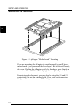
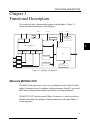
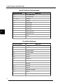
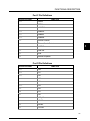
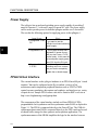
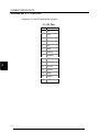
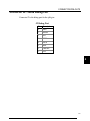
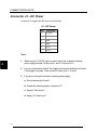
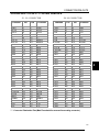
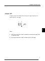
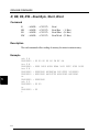
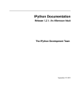
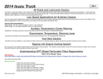
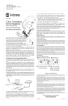
Hardware Reference Manual Hardware Reference Manual Notice The information in this document is subject to change without notice. THE SOFTWARE AND DOCUMENTATION ARE PROVIDED "AS IS" WITHOUT WARRANTY OF ANY KIND INCLUDING WITHOUT LIMITATION, ANY WARRANTY OF MERCHANTABILITY OR FITNESS FOR A PARTICULAR PURPOSE. FURTHER, Bright Star Engineering DOES NOT, GUARANTEE, OR MAKE ANY REPRESENTATIONS REGARDING USE, OR THE RESULTS OF THE USE, OF THE SOFTWARE OR WRITTEN MATERIAL IN TERMS OF CORRECTNESS, ACCURACY, RELIABILITY, OR OTHERWISE. Restricted Rights Legend Use, duplication, or disclosure by the United States Government is subject to restrictions as set forth in subparagraph (c)(1)(ii) of the Rights in Technical Data and Computer Software clause at DFARS 252.227-7013. This document may not, in whole or in part, be copied, reproduced, translated, or reduced to any electronic medium or machine readable form without prior consent, in writing, from Bright Star Engineering, Inc. Bright Star Engineering, Inc. All Rights Reserved Printed in the USA November 1998 &RQWHQWV CHAPTER 1 IPENGINE OVERVIEW .................................................................................... 1-1 THE IPENGINE VIRTUAL INTERFACE.......................................................................................... 1-2 CHAPTER 2 SETUP AND OPERATION ................................................................................ 2-1 REQUIRED HARDWARE .............................................................................................................. 2-2 UNPACKING THE IPENGINE ........................................................................................................ 2-3 MOUNTING THE IPENGINE ......................................................................................................... 2-4 CONNECTING A POWER SOURCE................................................................................................ 2-5 CONNECTING ETHERNET AND RS-232....................................................................................... 2-6 CONFIGURING THE NETWORK CONNECTION ............................................................................. 2-6 TESTING NETWORK OPERATION ................................................................................................ 2-8 WHAT COMES NEXT.................................................................................................................. 2-9 CHAPTER 3 FUNCTIONAL DESCRIPTION ........................................................................ 3-1 MOTOROLA MPC823 CPU ....................................................................................................... 3-1 FLASH AND DRAM MEMORY ................................................................................................... 3-3 POWER SUPPLY ......................................................................................................................... 3-6 FPGA VIRTUAL INTERFACE ...................................................................................................... 3-6 CHAPTER 4 CONNECTOR PIN-OUTS.................................................................................. 4-1 OVERVIEW ................................................................................................................................ 4-1 CONNECTOR J1 – I/O PORT ....................................................................................................... 4-2 CONNECTOR J2 – BDM DEBUG PORT ....................................................................................... 4-3 CONNECTOR J3 – DC POWER.................................................................................................... 4-4 CONNECTORS J10 & J11- VIRTUAL INTERFACE ........................................................................ 4-5 VIRTUAL INTERFACE PIN FUNCTION ......................................................................................... 4-6 JUMPER JP1 ............................................................................................................................... 4-7 CHAPTER 5 IPENGINE FIRMWARE.................................................................................... 5-1 OVERVIEW ................................................................................................................................ 5-1 R, RB, RS, RW – READ BYTE, SHORT, WORD ......................................................................... 5-2 W, WB, WS, WW – WRITE BYTE, SHORT, WORD ................................................................... 5-3 FGET – GET PARAMETER ......................................................................................................... 5-4 FSET – SET PARAMETER .......................................................................................................... 5-5 LOAD – TFTP FILE LOAD........................................................................................................ 5-6 FLOAD – FPGA CONFIGURATION TFTP LOAD ....................................................................... 5-7 GO – JUMP TO ADDRESS ........................................................................................................... 5-8 REBOOT – REBOOT SYSTEM ................................................................................................... 5-9 FERASE – ERASE FLASH MEMORY........................................................................................ 5-10 I STANDARD PARAMETER VALUES ................................................................................................ 5-11 CHAPTER 6 ELECTRICAL SPECIFICATIONS .................................................................. 6-1 CHAPTER 7 THERMAL SPECIFICATIONS ........................................................................ 7-1 CHAPTER 8 MECHANICAL SPECIFICATIONS................................................................. 8-1 APPENDIX A RELATED DOCUMENTS………………………………………………….…...I APPENDIX B TFTP SERVER SETUP………………………………………………………...III II IPENGINE OVERVIEW Chapter 1 ipEngine Overview 1 Bright Star Engineering’s ipEngine credit-card sized processor module provides an ideal core for a network enabled product. The ipEngine utilizes the Motorola PowerPC MPC823 processor with an array of on-chip peripherals including Ethernet, USB, LCD/Video, I2C and serial controllers. The on-board flash memory file system provides storage for the operating system as well as OEM application software and data. The ipEngine-1 has the following significant features: • • • • • • • • • • 66 MIPS Power PC CPU 16 MB DRAM 4 MB FLASH 10Base-T Ethernet On-board 16- Watt Power Supply 16,000 Gate FPGA Virtual I/O Interface USB Host/Slave Controller LCD/Video Controller Dual RS-232 The external interface to the ipEngine hardware is via an FPGA-based "virtual interface" which can be configured on the fly to adapt to the OEM's needs. The FPGA can be configured to emulate a variety of bus architectures as well as to implement peripheral functions like UARTs, PWM control, memory emulation, data capture and synthesis, and interfaces to a variety of input devices. The ipEngine provides a firmware boot loader programmed into the flash memory "bootblock" at the factory. The bootloader is used to initialize the ipEngine and load the primary operating system from flash memory, from the network or from the serial console. The ipEngine includes a run-time license for BSE's pKernel real-time network operating system. The ipEngine can also be readily used with other operating systems like VxWorks, Windows CE, PSOS, QNX, eCos or Linux. 1-1 1 IPENGINE OVERVIEW When combined with BSE’s pKernel software environment, the ipEngine can significantly reduce the time, cost and complexity required to "network enable" a product by providing a vertically integrated "network engine" complete with the required hardware, software, and development environment. By employing POSIX and ANSI C standards, the ipEngine's pKernel software environment leverages a familiar programming environment and facilitates migration of software from UNIX and Windows 95/NT platforms. The pKernel SDK provides an integrated development environment based upon the industry standard GNU tool chain. The software developer’s toolkit includes the gcc cross-compiler, a linker, archive librarian and other utilities. Source level over-the-network debugging of code running on the target system is accomplished via a thread aware version of the GNU GDB debugger. The ipEngine Virtual Interface The ipEngine’s virtual interface consists of 88 I/O pins that do whatever you want them to. This reduces integration time and cost in two ways: • Adapt the ipEngine to your existing product. You can use existing I/O in your product to communicate with the ipEngine. • Use the ipEngine to control and monitor your hardware. This might enable you to replace your existing controller entirely, or save you from having to build or buy additional I/O and control modules. Suppose you currently make a small control device that is commanded by a matrix keypad. You want to sell the same product with a network command interface. This is easy to do with the ipEngine: Remove the matrix keypad from your product. • Define a matrix keypad interface in the FPGA configuration of the ipEngine, and connect it to the old keypad input in your product. • Write a small command processor software module for the PowerPC in the ipEngine. Have it accept network commands in whatever form you’d like (telnet, JAVA, CORBA, HTML, 1-2 IPENGINE OVERVIEW C/C++), and translate these into matrix keyboard “presses” that are output to the virtual interface. You define a virtual interface by configuring the on-board FPGA. FPGA configurations are automatically built at BSE by a script driven process which assembles and tests a particular configuration from our internal library of interface sub-components. Below are two examples of a virtual interface you might be able to configure: Example 1 Example 2 1 8 Bit Bus 1 8 Bit ROM/RAM emulator 3 Serial/UART Ports 20 General Purpose I/O 8 PWM Outputs 8 Quadrature decoders 2 Stepper Motor Controllers 1 Waveform synthesizer 1 Keypad interface 1 Segmented LED driver 4 Serial A/D interface 6 Timers 4 Serial D/A interface 1 ISA Bus slave interface You can also make custom configurations using elements not in the fpgaWare library, using Altera’s no-cost FPGA development tools. The ipEngine is powerful enough to serve as a stand-alone embedded machine or instrument controller. The virtual interface provides an extraordinary quantity and flexibility of I/O. The power of the virtual interface really shines, though, when it saves you integration time and money. You can use the I/O to wrap your existing product with a local communication connection, and use the PowerPC to connect to the rest of your network. 1-3 1 IPENGINE OVERVIEW 1 1-4 SETUP AND OPERATION Chapter 2 Setup and Operation This chapter shows you how to get your ipEngine out of the shipping box and begin to use it. The steps you’ll follow are: • Unpack the board. • Mount the ipEngine on a motherboard or other chassis (this step is optional). • Connect power. • Connect Ethernet and a serial port. • Set parameters in the flash memory of the ipEngine to define power-up behavior. • Verify correct operation. • Begin downloading software, and start development work and testing. 2-1 2 SETUP AND OPERATION Required Hardware You need the following equipment to begin using the ipEngine: 2 • The ipEngine board itself. • Power source. An unregulated source of 7-18 volts DC is required. You can use a simple wall-plug power module for this purpose. • Ethernet and serial cables, with connectors appropriate for your configuration. • At least one host computer with an Ethernet connection. You’ll use the host computer to set the connection parameters of the ipEngine, download software, and to debug its operation. • Software on the host computer. This includes: • Terminal emulator. This enables you to configure the ipEngine via its serial port. • TFTP (Trivial File Transfer Protocol) server. (The PumpKIN TFTP server is freely available from BSE.) 2-2 SETUP AND OPERATION Unpacking the ipEngine You need to use precautions to avoid electrostatic discharge (ESD) damage to the ipEngine. You should wear a properly grounded antistatic wrist strap before removing the ipEngine from its protective antistatic envelope, and whenever you touch it. The ipEngine should always be kept on a grounded, static-free surface. We recommend that you keep the ipEngine in an ESD-approved workstation for your development work. If the shipping carton is damaged when you receive it, the shipper may be liable for damages. To ensure that you can be reimbursed for damage in shipping, make sure that the shipper or their agent is present when you unpack and inspect the equipment. Using ESD-safe procedures, remove all equipment from the packaging material. Check the packing list to make sure all items have been included. . 2-3 2 SETUP AND OPERATION Mounting the ipEngine 2 Figure 1-1. ipEngine “Motherboard” Mounting If you are mounting the ipEngine to a motherboard (you will have a motherboard if you purchased the Developer’s Kit or the netChassis), do it now. Holding the ipEngine gently by the edges, press firmly on connectors J10 and J11 until the ipEngine is completely seated For prototype development, you may also be using the J10 and J11 connections, but not on a motherboard. If so, mate each connector firmly, making sure to observe ESD safety. 2-4 SETUP AND OPERATION Connecting a Power Source If you purchased the netChassis, just plug the chassis’s power module into a 110V AC receptacle, connect the DC power jack to the netChassis, and you’re done. You can proceed to the next section. You can supply power to the ipEngine in several different configurations: Input Power Why? JP1 Jumper Setting Connections Remove all jumpers Ground to J3-4 & J3-5 1. Unregulated 7-18V If you want to use the from JP1 +DC to J3-5 & J3-6 DC ipEngine’s on-board switching power supply. 2. Regulated 5V DC 3. Regulated 5V and 3.3V DC If your system already has a Connect pins 1-2 regulated 5V power source, Disconnect pins 3-4 and you don’t have a 7V DC source handy. In this case the on-board power supply generates 3.3V from the 5V input. Disconnect pins 1-2 Use this configuration if switching noise is a concern, Connect pins 3-4 and you wish to completely disable the on-board supply. Ground to J3-4 & J3-5 +5V to J3-1, J3-5, J3-6 Ground to J3-4 & J3-5 +5V to J3-1 +3.3V to J3-2 Don’t connect J3-5 & J3-6 Before applying power, set the jumper block JP1 to correspond to your configuration. If you are mounting the ipEngine to your own motherboard, you can supply power via connectors J10 and J11, instead of using J3. See Section 4 for the pin assignments for J10 and J11. 2-5 2 SETUP AND OPERATION Connecting Ethernet and RS-232 If you purchased the netChassis, plug a standard 10BaseT Ethernet cable into the chassis connector; plug the other end into the network connector of your host computer. Connect a serial cable with RJ11 connector into the chassis connector RS232-1; plug the other end into a serial port connector of your host computer. The ipEngine is configured as DTE. 2 If you do not have a netChassis, you can also make your Ethernet connection directly to connector J1, pins 1 through 6. Connect to serial port 1 using J1-9 (TX) and J1-10 (RX). See Chapter 4 for the pin assignments for J1. Configuring the Network Connection The first time you use the ipEngine, you must either set network parameters to its flash memory, or have a DHCP/BOOTP server setup to supply the appropriate parameters to the ipEngine upon bootup. This allows it to initialize and boot correctly from then on. In your product configuration, you’ll have several options for downloading. This section shows you only one option, manually configuring an IP address. We recommend you try this, at least the first time you use the ipEngine, because it allows you to quickly verify that it has a correct Ethernet connection. In this session, you’ll define the following parameters: • • • • IP address of the ipEngine. Network netmask. Host name of the TFTP server. Gateway IP address (optional). Before starting, determine the values of the parameters that you’ll use for this session. Your host computer will probably act as the TFTP server, so you’ll need its IP address. In the example below the TFTP server has address 192.168.1.150, the gateway address is 192.168.1.1, the netmask is 255.255.255.0, and we’ll assign the ipEngine the address 192.168.1.8. Start the terminal emulator on your host computer, and connect to your 2-6 SETUP AND OPERATION serial port. Press <return> to get a prompt. You can also cycle power to the ipEngine, or press its manual reset, to get a boot prompt. If you don’t receive characters by this point, carefully check all connections. Also make sure that your serial port is correctly configured. The ipEngine is shipped with these default serial parameters: 9600 baud, no parity, 8 bits, no stop bit. You might also need to swap the TX and RX pins on one side of your serial cable, or get a “gender- changer” connector. 2 Define the parameters by typing the following: >fset >fset >fset >fset myip 192.168.1.8 netmask 255.255.255.0 serverip 192.168.1.150 gateway 192.168.1.1 Verify the parameters by displaying them using the get command. Here’s an example: >fget myip = 192.168.1.8 netmask = 255.255.255.0 serverip = 192.168.1.150 gateway = 192.168.1.1 > 2-7 SETUP AND OPERATION Testing Network Operation You can now test that the ipEngine is properly hooked up to the network. From your host computer, run a “ping” test. On your have host computer, type: % ping 192.168.1.8 If you receive a response without timing out, the ipEngine is ready to go. If not, make sure that your host computer’s network connection is functioning properly. Make sure no other computer on the network is using the IP address you assigned to the ipEngine. 2 If you purchased the Developer’s Kit, you can perform a more complete checkout of the ipEngine. Make sure you have installed the software included with the kit on your host computer. Now, from your terminal window, download the first test program and run it, by typing: >load checkout.bin 4000; go 4000 You should see, in your terminal window, a long diagnostic output that shows you what the checkout program is doing. It will also write to the second RS-232 port; you may want to start another terminal window to check that the output from that port was also received (assuming you have made a physical connection to that port). Look over the diagnostic output. Warning or error messages indicate conditions that you should try to correct. 2-8 SETUP AND OPERATION What Comes Next Now you’ll begin configuring the ipEngine for your particular product. You’ll also begin developing and testing your software after that. The ipEngine supports many different options for configuration and development. In particular: • • You can manually configure the IP address of the ipEngine. This address stays in flash RAM forever, until you change it. You can configure the ipEngine to work with a DHCP server. In this case, the ipEngine obtains an IP address from the server each time it powers up. 2 There are several ways for you to develop software for the ipEngine. Your finished program will have two parts: • A PowerPC program that’s loaded into flash memory. • An FPGA configuration that’s loaded into the gate array. You can load flash memory in a variety of ways: • As a binary file obtained via TCP/IP from your TFTP server. • As an S-record file obtained from the TFTP server. • As an S-record file loaded from a serial port. Of course, your product may have dynamic functionality, and it can be configured to boot dynamically from the network each time it powers up. 2-9 SETUP AND OPERATION 2 2-10 FUNCTIONAL DESCRIPTION Chapter 3 Functional Description This section provides a functional description of the ipEngine-1. Figure 3-1 depicts the internal architecture of the ipEngine-1: DEBUG 5V 3.3V CLOCKS 7-18V DC XTAL CLOCK GEN LCD CTRL Switching Power Supply I2C 3 Motorola MPC823 USB ETHERNET SERIAL 1 SERIAL 2 FPGA 88 XCVR 2 MB FLASH XCVR 16 MB DRAM RS-232 64K z 16 SYNC SRAM Figure 3-1. ipEngine Architecture Motorola MPC823 CPU The MPC823 microprocessor, is low-cost yet enhanced version of the PowerPC family of microprocessors. It combines a high-performance PowerPC core with a RISC-based communication module and a variety of on-chip peripherals. The MPC823 SCC2 and an external 10Base-T transceiver is used to provide an ethernet connection to the ipEngine. Ethernet connections other than 10Base-T are not supported. 3-1 FUNCTIONAL DESCRIPTION The MPC823 SCC1 and associated USB transceiver is used to provide a master or slave USB interface to the ipEngine. Note that the MPC823 only supports 12 MBs transfer (high-speed) mode as a USB master. The USB data signals need to be terminated by the user for the appropriate master or slave configuration. The user must also supply appropriate bus power and short-circuit protection if the USB master is to supply power to the USB bus. The MPC823 SMC1 and SMC2 ports are used to provide a dual RS-232 serial interface to the ipEngine. The serial ports do not support hardware flow control via RTS/CTS. The MPC823 LCD/Video controller pins are connected directly to connector J10. These may be used as general purpose I/O signals when the LCD interface is not being used. Refer to the MPC823 User’s manual for further information on use and programming of the LCD/Video Interface. 3 The I2C bus signals are available on J10. These may be used as general purpose I/O signals when not being used for I2C. These signals have 4.7K pullup resistors on them. The MPC823 Serial Peripheral Interface (SPI) and PCMCIA functions are not available for use on the ipEngine. The MPC823 has a variety of on-chip features to support low power operation. The ipEngine further supports low-power board operation by proving means for shutting down various devices on the board including the Ethernet, USB and RS232 transceivers. All on-board memory devices also support low-power operation. 3-2 FUNCTIONAL DESCRIPTION Table 3-1 depicts the memory map for the ipEngine-1: ipEngine-1 Memory Map Address Range Description 0000.0000 – 00FF.FFFF 16 MB DRAM FC00.0000 – FC7F.FFFF 8MB FPGA Space FE00.0000 – FE3F.FFFF 4 MB FLASH FF00.0000 – FF00.3FFF MPC823 On-Chip Registers FF01.0000 – FF01.0000 FPGA Config Register FF02.0000 – FF02.0000 Clock Synth Reg 3 Flash and DRAM Memory The on-board 2M (1Mx16), BootBlock FLASH memory provides storage for the operating system as well as OEM application and data. The lowest two memory blocks are the "boot" blocks that are factory programmed with the boot monitor software, board serial number, and Ethernet MAC (hardware address). These blocks are locked and cannot be erased or reprogrammed. This is to ensure there is always some way to reload the board in case all the other flash block is erased or have been loaded with faulty code. Blocks 2 and 3 are used for parameter storage. These parameters, such as the IP address for the board and others, are used by the boot monitor software. See Chapter 5 for a complete description of the parameters used by the boot monitor. The following four tables specify the connection between the MPC823 multifunction ports A-D and specific ipEngine signals/functions: 3-3 FUNCTIONAL DESCRIPTION Port IP and Port A Pin Definitions MPC823 Pin Name 3 FUNCTION IP_B1 FPGA CONF DONE IP_B2 FPGA nSTATUS PA15/USBRXD USB RXD PA14 USB OE PA13 Ethernet RXD PA12 Ethernet TXD PA9 Serial 2 RXD PA8 Serial 2 TXD PA7 Ethernet TX Clock PA6 Ethernet RX Clock PA5 VCLK PA4 BCLK Port B Pin Definitions MPC823 Pin Name 3-4 FUNCTION PB31 LCD_A PB30 VCLKEN PB29 Ethernet Enable PB28 RS-232 Enable PB27 I2CSDA PB26 I2CSCL PB25 Serial 1 TX PB24 Serial 1 RX PB23 SDACK1 PB22 SDACK2 PB19 LCD_B PB18 Ethernet TX Enable PB17 LCD_C PB16 Ethernet Full-Duplex Enable FUNCTIONAL DESCRIPTION Port C Pin Definitions MPC823 Pin Name FUNCTION PC15 DREQ1 PC14 DREQ2 PC13 nCONFIG PC12 USBSPD PC11 USBRXP PC10 USBRXN PC9 Ethernet Collision PC8 Ethernet Carrier Detect PC7 USBTXP PC6 USBTXN PC5 PDN PC4 Ethernet Loopback 3 Port D Pin Definitions MPC823 Pin Name FUNCTION PD15 LD8 PD14 LD7 PD13 LD6 PD12 LD5 PD11 LD4 PD10 LD3 PD9 LD2 PD8 LD1 PD7 LD0 PD6 LCD_AC PD5 VSYNC PD4 HSYNC PD3 LCDCLK 3-5 FUNCTIONAL DESCRIPTION Power Supply The ipEngine has an on-board switching power supply capable of providing 2 amps of current at 3.3 volts and 2 amps of current at 5 volts. The power supply can be used to provide power for both the ipEngine and the user’s electronics. The user has the following options for supplying power to the ipEngine-1: Input Power Why? 1. Unregulated 7-18V If you want to use the DC ipEngine’s on-board switching power supply. 3 2. Regulated 5V DC 3. Regulated 5V and 3.3V DC If your system already has a regulated 5V power source, and you don’t have a 7V DC source handy. In this case the on-board power supply generates 3.3V from the 5V input. Use this configuration if switching noise is a concern, and you wish to completely disable the on-board supply. FPGA Virtual Interface The external interface to the ipEngine hardware is an FPGA-based 88-pin “virtual interface” that can be configured on the fly to emulate a variety of bus architectures and to implement peripheral functions such as UARTs, PWM control, memory emulation, data capture and synthesis, and interfaces to a variety of input devices. Sample FPGA source code can be found on BSE’s web site at http://www.brightstareng.com/fpgsamp.htm. The components of the virtual interface include an Altera EPF6016 FPGA, programmable clock synthesizer and fast synchronous static RAM. as depicted in Figure 3-1. The FPGA is connected directly to the PowerPC bus. The 128Kx16 synchronous burst static RAM is connected directly to the FPGA and can be used as shared buffer storage for data synthesis and acquisition applications. The synchronous nature of the SRAM simplifies the logic for the interface between 3-6 FUNCTIONAL DESCRIPTION the FPGA and SRAM and allows very high speech reading/writing of the SRAM. The clock synthesizer is used to generate arbitrary clock frequencies and its output is fed to both the Power PC and FPGA. Clock Architecture The clock architecture of the virtual interface logic is depicted in Figure 3-2. The four clock lines, VCLK, BCLK, UCLK and CPUCLK all feed the dedicated inputs of the EPF6016 which drive low skew global nets within the FPGA. These four low skew nets are typically used for chip global clocks, clock enables, resets and clears. The PowerPC outputs PA5 and PA6 are connected to VCLK and BCLK respectively. The PA5 and PA6 signals can be programmed to be clock outputs, clock inputs or general purpose I/O. The output of the clock synthesizer can be disabled via the VCLKEN signal. The 48 MHz MPC823 CPU clock is fed to both the FPGA and the Virtual Interface. The CPUCLK signal output can also be disabled. 9&/. %&/. 8&/. &38&/. 3$ 33& 3$ &ON 6\QWK 9LUWXDO,QWHUIDFH &RQQHFWRU )3*$ Figure 3-2. Clock Architecture The ipEngine’s clock synthesizer is the ICS AV9110 PLL based programmable asynchronous clock generator. The motivation providing an asynchronous clock generator is to allow the generation of clock frequencies other than those available simply by dividing existing clock sources available to the system. This is particularly useful for generating clock references to be used by UARTs or other asynchronous data transfer mechanisms. By providing a clock output which is a 3-7 3 FUNCTIONAL DESCRIPTION ratio of either the MPC823 CPUCLK, the BCLK output or a clock provided by the FPGA, virtually any clock frequency can be generated to within a fraction of a percent accuracy. The output range of the AV9110 device is from .5MHz to 76MHz but lower frequencies can be achieved with further division logic in the FPGA. The clock frequencies are programmed serially by the writing to the clock synthesizer address space via the CPU. A program is available from BSE to derive the various register values for programming the AV9110 given the desired output frequency and the reference input being used. 3 3-8 CONNECTOR PIN-OUTS Chapter 4 Connector Pin-Outs Overview The connector pin-outs for the ipEngine are shown and described here. - - - 4 -3 -- 4-1 CONNECTOR PIN-OUTS Connector J1 – I/O Port Connector J1 is the I/O port for the ipEngine. J1 – I/O Port 4 4-2 Pin Description 1 RX- 2 RX+ 3 GND 4 TX- 5 TX+ 6 GND 7 I2CSCL 8 I2CSDA 9 RSTX1 10 RSRX1 11 RSTX2 12 RSRX2 13 MRST 14 USBD+ 15 USBD- CONNECTOR PIN-OUTS Connector J2 – BDM Debug Port Connector J2 is the debug port for the ipEngine. J2 Debug Port Pin Description 8 DSDI 7 HReset 6 VCC 5 DSDO 4 DSCK 3 GND 2 Flash WP 1 FRZ 4 4-3 CONNECTOR PIN-OUTS Connector J3 – DC Power Connector J3 supplies the DC power for the board. J3 – DC Power Pin Description 1 +5 Volts 2 +3.3 Volts 3 GND 4 GND 5 DC In 6 DC In Notes: 1. When using a 7V-18V DC input on pins 5 and 6, the on-board, switching power supply provides 5 Volts on pin 1 and 3.3 Volts on Pin 2. 4 2. If you do not provide a single 5 Volt supply to the board, disable the on-board 5 Volt supply via jumper 1 and connect 5 Volts to pins 1, 5, and 6. 3. If you are not using the on-board, switching power supply: a. Do not connect pins 5 and 6. b. Disable the switching supply via jumper JP1. c. Supply 5 Volts to pin 2. d. Supply 3.3 Volts to pin 1. 4-4 CONNECTOR PIN-OUTS Connectors J10 & J11- Virtual Interface J11 1/O CONNECTOR Function GND VCC5 ZVCC DCIN *** RSTX1 RSTX2 IB00 IB02 IB04 IB06 IB08 IB10 IB12 IB14 IB16 IB18 IB20 IB22 IB24 IB26 IB28 IB30 IB32 IB34 IB36 CPUCLK UCLK MRST USBD+ GND RX+ RX- Pin 1 3 5 7 9 11 13 15 17 19 21 23 25 27 29 31 33 35 37 39 41 43 45 47 49 51 53 55 57 59 61 63 65 Pin 2 4 6 8 10 12 14 16 18 20 22 24 26 28 30 32 34 36 38 40 42 44 46 48 50 52 54 56 58 60 62 64 66 Function GND VCC5 ZVCC DCIN *** RSRX1 RSRX2 IB01 IB03 IB05 IB07 IB09 IB11 IB13 IB15 IB17 IB19 IB21 IB23 IB25 IB27 IB29 IB31 IB33 IB35 IB37 VCLK BCLK RST USBDGND TX+ TX- J10 I/O CONNECTOR Function VBAT LDO LD2 LD4 LD6 LD8 VSYNC LCDCLK LCD B 12CSDA IA00 IA02 IA04 IA06 IA08 IA10 IA12 IA14 IA16 IA18 IA20 IA22 IA24 IA26 IA28 IA30 IA32 IA34 IA36 IA38 IA40 IA42 GND Pin 1 3 5 7 9 11 13 15 17 19 21 23 25 27 29 31 33 35 37 39 41 43 45 47 49 51 53 55 57 59 61 63 65 Pin 2 4 6 8 10 12 14 16 18 20 22 24 26 28 30 32 34 36 38 40 42 44 46 48 50 52 54 56 58 60 62 64 66 Function GND LD1 LD3 LD5 LD7 LCD AC HSYNC LCD A LCD C 12CSL IA01 IA03 IA05 IA07 IA09 IA11 IA13 IA15 IA17 IA19 IA21 IA23 IA25 IA27 IA29 IA31 IA33 IA35 IA37 IA39 IA41 IA43 GND 4 *** - Connector Polarization Pins (Male Pins should be removed from mating connector) 4-5 CONNECTOR PIN-OUTS Virtual Interface Pin Function FUNCTION 4 PIN DESCRIPTION IA00-IA43 J10-21 .. J10-64 FPGA Virtual I/O IB00-IB37 J11-15 .. J11-52 FPGA Virtual I/O LD0-LD8 LCDA,B,C LCDAC VSYNC HSYNC LCDCLK J10-3 .. J10-18 LCD/TV Interface I2CSDA I2CSI J10-19 J10-20 I2C Interface CPUCLK J11-53 CPU Clock VCLK J11-54 Clock Synthesizer Output UCLK J11-55 User Clock (Input) MRST J11-57 Manual Reset Switch Input RST J11-58 Active Low Reset Output USBD+,USBD- J11-59, J11-60 USB Interface RX+,RX- J11-63, J11-65 Ethernet 10BT Receive Pair TX+,TX- J11-64, J11-66 Ethernet 10BT Transmit Pair RSTX1, RSTX2 J11-11, J11-13 RSRX1, RSRX2 J11-12, J11-14 VCC5 J11-3, J11-4 +5 Volts VCC J11-5, J11-6 +3.3 Volts DCIN J11-7, J11-8 DC Power Input 7V-18V VBAT J10-1 Real-Time clock battery supply GND J10-2,65,66 System Ground All/Any pin can be used as a discrete I/O J11-1,2,61,62 4-6 CONNECTOR PIN-OUTS Jumper JP1 Configure jumper JP1 to disable the on-board power supply completely or to disable only the 5 Volt supply. -3 4 Notes: 1. Insert jumper across pins 3 and 4 to disable the on-board power supply (both 3.3 Volts and 5 Volts. 2. Insert jumper across pins 1 and 2 to disable only the 5 Volt supply. 4-7 CONNECTOR PIN-OUTS 4 4-8 IPENGINE FIRMWARE Chapter 5 ipEngine Firm ware Overview The ipEngine provides a firmware boot loader programmed into the flash memory “bootblock” at the factory. The bootblock is hardware erase protected and cannot be erased by the user. This protection ensures that the ipEngine can always be reloaded even if the rest of the flash memory is corrupted through programmer error or by other means. The sole function of the flash memory bootblock is to initialize the ipengine and load the primary operating system. The bootblock also contains the Ethernet MAC address, board serial number, and a number of read/writeable parameter blocks that contain parameter information used by the bootloader. The bootloader implements a small number of commands that the user can interact with via the serial port. The commands allow the user to control the boot process. 5 5-1 IPENGINE FIRMWARE R, RB, RS, RW – Read Byte, Short, Word Command R RB RS RW <ADDR> <ADDR> <ADDR> <ADDR> <COUNT> <COUNT> <COUNT> <COUNT> Read Read Byte ( 8 Bits) Read Short (16 Bits) Read Word (32 Bits) Description The read commands allow reading of memory locations in main memory. Example >rb 0 8 00000000 >rs 0 8 00000000 >rw 0 8 00000000 00000010 >r 00000000 >rb 0 2 00000000 >r 00000000 > 5 5-2 : 00 00 00 00 80 2B EF 44 : 0000 0000 802B EF44 3821 FFFC 3C00 0000 : 00000000 802BEF44 3821FFFC 3C000000 : 90010000 9421FFF0 4800018D 4801D5A1 : 00000000 : 00 00 : 00 IPENGINE FIRMWARE W, WB, WS, WW – Write Byte, Short, Word Command W WB WS WW <ADDR> <ADDR> <ADDR> <ADDR> <COUNT> <COUNT> <COUNT> <COUNT> Write Write Byte ( 8 Bits) Write Short (16 Bits) Write Word (32 Bits) Description The write commands allow writing of memory locations in main memory. Example >wb 0 a4 >ws 0 aa55 >ww 0 12345678 > 5 5-3 IPENGINE FIRMWARE FGET – Get Parameter Command fget [<name>] Description Print parameter from flash memory Example >fget myip myip = 192.168.1.9 >fget myip = 192.168.1.9 serverip = 192.168.1.5 bootcmd = load sim/hello.bin 4000; go 4000 5 5-4 IPENGINE FIRMWARE FSET – Set Parameter Command fset fset fset <name> <name> <name> <value> “<value>” - set parameter - set parameter - remove parameter <name> Description Set parameter into flash memory. Example >fget serverip = 192.168.1.5 myip = 192.168.1.9 bootcmd = load sim/hello 4000; go 4000 >fset bootcmd >fget serverip = 192.168.1.5 myip = 192.168.1.9 >fset bootcmd "load sim/hello 4000; go 4000" >fset myip 192.168.1.8 >fget serverip = 192.168.1.5 bootcmd = load sim/hello 4000; go 4000 myip = 192.168.1.8 > 5 5-5 IPENGINE FIRMWARE LOAD – TFTP File Load Command load [-bcs] <filename> [<addr>] Description Load Binary, S-Record or Command file using the TFTP protocol. The type of file to be loaded is determined from the command line parameter or from the file name suffix as follows: -b –c –s .bin .cmd .srec Binary File Command File S-Record File If the file is a binary file the address to load the file to can be specified. Example 5 >load sim/hello.bin loading ... done > Notes The appropriate network parameters must have been set in flash for the load command to work correctly. If these parameters have not been set, the ipEngine firmware will attempt to get these parameters dynamically from a DHCP or BOOTP server on the network. 5-6 IPENGINE FIRMWARE FLOAD – FPGA Configuration TFTP Load Command fload <filename> Description Load and config FPGA using specified binary configuration file using the TFTP protocol. Example >fload top.rbf > 5 5-7 IPENGINE FIRMWARE GO – Jump to Address Command go <addr> Description Jump to specified address. Example >load sim/hello.bin 4000 loading ... done >go 4000 5 5-8 IPENGINE FIRMWARE REBOOT – Reboot System Command reboot Description Reboot. Example >reboot Boot: BSE 1998 > 5 5-9 IPENGINE FIRMWARE FERASE – Erase Flash Memory Command ferase <addr> Description Erase the flash memory block associated with <addr>. Example >ferase fe000000 > 5 5-10 IPENGINE FIRMWARE Standard Parameter Values The ipEngine boot firmware recognizes the following standard firmware parameters: netmask Sub-net mask gateway Gateway IP address (if any). serverip Specifies the server IP address for TFTP load. myip Specifies the target board’s IP address (e.g. NN.NN.NN.NN) 5 bootcmd Specifies the command to be executed at boot time. Multiple commands can be combined by placing quotes around the entire command string and separating commands with semicolons. For example: “load test.bin 80000; go 8000”. When autobooting the user has three seconds to press the “escape” key on the serial console to cancel the autoboot operation. 5-11 IPENGINE FIRMWARE 5 5-12 ELECTRICAL SPECIFICATIONS Chapter 6 Electrical Sp ecifications Maximum Ratings Power Requirements Option 1. 7-18V DC Option 2. 5 Volts Option 3. 5 Volts and 3.3 Volts Operating Temperature Storage Temperature Relative Humidity 7-18V DC @ 2 Watts Typical @ 18.26 Watts Max +5V dc ± 5% 800mA Typical +5V dc ± 5% 500mA Typical +3.3V dc ± 5% 400mA Typical 0°C - 70°C -40°C - +85°C 10% to 90% (no-condensing) WARNING Stressing the device beyond the Maximum Ratings may cause permanent damage. These are stress ratings only. Operation beyond the Operating Conditions is not recommended and extended exposure beyond the Operating Conditions may affect reliability. I/O Pin Specifications All I/O pins are 3.3 volt I/O with 5 volt tolerant inputs. 6 6-1 ELECTRICAL SPECIFICATIONS 6 6-2 THERMAL SPECIFICATIONS Chapter 7 Thermal Spe cifications The integrated circuits used on the ipEngine have a maximum case temperature rating of 70º C. The user will have to insure that these case temperatures are not violated in a particular application by using appropriate cooling techniques if necessary. Special cooling is typically only needed in cases where high ambient temperatures exists and/or where the FPGA code used utilizes a large number of gates being clocked at high frequencies (faster than 20 MHz). To estimate thermal properties of your FPGA design get Altera’s Application 74, “Evaluating Power for Altera Devices”. 7 7-1 THERMAL SPECIFICATIONS 7 7-2 MECHANICAL SPECIFICATIONS Chapter 8 Mechanical Specifications 8 8-1 MECHANICAL SPECIFICATIONS 8 8-2 RELATED DOCUMENTS Appendix A Related Documents MPC823 User’s Manual MPC823UM/D “PowerPC Microprocessor Family: The Programming Environments for 32Bit Microprocessors” Summarizes the PowerPC architecture (including the PowerPC instruction set) for 32-bit devices in great detail MPCFPE32B/D r1 “PowerPC Microprocessor Family: The Programmer's Reference Guide” A quick reference of the programming/software model for PowerPC microprocessors. A MPCPRG/D Literature Distribution Center for Motorola Telephone: (800) 441-2447 E-mail: [email protected] Web: http://design-net.com/home/lit_ord.html FLEX 6000 Programmable Logic Device Family Data Sheet, ver. 3.04 TB 27 (Evaluating FLEX 6000 Performance), ver. 1 (PDF – 212 Kb) AN 92 (Understanding FLEX 6000 Timing), ver. 1 (321 Kb) AN 74 (Evaluating Power for Altera Devices), ver. 2 (224 Kb) Altera Corporation Telephone: (408) 544-7000 Web: http://www.altera.com/html/literature/literature.html I RELATED DOCUMENTS . A II TFTP SERVER SETUP Appendix B TFTP Server Setup This Appendix describes how to setup the free PumpKIN TFTP server on a Windows 95/98/NT host. This TFTP server can be to allow the ipEngine’s boot monitor to load files from our PC. This software is included with the pKernel SDK and is available from BSE web site http://www.brightstareng.com/ or directly from Klever Co. at http://www.klever.net/kin/pumpkin.html. 1. Download and Install the PumpKIN TFTP server if it is not already installed on your system. 2. Start the TFTP server. The first time you start the server you will want to click the “Options” button to set the appropriate parameters for your system. The TFTP filesystem root to the download directory where your ipEngine binaries are. Set the Read Request Behavior to “Give All Files”. In most cases you will want to be sure that “Allow access to subdirectories” is not checked. Set the “Write Request Behavior” to “Deny all requests”. Click “Apply” followed by “OK” to accept the changes. III B TFTP SERVER SETUP B IV 19 Enfield Drive Andover MA 01810 USA http://www.brightstareng.com/