Transcript
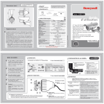
USER INFORMATION
CONTENTS
P/N: 800-11984V1-A 10/2012
CAUTION
Thank you for purchasing this COLOR VIDEO CAMERA.
Before using this camera, please read this operation manual carefully
to obtain the best result and keep this manual for future reference.
RISK OF ELECTRIC SHOCK
DO NOT OPEN
Performance Series
CAUTION ! TO REDUCE THE RISK OF ELECTRIC SHOCK, DO NOT REMOVE COVER (OR BACK).
NO USER-SERVICEABLE PARTS INSIDE. REFER SERVICING TO QUALIFIED SERVICE
PERSONNEL.
WEATHERPROOF IR CAMERA
The lightning flash with arrowhead symbol, within an equilateral triangle, is intended to alert
the user to the presence of un-insulated “dangerous voltage” within the product’s enclosure
that may be of sufficient magnitude to constitute a risk of electric shock to persons.
HB75(X)
The exclamation point within an equilateral triangle is intended to alert the user to the presence
of important operating instructions in the literature accompanying the appliance.
Need Help?
Call 1.800.323.4576 for sales, service and customer support.
www.honeywellvideo.com
www.honeywellvideo.com
WARNING This device is configured for 12 V DC operation only; do NOT connect to higher
voltage. Use only with NRTL approved 12 V DC power supplies. To prevent
potential ground loop issues, a separate PSU should be used for each camera.
A multiple output PSU may be used if the multiple output PSU has isolated and
protected (2A MAX) outputs.
The light emitted from the near-infrared light emitting diodes (LEDs) provides
illumination over a wide area. This light is not considered a risk to the
unshielded human eye. However, as with any light source, it is recommended
that normal precautions be taken to avoid unnecessary exposure. For example,
avoid staring into the beam or viewing directly with optical instruments at close
range.
Information to the User: This equipment has been tested and found to comply with the limits for a
Class A digital device. Pursuant to Part 15 of the FCC Rules, these limits are designed to provide
reasonable protection against harmful interference when the equipment is operated in a commercial
environment. This equipment generates, uses, and can radiate radio frequency energy and, if not
installed and used in accordance with the instruction manual, may cause harmful interference to
radio communications. Operation of this equipment in a residential area is likely to cause harmful
interference in which case the user will be required to correct the interference at his own expense.
10
6. NAME AND FUNCTIONS
11
7. CONNECTIONS
12
8. OPERATING CAMERA
13
9. SPECIFICATION
30
10. TROUBLESHOOTING
32
5
2. PRECAUTIONS
Caution
Do not disassemble the camera.
There are no user repairable parts inside.
Retain Instructions
Changes or modifications not expressly approved by the party responsible for
compliance could void the user’s authority to operate the equipment.
Save these instructions for later use.
Do not drop the camera or subject them to physical shocks.
It can cause malfunctions to occur.
This Class A digital apparatus complies with Canadian ICES-003.
Cet appareil numérique de la Classe A est conforme à la norme NMB-003 du Canada.
Cleaning
Never keep the camera face to strong light directly.
It can damage CCD.
Manufacturer’s Declaration of Conformance
Do not use liquid cleaners or aerosol
cleaners. Use a damp cloth for cleaning.
Do not touch the camera lens, dome or bezel (front glass plate).
It can cause smudging and obstructions in video images.
2
Power source
This product should be operated only from
a 12 V DC power source as indicated on the
marking label.
3
3. FEATURES
Do not install the camera in extreme temperature conditions.
Operate the camera under conditions where temperatures are within +14°F to +122°F (-10°C to +50°C).
Ensure there is enough ventilation in high temperature environments.
Read Instructions
Read all of the safety and operating instructions
before using the product.
The manufacturer declares that the equipment supplied with this guide is compliant with the essential
requirements of the EMC Directive 2004/108/EC and the General Product Safety Directive (GPSD)
2001/95/EC, confirming to the requirements of standards EN 55022 for emissions, EN 50130-4 for
immunity, and EN 60065 for Electrical Equipment safety.
IR LEDs could be warm after prolonged use.
When this camera is installed near wireless communication devices
that emit strong electromagnetic field, irregularity such as noise
on the monitor may appear.
NOTE
6
7
7. CONNECTIONS
4. SUPPLIED ACCESSORIES
Adaptive IR Technology
8. OPERATING CAMERA
ESC
Connecting to Monitor and Power
"Adaptive IR" technology dramatically eliminates the white out effect and saturation on close objects,
producing a clear and recognizable image regardless of viewing condition or location of objects.
LENS
1/3″ High Sensitivity CCD
- 0.3 LUX (COLOR)
- 0 LUX (IR LED ON)
Owner’s Manual
Sunshield
Bracket Mounting Screws
Mount
Sunshield Fastener
NO
Function
Terminal Color
#1
Video Output
Yellow
1.0 Vp.p
#2
Power Input
Red
12 V DC(±10%),
Max 4.8 W / 400 mA
MANUAL
RED
BLUE
0~160
0~160
PUSH
ON
OFF
LEVEL
0~20 (IR MODE:FIXED)
IRED
MODE
CHANGE LEVEL
WIDE, SMART
LOW, MIDDLE, HIGH
BURST
ON/OFF
OFF, LOW, MIDDLE, HIGH
OFF, LOW, MIDDLE, HIGH
0~20
AGC
GND
DAY / NIGHT
User-friendly menus
- High Resolution (600 TVL)
- SBLC (Super Back Light Compensation)
- DNR (Digital Noise Reduction)
- Privacy zone selectable
- Mirror (Horizontal)
- Flickerless On/Off
SHUTTER
COLOR
B/W
SBLC
DNR
SHARPNESS
MIRROR
Remark
IMAGE ADJ
Mounting Screw
DC Plug Cable
L-Wrench
MOTION
Breather vent
8
9
5. INSTALLATION
12
PRIVACY
Sunshield
IMAGE ADJ
1
1 IR LED
850nm / 30°(18EA)
IR Camera
COLOR GAIN
3 Zoom Handle
Used to adjust zoom magnification by
turning.
Bracket
CAM TITLE
2
GENERAL
3
11
LENS DC
1~4
OFF, ON
1~24
8~126 / 10~146
8~126 / 11~149
4~191/ 8~191
4~191 / 9~192
OFF
, ON
13
1/60(50)
EXIT - MENU
DC
ATW
ON
IRED
16
WHITE BAL (White Balance)
AGC (Automatic Gain Control)
Select WHITE BAL using the UP or DOWN button. You can select from ATW, MANUAL,
and PUSH using the LEFT or RIGHT button.
Select AGC using the UP or DOWN button. You can select between OFF, and ON using
the LEFT or RIGHT button.
AGC is fixed at a certain level in IR LED mode.
AGC level is selectable in COLOR, or B/W mode.
1. ATW : Color temperature is automatically adjusted for light sources in the 2,000ºK to 10,000ºK range.
2. MANUAL : To adjust the white balance manually.
- Select MANUAL using the UP or DOWN button and press the MENU button to activate WB MANUAL
option.
1. ON : Select ON using the LEFT or RIGHT button and press the MENU button to activate the AGC
option.
WB MANUAL
AGC
TOP
reduce
RIGHT
extend
RIGHT
1
BOTTOM
5) INITIAL : To reset the MOTION DETECT mode.
- Select INITIAL using the UP or DOWN button. You can reset the MOTION DETECT mode using
the MENU button.
6) RETURN : To return to IMAGE ADJ MENU.
- Select RETURN using the UP or DOWN button. You can return to IMAGE ADJ MENU using
the MENU button.
, ON
,
,
button.
MENU
DOWN : Move down
UP : Move up
LEFT : Move left
RIGHT : Move right
LENS
WHITE BAL
AGC
DAY/NIGHT
IMAGE ADJ
GENERAL
INITIAL
EXIT
DC
ATW
ON
IRED
ON
If the OSD MENU is changed then INITIAL will be OFF
(EXCEPT : LENS).
Select IMAGE ADJ using the UP or DOWN button and press the MENU button to activate
the IMAGE ADJ mode.
IMAGE ADJ
ON
SBLC
DNR
SHARPNESS
MIRROR
MOTION
PRIVACY
COLOR GAIN
INITIAL
RETURN
EXIT - MENU
It is possible to select ON/OFF using
the LEFT or RIGHT button.
OFF
LOW
OFF
ON
IR LED
MODE
WIDE
CHANGE LEVEL
MIDDLE
1. SBLC (Super Back Light Compensation) : To lighten a darker part of the image.
- Select SBLC using the UP or DOWN button. You can select between OFF, LOW, MIDDLE,
and HIGH using the LEFT or RIGHT button.
- SBLC turns to OFF automatically at night.
2. DNR (Digital Noise Reduction) : To reduce the image noise especially during low ambient
lighting conditions.
- Select DNR using the UP or DOWN button. You can adjust between OFF, LOW, MIDDLE, and
HIGH using the LEFT or RIGHT button.
1) AREA : To specify MOTION DETECTION area.
- Select AREA using the UP or DOWN button. You can select from
area position 1 to 4 using the LEFT or RIGHT button.
SHARPNESS
LEVEL
1
2
3
4
21
EXIT - MENU
4. MIRROR :
- Select MIRROR using the UP or DOWN button.
You can select from ON/OFF using the LEFT or
RIGHT button.
(1) ON : Horizontal image flip.
(2) OFF : Default.
2) DISPLAY : To display MOTION DETECTED area on the video.
- Select DISPLAY using the UP or DOWN button. You can select
between ON/OFF using the LEFT or RIGHT button.
(1) ON : Display the MOTION DETECTED area on the screen.
(2) OFF : Disable.
MOTION
1
OFF
5
19
62
13
89
ON
AREA
DISPLAY
SENSITIVITY
TOP
BOTTOM
LEFT
RIGHT
INITIAL
RETURN
1
3) SENSITIVITY : To set up the motion sensitivity.
- Select SENSITIVITY using the UP or DOWN button. You can adjust the motion sensitivity of
a movement from 1 to 24 using the LEFT or RIGHT button.
(1) 1 : Most sensitive (highest).
(2) 24 : Least sensitive (lowest).
2. OFF : Disable the AGC.
19
(1) TOP : Extend or reduce the upper area of the MOTION DETECTED area (8 to 126).
(2) BOTTOM : Extend or reduce the bottom area of the MOTION DETECTED area (8 to 126).
(3) LEFT : Extend or reduce the left side of the MOTION DETECTED area (4 to 191).
(4) RIGHT : Extend or reduce the right side of the MOTION DETECTED area (4 to 191).
, ON
OFF
5. MOTION (Motion Detect) : Display only (No output signal)
- Select MOTION using the UP or DOWN button and
press MENU button to activate the MOTION DETECT
option.
18
4) TOP / BOTTOM / LEFT / RIGHT : Users can specify MOTION DETECTED area.
- Select TOP, BOTTOM, LEFT, or RIGHT using the UP or DOWN button. You can adjust the AREA
using the LEFT or RIGHT button.
OFF
BURST
3. SHARPNESS : To adjust SHARPNESS of the image.
- Select SHARPNESS using the UP or DOWN button.
- Select
and press the MENU button to activate
the SHARPNESS option.
- You can adjust the sharpness from 0 to 20 using the
LEFT or RIGHT button.
1. LEVEL : You can adjust between 0 to 20 using the LEFT or RIGHT button.
3. PUSH : Push Lock mode fixes the white balance based on current lighting. For best results,
place a white surface (such as a piece of paper) in front of the camera during adjustment.
a
b
c
d
Press the joystick in its straight position.
f Sevice Monitor Connecter :
Use service monitor connector to set camera
angle & focus when installing.
20
EXIT - MENU
1. RED : To adjust density of RED (0~160)
2. BLUE : To adjust density of BLUE (0~160)
d
e MENU(SET) :
EXIT - MENU
LEVEL
EXIT - MENU
c
a
COLOR BURST
3. IRED : IR LED control mode.
WIDE : LED control based on full screen exposure.
Some areas may be over exposed.
SMART : LED output is limited to optimized scene exposure.
RED
BLUE
UP
IMAGE ADJ (Image Adjust)
2. B/W : for BLACK and WHITE mode only (NIGHT mode).
- Select B/W using the LEFT or RIGHT button and press
the MENU button to activate COLOR BURST option.
17
Select each sub-menu by using the ,
Press the MENU(SET) button to select.
15
1. COLOR : for color mode only (DAY mode).
1. DC LEVEL (Adjusts brightness of the image.) :
- Select DC LEVEL using the UP or DOWN button. You can adjust between 0 to 20 level using
the LEFT or RIGHT button.
2. FLK (FLICKERLESS) :
- Select FLK using the UP or DOWN button. You can select between ON / OFF using the LEFT or
RIGHT button.
> OFF : You will be allowed to adjust the shutter speed.
3. SHUTTER (Adjusts the shutter speed of the lens.) :
- IR LED Mode : 1/60 (1/50)
- COLOR, B/W Mode :
Select SHUTTER using the UP or DOWN button. You can adjust from 1/60 (1/50), 1/120 (1/100),
1/250,1/500, 1/700, 1/1K, 1/1600, 1/2500, 1/5K, 1/7K, 1/10K, 1/30K, 1/60K, 1/120K(sec) level
using the LEFT or RIGHT button.
ON
b
f
UP/DN, LE/RI
ENG
Select DAY / NIGHT using the UP or DOWN button.
You can select between IRED, COLOR, and B/W
using the LEFT or RIGHT button.
OFF
SHUTTER
MENU
LENS
WHITE BAL
AGC
DAY/NIGHT
IMAGE ADJ
GENERAL
INITIAL
EXIT
OFF
ON
LANGUAGE
VERSION
INITIAL
RETURN
MAIN MENU - GENERAL
Press MENU button to access the SETUP menu.
e
DOWN
0~20
0~20
OFF , ON
DAY / NIGHT
DC LEVEL
FLK
Use the joystick to navigate through the menus.
14
LENS DC
Select DC and press the MENU button to have
LENS DC activated.
Press the MENU button to access the SETUP menu.
1~4
OFF, ON
WHITE, YELLOW, GREEN, BLUE, RED, BLACK, GRAY
4~63 / 6~74
5~64 / 7~75
18~205 / 22~206
19~206 / 23~207
OFF , ON
INITIAL
RETURN
10
LENS
AREA
DISPLAY
COLOR
TOP
BOTTOM
LEFT
RIGHT
INITIAL
RETURN
R-Y
B-Y
INITIAL
RETURN
2 Focus Handle
Used to provide for accurate focusing
of object within the lens field of view.
Mounting screw
24
LEVEL
OFF, ON
AREA
DISPLAY
SENSITIVITY
TOP
BOTTOM
LEFT
RIGHT
INITIAL
RETURN
6. NAME AND FUNCTIONS
Sunshield fastener
1
0~5
0~5
1/60(1/50), 1/120(1/100), 1/250, 1/500, 1/700, 1/1K, 1/1600, 1/2500
1/5K, 1/7K, 1/10K, 1/30K, 1/60K, 1/120K
IR MODE:1/60 (1/50)
ATW
WHITE BAL
- Connect the video-out jack to the video-in jack of monitor.
- Connect the power adapter to the power input connecter.
- Use 12 V DC power source.
- Use the power rated at least 400 mA (12 V DC).
BRIGHTNESS
DC LEVEL
DC
Video Output
For 12 V DC Power Type
Owner’s Manual
Min Illumination (F1.4, 50 IRE, AGC Max)
LEFT
9
5. INSTALLATION
FCC Compliance Statement
Installation and servicing should be performed only by qualified and experienced personnel to
conform to all local codes and to maintain your warranty.
NOTE
8
800-11984V1 - A - 10/2012
1. SAFETY INSTRUCTIONS
Caution
7
3. FEATURES
4
READ AND KEEP THIS OPERATION MANUAL
Warnings and Cautions
6
2. PRECAUTIONS
4. SUPPLIED ACCESSORIES
Operation Manual
Need Help?
Call 1.800.323.4576 for sales, service and customer support.
1. SAFETY INSTRUCTIONS
6. PRIVACY :
- Select PRIVACY using the UP or DOWN button and
press the MENU button to activate the PRIVACY option.
1) AREA : To specify the PRIVACY area.
- Select AREA using the UP or DOWN button. You can
select from area position 1 to 4 using the LEFT or RIGHT
button.
22
2) DISPLAY : To display the Privacy Zone area.
- Select DISPLAY using the UP or DOWN button. You can
select between ON/OFF using the LEFT or RIGHT button.
(1) ON : Display the Privacy Zone area.
(2) OFF : Disable.
GENERAL
Select GENERAL using the UP or DOWN button and
press the MENU button to activate the GENERAL mode.
1
OFF
WHITE
15
31
44
104
ON
1
2
3
4
2. LANGUAGE - English LANGUAGE.
GENERAL
PRIVACY
AREA
DISPLAY
COLOR
TOP
BOTTOM
LEFT
RIGHT
INITIAL
RETURN
23
3. VERSION - Displays the firmware version.
OFF
ENG
CAM TITLE
LANGUAGE
VERSION
INITIAL
RETURN
ON
4. INITIAL : To reset to factory default only on the GENERAL mode.
- Select INITIAL using the UP or DOWN button.
You can reset to factory default for GENERAL mode using the MENU button.
5. RETURN : To return to MENU.
- Select RETURN using the UP or DOWN button. You can return to the MENU using the MENU button.
1. CAM TITLE :
- Select CAM TITLE using the UP or DOWN button.
You can adjust ON/OFF using the LEFT or RIGHT button.
(1) ON : To display the camera title on the screen.
(2) OFF : Disable.
CAM TITLE
UP/DN
LE/RI
-
CHAR SELECT
POSITION
INITIAL
: To reset to factory default.
- Select INITIAL using the UP or DOWN button and reset to factory default using the MENU button.
EXIT - MENU
- Select ON and press the MENU button to display CAM TITLE.
(1) UP/DN : To select character using the UP or DOWN button (0 to 9, A to Z).
(2) LE/RI : To select position using the LEFT or RIGHT button.
3) COLOR : To change the color of the privacy zone.
- Select COLOR using the UP or DOWN button.
You can select from WHITE, YELLOW, GREEN, BLUE, RED,
BLACK, or GRAY using the LEFT or RIGHT button.
25
EXIT
: To exit the OSD setup menu.
- Select EXIT using the UP or DOWN button and close the OSD setup menu by pressing the MENU
button.
29
28
9. SPECIFICATION
4) TOP / BOTTOM / LEFT / RIGHT : Users can specify a PRIVACY ZONE area.
- Select TOP, BOTTOM, LEFT, or RIGHT using the UP or DOWN button. You can adjust the privacy
zone using the LEFT or RIGHT button.
(1) TOP : Extend or reduce the upper area of the PRIVACY area (4 to 63).
(2) BOTTOM : Extend or reduce the bottom area of the PRIVACY area (5 to 64).
(3) LEFT : Extend or reduce the left side of the PRIVACY area (18 to 205).
(4) RIGHT : Extend or reduce the right side of the PRIVACY area (19 to 206).
reduce
TOP
LEFT
1
RIGHT
RIGHT
extend
1
7. COLOR GAIN :
- Select COLOR GAIN using the UP or DOWN button and
then press the MENU button to activate the COLOR MODE
option.
8. INITIAL :
To reset to factory default only on the IMAGE ADJ mode.
- Select INITIAL using the UP or DOWN button and reset the
IMAGE ADJ mode using the MENU button.
COLOR GAIN
R-Y
B-Y
EXIT - MENU
1. R-Y : To adjust density of RED (0~20)
2. B-Y : To adjust density of BLUE (0~20)
9. RETURN :
To return to MAIN MENU.
- Select RETURN using the UP or DOWN button and return
to MENU using the MENU button.
BOTTOM
26
5) INITIAL : To reset to factory default only on the PRIVACY mode.
- Select INITIAL using the UP or DOWN button. You can reset the PRIVACY mode using the MENU
button.
6) RETURN : To return to IMAGE ADJ MENU.
- Select RETURN using the UP or DOWN button. You can return to IMAGE ADJ MENU using the MENU
button.
10. TROUBLESHOOTING
27
MEMO
Nothing appears on the screen
Check that the power cord and the video cable between the camera and monitor are properly connected.
Check that you have properly connected the VIDEO cable to the camera VIDEO output jack.
The image on the screen is dim
If the lens is obstructed (for example, with dirt), clean the lens with a soft, clean cloth.
Set the monitor to proper condition.
If the camera is exposed to too strong light, change the camera position.
Adjust the lens’ focus properly.
The image on the screen is dark
Adjust the contrast feature of the monitor.
If you loop through an intermediate device, set the termination (75 Ohms / Hi-Z) properly.
33
32
34
High resolution
NTSC/PAL
Image Sensor
1/3″ high sensitivity CCD
Effective Pixels (H × V)
768 × 494 (NTSC) / 752 × 582 (PAL)
Video Output
Composite : 1.0 Vp-p, 75 ohms
Sync. System
Internal sync
S/N Ratio
50db or more (sharpness, AGC off)
Horizontal Resolution
600 TV lines
Min Illumination
0.3 lux (color) / 0 lux (IR LED on)
ESC
1/60 – 1/120,000 (NTSC) / 1/50–1/120,000 (PAL)
Manual Shutter
1/ 60 (1/50), 1/120 (1/100), 1/ 250, 1/ 500, 1/ 700, 1/ 1K,
1/ 1.6K, 1/ 2.5K, 1/ 5K, 1/ 7K, 1/ 10K, 1/ 30K, 1/ 60K, 1/ 120K
DNR
If you have trouble operating your camera, refer to the following guidelines. If the guidelines do
not help you to solve the problem, contact an authorized technician.
MEMO
MODEL
Signal System
MEMO
Design and specifications are subject to change without notice.
35
30
Off, Low, Middle, High
White Balance
ATW, Manual, Push
SBLC
Off, Low, Middle, High
AGC
On, Off
Day/Night
Ired, Color, BW
Burst
On, Off
Motion Detection
On, Off (4 programmable zones)
Privacy
On, Off (4 programmable zones)
Mirror
On (horizontal), Off
Sharpness
1 ~ 20
OSD Language
English
Applicable Lens
DC iris lens
Supply Voltage
12 V DC (±10%)
Power Consumption
400 mA / 4.8 W (max)
Operating Temperature
14°F to 122°F (–10°C to 50°C)
Storage Temperature / Humidity
–4°F to 140°F (–20°C to 60°C) / 20% to 90% RH
31