1
Legend™ 4500
Snapshot
LEG-4500
OK on Dimmer
Outdoor OK
Sound Activated
DMX512
Master/Slave
Autoswitching
Transformer
Replaceable Fuse
User Serviceable
Duty Cycle
USER MANUAL
Chauvet, 3000 N 29th Ct, Hollywood, FL 33020 U.S.A.
(800) 762-1084 – (954) 929-1115
FAX (954) 929-5560
www.chauvetlighting.com
TABLE OF CONTENTS
1. Before You Begin ...................................................................................................................................... 3
What is included.............................................................................................................................................. 3
Unpacking Instructions .................................................................................................................................... 3
Safety Instructions .......................................................................................................................................... 3
LED Expected Lifespan .................................................................................................................................. 3
2. Introduction ............................................................................................................................................... 4
Features .......................................................................................................................................................... 4
DMX Channel Summary ................................................................................................................................. 5
Product Overview ............................................................................................................................................ 6
3. SETUP ........................................................................................................................................................ 8
AC Power ........................................................................................................................................................ 8
Fuse Replacement .......................................................................................................................................... 8
Mounting ......................................................................................................................................................... 9
Orientation ...................................................................................................................................................... 9
Rigging ............................................................................................................................................................ 9
Lens Assembly Installation/Replacement ......................................................................................................10
Fixture Linking................................................................................................................................................11
Data Cabling ..................................................................................................................................................11
DMX Data Cable ............................................................................................................................................ 11
Cable Connectors .......................................................................................................................................... 11
3-Pin to 5-Pin Conversion Chart .................................................................................................................... 12
Setting up a DMX Serial Data Link.................................................................................................................12
Master/Slave Fixture Linking ..........................................................................................................................12
4. Operating Instructions.............................................................................................................................13
Control Options ..............................................................................................................................................13
DMX-512 control ............................................................................................................................................13
Setting the DMX address ...............................................................................................................................14
Control Panel Functions .................................................................................................................................14
Menu Map ......................................................................................................................................................15
DMX512 Channel Values ...............................................................................................................................16
5. Appendix...................................................................................................................................................18
DMX Primer ...................................................................................................................................................18
General Maintenance .....................................................................................................................................19
Returns Procedure .........................................................................................................................................19
Claims ............................................................................................................................................................19
Photometrics ..................................................................................................................................................20
DMX Channels Chart .....................................................................................................................................21
Legend ™4500 Service Maintenance Guide..................................................................................................24
Blow-out Diagram. .........................................................................................................................................23
Technical Specifications ................................................................................................................................24
Legend™ 4500 User Manual
2
12/10/2008 4:28 PM
1. BEFORE YOU BEGIN
What is included
1 x Legend™ 4500
1 x Mounting Bracket kit w/screws
1 x Neutrik® Power cable with plug
1 x Warranty Card
1 x User Manual
Unpacking Instructions
Immediately upon receiving a fixture, carefully unpack the carton, check the contents to ensure
that all parts are present, and have been received in good condition. Notify the shipper
immediately and retain packing material for inspection if any parts appear damaged from
shipping or the carton itself shows signs of mishandling. Save the carton and all packing
materials. In the event that a fixture must be returned to the factory, it is important that the fixture
be returned in the original factory box and packing.
Safety Instructions
Please read these instructions carefully, which includes important
information about the installation, usage and maintenance of this
product.
Please keep this User Guide for future consultation. If you sell the unit to another user, be sure
that they also receive this instruction booklet.
Always make sure that you are connecting to the proper voltage, and that the line voltage you
are connecting to is not higher than that stated on the decal or rear panel of the fixture.
The unit must be installed in a location with adequate ventilation, at least 20in (50cm) from
adjacent surfaces. Be sure that no ventilation slots are blocked.
Always disconnect from power source before servicing or replacing lamp or fuse and be sure to
replace with same lamp source.
Secure fixture to fastening device using a safety chain. Never carry the fixture solely by its head.
Use its carrying handles.
Maximum ambient temperature (Ta) is 104°F (40°C). Do not operate fixture at temperatures
higher than this.
In the event of a serious operating problem, stop using the unit immediately. Never try to repair
the unit by yourself. Repairs carried out by unskilled people can lead to damage or malfunction.
Please contact the nearest authorized technical assistance center. Always use the same type
spare parts.
Caution!
Caution!
There are no user serviceable parts inside the unit. Do not open the housing or
attempt any repairs yourself. In the unlikely event your unit may require
service, please contact CHAUVET at: 954-929-1115.
After prolonged periods of operation, the fixture chassis may reach high
temperatures. Use caution when handling this fixture.
LED Expected Lifespan
LEDs gradually decline in brightness over time. HEAT is the dominant factor that leads to the
acceleration of this decline. Packaged in clusters, LEDs exhibit higher operating temperatures
than in ideal or singular optimum conditions. For this reason when all color LEDs are used at
their fullest intensity, life of the LEDs is significantly reduced. It is estimated that a viable lifespan
of 40,000 to 50,000 hours will be achieved under normal operational conditions. If improving on
this lifespan expectancy is of a higher priority, place care in providing for lower operational
temperatures. This may include climatic-environmental and the reduction of overall projection
intensity
Legend™ 4500 User Manual
3
12/10/2008 4:28 PM
2. INTRODUCTION
Features
10 or 14-channel DMX-512 LED moving yoke color wash
Pan: 540º / tilt: 270º
RGBW color mixing with or without DMX controller
Variable electronic strobe
Variable electronic dimmer (0 – 100%)
Remote fixture reset and vector speed channel
255 user-programmable steps without DMX controller
Color temperature presets (3,200ºK - 10,000ºK) or create your own
Adjustable fan speed
ADDITIONAL FEATURES
High-powered, 2W – 3W (720mA – 1000mA) LEDs
3-pin and 5-pin DMX connections
Neutrik PowerCon® connector
User-selectable pan/tilt ranges
Automatic pan/tilt correction
Reset to factory settings option
User-selectable basic or advanced operating modes
LCD display with password protection
OPTIONS
Optical systems available:, 15 (installed), 30 (LLENS3054)
Legend™ 4500 User Manual
4
12/10/2008 4:28 PM
DMX Channel Summary
The Legend™ 4500 has 2 DMX channel configurations, referred to as “Personalities” in this manual and in the fixture
control board. The 2 personalities are [Advanced, Basic]. Each of the personalities can be accessed from the control
panel. Please see section on “Control Panel Functions” on a description on how to accomplish this.
[ADVANCED]
[BASIC]
Legend™ 4500 User Manual
CHANNEL DESCRIPTION
1
Pan
2
Pan Fine
3
Tilt
4
Tilt Fine
5
Pan/Tilt Speed
6
Red
7
Green
8
Blue
9
White
10
Color/White Macro
11
Dimmer
12
Strobe
13
14
Dimmer Speed
Control
CHANNEL DESCRIPTION
1
Pan
2
Tilt
3
Red
4
Green
5
Blue
6
White
7
Color/White Macro
8
Dimmer
9
10
Strobe
Control
5
12/10/2008 4:28 PM
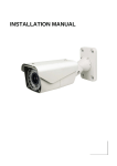
Product Overview
Neutrik® Power Input
Power switch
Fuse holder
DMX Input
5-pin
DMX Output
5-pin
DMX Input
3-pin
DMX Output
3-pin
Control board
Legend™ 4500 User Manual
6
12/10/2008 4:28 PM
Product Dimensions
Legend™ 4500 User Manual
7
12/10/2008 4:28 PM
3. SETUP
AC Power
This fixture has an auto-switching switch-mode power supply that can accommodate a wide
range of input voltages. The only thing necessary to do before powering on the unit is to make
sure the line voltage you are applying is within the range of accepted voltages. This fixture will
accommodate between 100V and 240V AC 50-60 Hz. All fixtures must be powered directly off a
switched circuit and cannot be run off a rheostat (variable resistor) or dimmer circuit, even if the
rheostat or dimmer channel is used solely for a 0% to 100% switch.
Each fixture ships with Neutrik® power input cables. Each fixture ships with a power adapter to
male Edison connector.
Warning!
All fixtures must be connected to circuits with a suitable Earth Ground.
Depending on the application, the lighting fixture may require a different connector Please refer
to the below wire color code if installing a new connector.
Wire
Connection
Connection
Pin
Brown
Blue
Green/Yellow
AC Live
AC Neutral
AC Ground
AC Live
AC Neutral
Ground(Earth)
1
2
3
Disconnect the power cord before replacing a fuse and always
replace with the same type fuse.
Fuse Replacement
With a flat-head screwdriver, unscrew the fuse holder from its housing. Remove the damaged
fuse from its holder and replace with exact same type fuse. Screw the fuse holder back in its
place and reconnect power.
The fuse is located inside
this compartment.
Remove using a flat-head
screwdriver.
Legend™ 4500 User Manual
8
12/10/2008 4:28 PM
Mounting
Orientation
This fixture may be mounted vertically or horizontally.
Rigging
The fixture includes a mounting yoke to which a rigging clamp can be attached.
You must supply your own clamp and make sure the clamp is capable of
supporting the weight of this fixture. It is recommended to use at least 2
mounting points per fixture. You can order “C” and “O”-clamps from any
CHAUVET dealer or distributor (CLP-15, CLP-06 recommended).
If hanging the fixture for over head use, then please follow the below steps.
1.
Block access below the work area and use suitable and stable platform
when installing or servicing fixture.
2.
Safety cables must always be used, secured through the safety cable
passageway. The safety cable must be capable of holding 10 times the
weight of the fixture.
3.
Caution!
Verify the structure can hold 10 times the weight of all to-be installed
fixtures.
This fixture must be mounted in a ventilated location, as it is fan/convection
cooled.
Hanging Clamp
Note!
Clamp is sold separately.
Safety cable
Legend™ 4500 User Manual
9
12/10/2008 4:28 PM
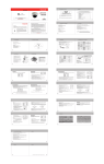
Lens Assembly Installation/Replacement
The Legend™ 4500 comes with 15 lens assembly pre-installed from the factory. However, there is another
optional lens assembly (LLENS3054) available as an accessory, which will alter the beam angle. Please follow
the below instructions for proper replacement/installation.
2. Lens
assembly
3. LED PCB
1. Front plastic cover
1.
Remove the front plastic rim cover (black), by removing the screws that hold it in place.
There are 8 screws to remove for this step.
2.
After removing the front rim cover, remove the screws that hold the lens assembly in place.
Note: use care when performing this procedure, as this gives you direct access
to the LEDs, which are very fragile.
3.
Warning!
You now should have full access to the lens assembly. This must be removed and the old
lenses must be replaced with the new lenses. The same assembly is to be reinstalled with
the new lenses in place and the process is complete.
1. When replacing the lens assembly, please make sure that the power is
disconnected from the fixture beforehand.
2. You must also be VERY CAREFUL when opening this fixture. Improper
handling of this unit may void the warranty if any parts are damaged due to
negligence on behalf of the user.
Legend™ 4500 User Manual
10
12/10/2008 4:28 PM
Fixture Linking
You will need a serial data link to run light shows of one or more fixtures using a DMX-512
controller or to run synchronized shows on two or more fixtures set to a master/slave operating
mode. The combined number of channels required by all the fixtures on a serial data link
determines the number of fixtures the data link can support.
Important: Fixtures on a serial data link must be daisy chained in one single line. To comply with the
EIA-485 standard no more than 32 devices should be connected on one data link.
Connecting more than 32 fixtures on one serial data link without the use of a DMX
optically-isolated splitter may result in deterioration of the digital DMX signal.
Maximum recommended serial data link distance: 500 meters (1640 ft.)
Maximum recommended number of fixtures on a serial data link: 32 fixtures
Data Cabling
To link fixtures together you must obtain data cables. You can purchase CHAUVET-certified
DMX cables directly from a dealer/distributor or construct your own cable. If you choose to create
your own cable please use data-grade cables that can carry a high quality signal and are less
prone to electromagnetic interference.
DMX D ATA C ABLE
Use a Belden© 9841 or equivalent cable which meets the specifications for EIA RS-485
applications. Standard microphone cables cannot transmit DMX data reliably over long
distances. The cable will have the following characteristics:
2-conductor twisted pair plus a shield
Maximum capacitance between conductors – 30 pF/ft.
Maximum capacitance between conductor and shield – 55 pF/ft.
Maximum resistance of 20 ohms / 1000 ft.
Nominal impedance 100 – 140 ohms
C ABLE CONNECTORS
Cabling must have a male XLR connector on one end and a female XLR connector on the other
end.
1
3
2
3-pin DMX connector configuration
COMMON
INPUT
1
3
2
1
3
2
DMX +
DMX
-
5-pin DMX connector configuration
Resistance 120
ohm 1/4w
between pin 2
(DMX -) and pin
3 (DMX +) of the
last fixture.
OUTPUT
Resistance 120
ohm 1/4w
between pin 2
(DMX -) and pin
3 (DMX +) of the
last fixture.
Termination reduces signal errors.
To avoid signal transmission
problems and interference, it is
always advisable to connect a DMX
signal terminator.
CAUTION Do not allow contact between the common and the fixture’s chassis ground. Grounding
the common can cause a ground loop, and your fixture may perform erratically. Test
cables with an ohm meter to verify correct polarity and to make sure the pins are not
grounded or shorted to the shield or each other.
Legend™ 4500 User Manual
11
12/10/2008 4:28 PM
3-PIN TO 5-PI N CO NVERSION CH AR T
Note!
If you use a controller with a 5 pin DMX output connector, you will need to use a 5 pin to 3
pin adapter. CHAUVET Model No: DMX5M, or DMX5F.
The chart below details a proper cable conversion:
3 PIN TO 5 PIN CONVERSION CHART
Conductor
3 Pin Female (output)
5 Pin Male (Input)
Ground/Shield
Pin 1
Pin 1
Data ( - ) signal
Pin 2
Pin 2
Data ( + ) signal
Pin 3
Pin 3
Do not use
Do not use
Do not use
Do not use
Setting up a DMX Serial Data Link
Universal DMX Controller
1. Connect the (male) 3 pin connector side of
the DMX cable to the output (female) 3 pin
connector of the controller.
2. Connect the end of the cable coming from
the controller which will have a (female) 3
pin connector to the input connector of the
next fixture consisting of a (male) 3 pin
connector.
This drawing provides a
general illustration of the
DMX Input/Output panel of
a lighting fixture.
3. Then, proceed to connect from the output
as stated above to the input of the following
fixture and so on.
CHAUVET Certified DMX Data Cables
Order Code
Description
DMX1.5
DMX Cable 1.5m/4.9ft
DMX4.5
DMX Cable 4.5m/14.8ft
DMX10
DMX Cable 10m/32.8ft
Continue the link
Master/Slave Fixture Linking
1. Connect the (male) 3 pin connector side of the DMX cable to the output (female) 3 pin
connector of the first fixture.
2. Connect the end of the cable coming from the first fixture which will have a (female) 3 pin
connector to the input connector of the next fixture consisting of a (male) 3 pin connector.
Then, proceed to connect from the output as stated above to the input of the following fixture
and so on.
Often, the setup for Master-Slave
and Standalone operation requires
that the first fixture in the chain be
initialized for this purpose via either
settings in the control panel or DIPswitches. Secondarily, the fixtures
that follow may also require a slave
setting. Please consult the
“Operating Instructions” section in
this manual for complete instructions
for this type of setup and
configuration.
Legend™ 4500 User Manual
Slave
Slave
12
Master
12/10/2008 4:28 PM
4. OPERATING INSTRUCTIONS
Control Options
The Legend™ 4500 is addressable in the DMX range of 001 to 512. In its simplest control form,
this allows for the control of up to 36 fixtures in the 14-channel Advanced personality.
DMX-512 control
The Legend™ 4500 operates on 14 channels of DMX (“Advanced” personality). Address each
fixture in increments of 14 channels. (I.e. 1,15,29,43, etc…) To save time you can use the same
DMX address for each fixture. All fixtures will then respond simultaneously to control. You may
also group your fixtures and address those groups alike for faster programming and control.
1. Access the control panel function by pressing the (MENU) button until the {1.4 OPERATION}
is displayed.
2. Press (ENTER) and use the (UP/DOWN) buttons to select {DMX} function. Press (ENTER).
3. Then, Press (MENU) button and use the (UP/DOWN) buttons until {ADDRESS} is displayed.
4. Pres the (ENTER) button.
6. Use the (UP/DOWN) buttons to increase or decrease channels between 001 and 512.
7. Press the (ENTER) button to confirm action. Then press (MENU) to exit.
Legend™ 4500 User Manual
13
12/10/2008 4:28 PM
Setting the DMX address
Each fixture requires a "start address" from 1 to 512. A fixture requiring one or more channels
for control begins to read the data on the channel indicated by the start address. For example,
a fixture that occupies or uses 7 channels of DMX and was addressed to start on DMX channel
100, would read data from channels: 100, 101, 102, 103, 104, 105 and 106. Choose start
addresses so that the channels used do not overlap and note the start address selected for
future reference. The Legend™ 4500 uses up to 9 channels of DMX. If this is your first time
using DMX, we recommend reading the DMX Primer in the Appendix Section.
Control Panel Functions
All fixture functions and settings are accessible via the built-in control panel interface.
MENU
ENTER
DOWN
UP
BUTTON
FUNCTION
MENU
Exits from the current menu or function
ENTER
Enables the currently displayed menu or sets the currently selected value in to
the selected function
Navigates upwards through the menu list and increases the numeric value
when in a function
Navigates downwards through the menu list and decreases the numeric value
when in a function
DOWN
UP
Legend™ 4500 User Manual
14
12/10/2008 4:28 PM
Menu Map
MAIN FUNCTION
1. Intro
2. Invert
3. Range
4. Special
5. Edit
6. Extra
SUB-FUNCTION
SELECTION
INSTRUCTION
1.1 Address
1.2 Reset
000 ~ 255
Yes ~ No
Sets the DMX starting address
1.3 Fans
High, Normal, Low, Auto
Sets the fan speed
1.4 Operation
DMX512
Auto1
Auto2
Custom
Slave
Test
Use with DMX controller
Built-in Program 1
Built-in Program 2
Custom Internal Program
Use for Master/Slave
Use for testing functions
1.5 Channels
Basic ~ Advanced
Choose between 10 or 14-channels
1.6 Display
60 close ~ Bright
Choose display readout option
1.7 Info
Edition
Displays the version number
2.1 Pan
Normal ~ Reverse
Invert Pan movement
2.2 Tilt
Normal ~ Reverse
Invert Tilt movement
2.2 Dimmer
Normal ~ Reverse
Invert dimmer
2.4 Use
No ~ Yes
Turns on/Off this invert function
3.1 P/start
000 ~ 255
Sets the Pan starting position
3.2 P/Finish
000 ~ 255
Sets the Pan finishing position
3.3 T/start
000 ~ 255
Sets the Tilt starting position
3.4 T/Finish
000 ~ 255
Sets the Tilt finishing position
3.5 Use
No ~ Yes
Turns on/off this range function
4.1 Black Delay
No ~ Yes
This will enable/disable the need to
wait 3 seconds for turning on/off the
pan/tilt black function.
4.2 Reset
DMX ~ System
Enables/disables DMX control of
RESET function
4.3 Dimmer
Normal ~ System
Sets the dimmer to normal (linear) or
special dimming curve
4.4 RGB
No ~ Yes
Sets the RGB to full form RGB-towhite (yes) or RGB to full intensity
(no)
4.5 Fan
DMX ~ System
5.1 Scene
5.2 Pan
5.3 Tilt
5.4 Speed
5.5 Red
5.6 Green
5.7 Blue
5.8 White
5.9 Strobe
5.10 Dimmer
5.11 Time
5.12 Use
6.1 User key
6.2 password
000-~ 255
000 ~ 255
000 ~ 255
000 ~ 255
000 ~ 255
000 ~ 255
000 ~ 255
000 ~ 255
000 ~ 255
000 ~ 255
000 ~ 255
No ~ Yes
0000
1111
Legend™ 4500 User Manual
Resets fixture when selecting Yes
Enables/disables DMX control of fan
speed
Chooses the step to edit
Sets the pan location for the step
Sets the tilt location for the step
Chooses speed for the current step
Combine these channels to create the
desired color mixture
Strobes from 0-20Hz
Chooses dimmer for current step
Chooses time for the current step
Select yes to run the user program
Modifies the User key
Modifies the password
15
12/10/2008 4:28 PM
DMX512 Channel Values
The Legend™ 4500 has 2 DMX512 channel configurations [ADVANCED, BASIC].
BASIC
CHANNEL
VALUE
FUNCTION
1
000 255
Pan
Clockwise rotate 0 ~540
2
000 255
Tilt
Tilt from 0 ~270
3
000 255
Red
0 100%
4
000 255
Green
0 100%
5
000 255
Blue
0 100%
6
000 255
7
000 005
006 025
026 045
046 065
066 085
086 105
106 125
126 145
146 165
166 180
181 190
191 200
201 205
206 210
211 215
216 220
221 225
226 230
231 235
236 240
241 245
246 250
251 255
8
000 255
9
000 255
10
000 019
020 039
040 059
060 079
080 099
100 119
120 139
140 149
150 159
160 169
170 179
180 189
190 199
200 219
220 255
Legend™ 4500 User Manual
White
0 100%
Color/White Macro
No Function
Red Down/Green down/Blue 100%
Red 100%/Green up/Blue down
Red 100%/Green 0%/Blue 100%
Red up/Green 0%/Blue 100%
Red 0%/Green Down/Blue 100%
Red 0%/Green 100%/Blue Up
Red Down/Green 100%/Blue 0%
Red 100%/Green up/Blue 0%
No Function
No Function
Red 100%/Green 100%/Blue 100%
White 1:3200K
White 2:3400K
White 3:4200K
White 4:4900K
White 5:5600K
White 6:5900K
White 7:6500K
White 8:7200K
White 9:8000K
White 10:9500K
White 11:10000K
Dimmer
0 100%
Strobe
0 100%
Control
No Function
Pan/tilt black open
Pan/tilt black close
No Function
Fan slow
Fan normal
Fan fast
No Function
Auto 1 (activated after 3 secs)
Auto 2 (activated after 3 secs)
Test (activated after 3 secs)
Custom (activated after 3 secs)
No function
Reset (activated after 3 secs)
No Function
16
12/10/2008 4:28 PM
ADVANCED
CHANNEL
VALUE
FUNCTION
1
000 255
Pan
Clockwise rotate 0 ~540
2
000 255
Pan fine
Fine control of pan movement 0 ~3
3
000 255
Tilt
Tilt from 0 ~270
4
000 255
Tilt fine
Fine control of tilt movement 0 ~3
5
000 255
Pan/Tilt Speed
From fast to slow
6
000 255
Red
0 100%
7
000 255
Green
0 100%
8
000 255
Blue
0 100%
9
000 255
10
000 005
006 025
026 045
046 065
066 085
086 105
106 125
126 145
146 165
166 180
181 190
191 200
201 205
206 210
211 215
216 220
221 225
226 230
231 235
236 240
241 245
246 250
251 255
11
000 255
12
000 255
13
14
000 005
006 255
000 019
020 039
040 059
060 079
080 099
100 119
120 139
140 149
150 159
160 169
170 179
180 189
190 199
200 219
220 255
Legend™ 4500 User Manual
White
0 100%
Color/White Macro
No Function
Red Down/Green down/Blue 100%
Red 100%/Green up/Blue down
Red 100%/Green 0%/Blue 100%
Red up/Green 0%/Blue 100%
Red 0%/Green Down/Blue 100%
Red 0%/Green 100%/Blue Up
Red Down/Green 100%/Blue 0%
Red 100%/Green up/Blue 0%
No Function
No Function
Red 100%/Green 100%/Blue 100%
White 1:3200K
White 2:3400K
White 3:4200K
White 4:4900K
White 5:5600K
White 6:5900K
White 7:6500K
White 8:7200K
White 9:8000K
White 10:9500K
White 11:10000K
Dimmer
0 100%
Strobe
0 100%
Dimmer Speed
No Function
Slow>Fast
Control
No Function
Pan/tilt black activated
Pan/tilt black deactivated
No Function
Fan slow
Fan normal
Fan fast
No Function
Auto 1 (activated after 3 secs)
Auto 2 (activated after 3 secs)
Test (activated after 3 secs)
Custom (activated after 3 secs)
No function
Reset (activated after 3 secs)
No Function
17
12/10/2008 4:28 PM
5. APPENDIX
DMX Primer
There are 512 channels in a DMX-512 connection. Channels may be assigned in any manner.
A fixture capable of receiving DMX 512 will require one or a number of sequential channels.
The user must assign a starting address on the fixture that indicates the first channel reserved
in the controller. There are many different types of DMX controllable fixtures and they all may
vary in the total number of channels required. Choosing a start address should be planned in
advance. Channels should never overlap. If they do, this will result in erratic operation of the
fixtures whose starting address is set incorrectly. You can however, control multiple fixtures of
the same type using the same starting address as long as the intended result is that of unison
movement or operation. In other words, the fixtures will be slaved together and all respond
exactly the same.
DMX fixtures are designed to receive data through a serial Daisy Chain. A Daisy Chain
connection is where the DATA OUT of one fixture connects to the DATA IN of the next fixture.
The order in which the fixtures are connected is not important and has no effect on how a
controller communicates to each fixture. Use an order that provides for the easiest and most
direct cabling. Connect fixtures using shielded two conductor twisted pair cable with three pin
XLR male to female connectors. The shield connection is pin 1, while pin 2 is Data Negative (S) and pin 3 is Data positive (S+). CHAUVET carries 3-pin XLR DMX compliant cables, DMX-10
(33’), DMX-4.5 (15’) and DMX-1.5 (5’)
Legend™ 4500 User Manual
18
12/10/2008 4:28 PM
General Maintenance
To maintain optimum performance and minimize wear fixtures should be cleaned frequently.
Usage and environment are contributing factors in determining frequency. As a general rule,
fixtures should be cleaned at least twice a month. Dust build up reduces light output
performance and can cause overheating. This can lead to reduced lamp life and increased
mechanical wear. Be sure to power off fixture before conducting maintenance.
Unplug fixture from power. Use a vacuum or air compressor and a soft brush to remove dust
collected on external vents and internal components. Clean all glass when the fixture is cold
with a mild solution of glass cleaner or Isopropyl Alcohol and a soft lint free cotton cloth or lens
tissue. Apply solution to the cloth or tissue and drag dirt and grime to the outside of the lens.
Gently polish optical surfaces until they are free of haze and lint.
The cleaning of internal and external optical lenses and/or mirrors must be carried out
periodically to optimize light output. Cleaning frequency depends on the environment in which
the fixture operates: damp, smoky or particularly dirty surrounding can cause greater
accumulation of dirt on the unit’s optics. Clean with soft cloth using normal glass cleaning fluid. Always dry the parts carefully. - Clean the external optics at least every 20 days. Clean the
internal optics at least every 30/60 days.
Returns Procedure
Returned merchandise must be sent prepaid and in the original packing, call tags will not be
issued. Package must be clearly labeled with a Return Merchandise Authorization Number
(RMA #). Products returned without a RMA # will be refused. Call CHAUVET and request a
RMA # prior to shipping the fixture. Be prepared to provide the model number, serial number
and a brief description of the cause for the return. Be sure to properly pack fixture, any shipping
damage resulting from inadequate packaging is the customer’s responsibility. CHAUVET
reserves the right to use its own discretion to repair or replace product(s). As a suggestion,
proper UPS packing or double-boxing is always a safe method to use.
Note:
If you are given a RMA #, please include the following information on a piece of
paper inside the box:
1)
Your name
2)
Your address
3)
Your phone number
4)
The RMA #
5)
A brief description of the symptoms
Claims
Damage incurred in shipping is the responsibility of the shipper; therefore the damage must be
reported to the carrier upon receipt of merchandise. It is the customer's responsibility to notify
and submit claims with the shipper in the event that a fixture is damaged due to shipping. Any
other claim for items such as missing component/part, damage not related to shipping, and
concealed damage, must be made within seven (7) days of receiving merchandise.
Legend™ 4500 User Manual
19
12/10/2008 4:28 PM
Photometrics
Legend™ 4500 User Manual
20
12/10/2008 4:28 PM
Legend™ 4500 User Manual
21
12/10/2008 4:28 PM
DMX Channels Chart
Legend™ 4500 User Manual
22
12/10/2008 4:28 PM
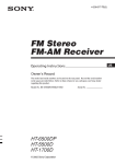
Blow-out Diagram.
16
19
4
10
3
14
13
8
11
9
12
2
1
7
5
Description
Part Number
1 Display/Master PCB
P172-6500DP
2 X/Y PCB
P170-4500XY
3 LED Driver PCB
P175-4500DVR
4 LED metal-core PCB
P222-4500LED
5 Electronic Transformer
P140-4500ELTR
6 Mounting bracket set (not shown)
P111-60BRKT
7
Pan stepper motor
P176-4500PS
8 Tilt stepper motor
P176-4500TS
9 Pan belt
P111-4500PB
10 Tilt belt
P111-4500TB
11 Pan optical sensor (not shown)
P172-6500POS
12 Pan stopper sensor (not shown)
P172-6500PSS
13 Tilt optical sensor (not shown)
P172-6500TOS
14 Tilt stopper sensor (not shown)
P172-6500TSS
15 Arm plastic cover
P112-4500ARM
16 Fan 120mm 24V
P130-24V120M
17 Fan 60mm 24V
P130-24V60MM
18 Power input cable: Neutrik to Edison
P111-80IPWR
19 30 Lens assembly
LLENS3054
Legend™ 4500 User Manual
23
12/10/2008 4:28 PM
Legend ™4500 Service Maintenance Guide
Symptom(s)
Possible Solution(s)
1 or more LED’s are not
illuminating
1 or more LED’s are producing
very low output
Breaker/Fuse keeps blowing
Device has no power
Fixture is not responding to DMX
Clean the fixture regularly to avoid any such failure. This fixture is convection
cooled, which means that if the surface is kept clean and free of debris, then
proper cooling will be allowed to occur
An LED may have failed, resulting in an open circuit. In this event, all of the
red, green, or blue in a single module will no longer illuminate. This does not
mean that all of the LEDs have failed, but the circuit is wired in series.
An LED may have failed, resulting in a short circuit. In this event, only the
single LED which has failed will no longer function. This does not mean that all
of the LEDs have failed, but the circuit is wired in series.
-Note: In the event of LED failure, a replacement LED PCB assembly may be
purchased directly from Chauvet
Part#: P222-4500LED
Check that the lens assembly is installed properly. If the lens assembly is not
aligned properly over the LEDs, then they will not project fully
-See section on Lens Assembly Installation
-Note: In the event of LED failure, a replacement LED PCB assembly may be
purchased directly from Chauvet
Part#: P222-4500LED
Check total load placed on the electrical circuit
Check for a short in the electrical wiring: internal and/or external
Check device’s fuse (internal)
Check for power on Mains
Check cable connections The Legend™ 4500 IP-66 cables must be firmly
connected and locked in place for operation
-Note: In the event of autoswitching transformer failure, the unit can be sent in
for repair; however, a replacement part can be ordered directly from Chauvet
Part#: P140-4500ELTR
Check Control Panel settings for correct addressing
Check DMX cables
Check polarity switch settings on the controller
Check cable connections
Call service technician
-Note: In the event of Display/Master PCB failure, a replacement PCB can be
ordered directly from Chauvet
Part#: P172-4500DP
Use only DMX cables
Loss of signal
Install terminator
Note: Keep DMX cables separated from power cables or black lights
Pan/tilt movement/reset problem
The display backlight will not turn
off and stays lit
1 or more sensors may need to be replaced. This may be either the optical
sensor or the magnetic stopper sensor.
Note In the event of a sensor failure, a replacement sensor may be ordered
directly from Chauvet:
Part#: Magnetic Pan: P172-6500PSS
Optical Pan: P172-6500POS
Magnetic Tilt: P172-6500TSS
Optical Tilt: P172-6500TOS
1 or more sensors may need to be adjusted. This should be done by a
qualified technician, as it involves opening the case of the fixture and
modifying internal components.
There is an option in the control board that determines if the display turns off
after 60 seconds of inactivity, or if the display stays lit indefinitely.
-See section 1.6 in the onboard display “close”.
If you still have a problem after trying the above solutions, please contact CHAUVET
Technical Support at the location on the following page.
Legend™ 4500 User Manual
24
12/10/2008 4:28 PM
Contact Us
World Wide
General Information
CHAUVET
3000 North 29th Court
Hollywood, FL 33020
voice: 954.929.1115
fax: 954.929.5560
toll free: 800.762.1084
Technical Support
CHAUVET
3000 North 29th Court
Hollywood, FL 33020
voice: 954.929.1115 (Press 4)
fax: 954.929.5560 (Attention: Service)
World Wide Web www.chauvetlighting.com
Legend™ 4500 User Manual
25
12/10/2008 4:28 PM
Technical Specifications
WEIGHT & DIMENSIONS
Length ................................................................................................................................. 15.3 in (389 mm)
Width................................................................................................................................... 12.6 in (320 mm)
Height ................................................................................................................................. 15.2 in (385 mm)
Weight ................................................................................................................................... 37 lbs (16.8 kg)
POWER
AC Power Auto-switching ........................................................................................ 100V~240V 50/60Hz AC
Power Consumption ..................................................................................... 280W (2.3A) max at 120V 60Hz
Inrush Current ................................................................................................................ (2.5A) at 120V 60Hz
Power Factor .................................................................................................................... 1.00 at 120V 60Hz
LIGHT SOURCE
Quantity.......54 (14 720mA Red, 13 1000mA Green, 14 1000mA Blue, 12 1000mA White) LED 50,000 hours
PHOTO OPTIC (WITH 15° LENSES)
Luminance @1m ...................................................................................................................... 20,200 @ 2m
Beam Angle.............................................................................................................................................. 10
Field Angle ............................................................................................................................................... 22
COOLING
Fan cooled .............................................................................................................................. 24V 90MM fan
Fan cooled ............................................................................................................................ 24V 120MM fan
CONTROL & PROGRAMMING
Data input ........................................................................................................locking 3-pin XLR male socket
Data input ........................................................................................................locking 5-pin XLR male socket
Data output................................................................................................... locking 3-pin XLR female socket
Data output................................................................................................... locking 5-pin XLR female socket
Data pin configuration (3-pin) ........................................................................... pin 1 shield, pin 2 (-), pin 3 (+)
Data pin configuration (5-pin) ............................ pin 1 shield, pin 2 (-), pin 3 (+), pin 4 (not used), 5 (not used)
Protocols ..............................................................................................................................DMX-512 USITT
DMX Channels ................................................................................................... User Configurable: 10, or 14
STANDARD ORDERING INFORMATION
Legend ™ 4500 ...............................................................................................................................LEG4500
30 Optical Lens Assembly ........................................................................................................... LLENS3054
SPARE PARTS ORDERING INFORMATION
Display/Master PCB (Part) ....................................................................................................... P172-4500DP
X/Y PCB (Part) .........................................................................................................................P170-4500XY
LED Driver PCB (Part) ........................................................................................................... P175-4500DVR
LED Metal-Core PCB: assembled (Part) ................................................................................ P222-4500LED
Electronic Transformer (Part) ............................................................................................... P140-4500ELTR
Mounting bracket (Part) ........................................................................................................... P111-60BRKT
Pan stepper motor (Part) ..........................................................................................................P176-4500PS
Tilt stepper motor (Part) ............................................................................................................ P176-4500TS
Pan belt (Part) ..........................................................................................................................P111-4500PB
Tilt belt (Part) ............................................................................................................................P111-4500PB
Pan optical sensor (Part) ....................................................................................................... P172-6500POS
Pan stopper sensor (Part) ...................................................................................................... P172-6500PSS
Tilt optical sensor (Part) ......................................................................................................... P172-6500TOS
Tilt stopper sensor (Part) ....................................................................................................... P172-6500TSS
Arm plastic cover (Part) ........................................................................................................ P112-6500ARM
Fan 120mm 24V (Part) .......................................................................................................... P130-24V120M
Fan 60mm 24V (Part) ........................................................................................................... P130-24V60MM
Power input cable: Neutrik to Edison (Part) .................................................................... P111-80IPWR
WARRANTY INFORMATION
Warranty .................................................................................................................... 2-year limited warranty
Legend™ 4500 User Manual
26
12/10/2008 4:28 PM