1
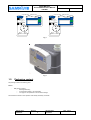
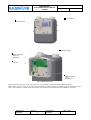
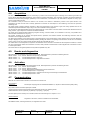
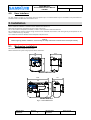
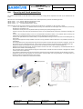
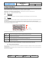
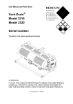
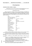
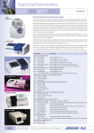
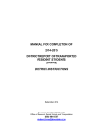
RSE Smart GAS meter RSE/2001 LA – RSE/2,4 Use and Maintenance Manual 169 MHz Rev. 6 Date 17/10/2014 RSE METER Use and Maintenance Manual 169 MHz ENGLISH ISV065UTE Rev.6 Index 1. Introduction .............................................................................................................................................. 5 1.1. Identification of the product ............................................................................................................. 5 1.2. Packaging content ............................................................................................................................. 6 2. Safety instructions .................................................................................................................................. 7 2.1. Electrostatic discharges ..................................................................................................................... 7 2.2. Connecting to other devices ............................................................................................................. 7 2.3. Feeding devices ................................................................................................................................. 7 2.4. Safety instructions for installation in the hazardous area ................................................................. 8 3. General description ................................................................................................................................ 8 4. Main functions ....................................................................................................................................... 10 4.1. On-‐off valve ..................................................................................................................................... 10 4.1.1. Procedure for opening the valve through the user interface .................................................. 10 4.2. Digital outputs ................................................................................................................................. 10 4.3. Data recording ................................................................................................................................. 10 4.4. Acquisition ....................................................................................................................................... 11 4.5. Events and diagnostics .................................................................................................................... 11 4.6. Activation ........................................................................................................................................ 11 4.7. Communication ............................................................................................................................... 11 4.8. User interface .................................................................................................................................. 12 5. Installation .............................................................................................................................................. 12 5.1. Mechanics installation ..................................................................................................................... 12 5.2. Connection to the system ............................................................................................................... 13 5.2.1. 5.3. Using the ZVEI probe ............................................................................................................... 13 Power supply ................................................................................................................................... 14 5.3.1. Connecting the batteries ......................................................................................................... 14 5.3.2. Supply status ........................................................................................................................... 14 5.4. Security and fraud prevention ......................................................................................................... 15 6. User interface ........................................................................................................................................ 16 6.1. Keyboard ......................................................................................................................................... 16 6.2. Display ............................................................................................................................................. 16 6.2.1. Display testing capabilities ...................................................................................................... 16 6.2.2. Menu field ............................................................................................................................... 17 Date of issue 04/06/2014 Revision 6 Revision date 17/10/2014 Page 2 of 31 RSE METER Use and Maintenance Manual 169 MHz ENGLISH ISV065UTE Rev.6 6.2.3. Units of measurement field ..................................................................................................... 17 6.2.4. Numeric field ........................................................................................................................... 18 6.2.5. Icons and alarms field .............................................................................................................. 18 7. Menu structure ...................................................................................................................................... 19 7.1. Chapters .......................................................................................................................................... 19 7.1.1. Date ......................................................................................................................................... 19 7.1.2. Time ......................................................................................................................................... 20 7.1.3. Current rate ............................................................................................................................. 20 7.1.4. Totalizer of volumes under reference conditions in the current billing period ...................... 20 7.1.5. Totalizer of volumes subject to alarm in the current billing period ........................................ 20 7.1.6. Totalizer of volumes for price range 1 in the current billing period ........................................ 21 7.1.7. Totalizer of volumes for price range 2 in the current billing period ........................................ 21 7.1.8. Totalizer of volumes for price range 3 in the current billing period ........................................ 21 7.1.9. Totalizer of volumes under reference conditions in the previous billing period .................... 21 7.1.10. Totalizer of volumes subject to alarm in the previous billing period ...................................... 21 7.1.11. Totalizer of volumes for price range 1 in the previous billing period ...................................... 22 7.1.12. Totalizer of volumes for price range 2 in the previous billing period ...................................... 22 7.1.13. Totalizer of volumes for price range 3 in the previous billing period ...................................... 22 7.1.14. Invoice date ............................................................................................................................. 22 7.1.15. Diagnostics .............................................................................................................................. 23 7.1.16. User Message ......................................................................................................................... 23 7.1.17. Redelivery Point (PDR) ID ........................................................................................................ 24 7.1.18. Status of the valve ................................................................................................................... 24 7.1.19. Status of the device ................................................................................................................. 25 7.1.19.1. Enabling and disabling of the ZVEI port ............................................................................... 26 7.1.19.2. Enabling and disabling of the counting for the test phase .................................................. 27 7.1.20. Maximum conventional flow rate ........................................................................................... 28 8. Configuration ......................................................................................................................................... 29 9. Maintenance .......................................................................................................................................... 29 9.1. 10. Ordinary maintenance .................................................................................................................... 29 9.1.1. Replacing the batteries ............................................................................................................ 29 9.1.2. Firmware update ..................................................................................................................... 29 Technical characteristics ................................................................................................................. 30 Date of issue 04/06/2014 Revision 6 Revision date 17/10/2014 Page 3 of 31 RSE METER Use and Maintenance Manual 169 MHz ENGLISH ISV065UTE Rev.6 10.1. General features .......................................................................................................................... 30 10.2. Communication ports .................................................................................................................. 31 10.3. Feeding devices ........................................................................................................................... 31 Date of issue 04/06/2014 Revision 6 Revision date 17/10/2014 Page 4 of 31 RSE METER ENGLISH Use and Maintenance Manual 169 MHz ISV065UTE Rev.6 1. Introduction RSE is a family of products dedicated to measuring gas volume, which involves the application in end points of redelivery of natural gas networks. This document refers to the versions RSE/2001 LA and RSE/2,4. The product incorporates a mechanical device for measuring the gas volumes based on the diaphragm metering technology with an electronic processor able to guarantee the functions provided by the resolution 631/2013/R/GAS issued by AEEGSI on 27/12/2013, as well as to allow the remote reading and remote control of the flow without the use of additional external devices. RSE meters are used in low pressure measuring systems (<0.5 bar 3 gauge) with a flow rate lower than 10m /h (class A2 according to the classification of UNITS 11291). This document provides information about the use of the involved device. RSE/2001 LA and RSE/2,4 are available in different models with the following main common features: Ø Ø Ø Ø Ø IP 55 protection; Integrated temperature sensor; Local optical communication port complying with CEI EN 62056-21 (ZVEI); LCD display; 3 front keys (user interface); The various models differ in the following features: Ø 1.1. Type of modem: o Wireless M-Bus 169 Mhz mode-N; o 868 Mhz; o GPRS/GSM; Identification of the product The product can be identified by the metrological cover shown in fig.1 positioned on the front of the device as shown in fig.2, which bears the following symbols and data: Ø Ø Type of model; Name of the logic device. Type of model: Code format RSE/2001 LA; RSE/2,4 Name of the logic device: Format SMG-R-03-WV-YY-XXXXXX; SMG Fixed data indicating the manufacturer (Samgas Srl) according to the Flag Association coding; R Reserved; 03 Type of device (GAS meter); W Type of caliber; V Type of communication YY Year of production; XXXXXX Serial number; The forecast product versions are given here below: Version Code “W” Type of caliber Version Code “V” “1” “2” “4” “6” G 1.6 G 2.5 G4 G6 “0” “1” “2” Date of issue 04/06/2014 Revision 6 Revision date 17/10/2014 Type of communication 169 MHz GSM 868 MHz Page 5 of 31 RSE METER ENGLISH Use and Maintenance Manual 169 MHz ISV065UTE Rev.6 Vernate Milano T10627 M14 0122 V 2,4 dm³ Qmin 0,06 m³/h Qt 1 m³/h Qmax 10 m³/h "T" OIML R137-1&2:2012 Vernate Milano EN 1359:1998/A1:2006 G6 T10627 RSE/2,4 M14 0122 Pmax 0,5 bar Classe 1,5 Tm -25°C...55°C Tb 15°C Tsp 15°C V 1,2 dm³ Qmin 0,04 m³/h Qt 0,6 m³/h Qmax 6 m³/h "T" OIML R137-1&2:2012 G4 EN 1359:1998/A1:2006 RSE/2001 LA Pmax 0,5 bar Classe 1,5 Tm -25°C...55°C Tb 15°C Tsp 15°C SMGR034VYYXXXXXX SMGR036VYYXXXXXX 1131 1131 II 3G Ex ic IIB T3 Gc II 3G Ex ic IIB T3 Gc CEC 14 ATEX 011 IP55 CEC 14 ATEX 011 IP55 Fig.1 Fig. 2 1.2. Packaging content The package contains the following parts: Device - RSE device including: o Metrological battery; o Communication battery, not replaceable: o Two plugs for the protection of the connection fittings; The batteries are inside in their operation seat already electrically connected. Date of issue 04/06/2014 Revision 6 Revision date 17/10/2014 Page 6 of 31 RSE METER Use and Maintenance Manual 169 MHz ENGLISH ISV065UTE Rev.6 Manual - User Manual: The user manual and the use and maintenance manual are available for download on the website www.fiorentini.com Certificates The EC declaration of conformity is enclosed to the transport documents of the instrument 2. Safety instructions RSE is an intrinsically safe device suitable for use in hazardous areas classified as Zone 2 Group IIB. The minimum installation category is ATEX Category II 3G. The harmonized CENELEC standards relevant to the compliance with the EHSR requirements (Essential Health and Safety Requirements) of the ATEX Directive are EN 60079-0 and EN 60079-11. This device is designed to comply with the requirements of the type of protection Ex ic IIA T3 Gc, ambient temperature range -25°/55°C and ATEX category II 3G. 2.1. Electrostatic discharges This device is approved for installation in areas with low explosion risk (risk only for short periods). In these areas, sparks produced from electrostatic discharges could generate explosions in extreme cases. Although during normal operation there is no presence of dangerous potentials on the device, the use of dissipative footwear and of a damp cloth (% > 65%) is recommended during the installation/maintenance. Further information can be found in CEI 50404. During the installation or use of this instrument, it is advisable to take steps to assure protection against electrostatic discharges. Samgas Srl denies all liabilities resulting from the risks and consequences caused by the non-compliance with these provisions 2.2. Connecting to other devices There is no RSE connection with external devices. RSE can connect, using the ZVEI optical port, to devices for the communication of data and commands useful for configuration and maintenance of the device. RSE can connect, using the GSM modem/wireless radio port, to local and/or remote devices for the communication of the data and commands useful for configuration, management, and maintenance of the device. 2.3. Feeding devices RSE can be powered exclusively by a special approved battery pack. As a matter of fat, the battery pack is a proprietary assembly consisting of a lithium battery and a cable ending with a special connector, coated by a protective sheath. The battery pack is a device certified for exclusive use with the RSE device and it is the only permissible power supply device. Caution! Use only batteries of the type and model complying with the original. The connector of the battery pack is polarized in such a way as to fit only in the connector specifically provided for on the device, observing the correct polarity. Date of issue 04/06/2014 Revision 6 Revision date 17/10/2014 Page 7 of 31 RSE METER Use and Maintenance Manual 169 MHz ENGLISH ISV065UTE Rev.6 The following data are given on the battery pack: • Model; • Maximum output levels; • Week and year of production • Quality pass upon acceptance The metrological battery pack is sufficient to assure an autonomy of at least 15 years under the reference operating conditions specified in paragraph Technical features. The transmission battery pack for the 169 MHz radio module is sufficient to assure an autonomy of at least 15 years under the reference operating conditions specified in paragraph Technical features. 2.4. Safety instructions for installation in the hazardous area This equipment has to be installed and operated in compliance with the provisions and regulations in force. The manufacturer cannot be liable for damages resulting from failure to follow instructions and inappropriate use. Safety warning All works must be performed by qualified personnel. Transformation of spare parts Any technical changes are forbidden. Use only original spare parts. Transport As a rule, meters shall be transported being kept in vertical position. Upon receipt of the product, examine the supplied material. Immediately notify any shipping damage. Storage As a rule, meters have to be stored in vertical position and in a dry place at ambient temperature. WARNING • • • • • • • Install in a compartment that meets the provisions in force on safety, away from any possible damage of mechanical origin, away from sources of heat or open flames, in a dry place and protected from external agents; Install with the indicator device in a horizontal position, not in contact with the wall and raised with respect to the floor; During installation, avoid mechanical stress to the inlet and outlet connections; The arrow on the top of the meter indicates the direction of the gas flow; The on/off valve, positioned in the system upstream of the meter, has to be opened in a gradual manner in order to make the gas flow homogeneously, without violent shocks that could damage the internal components of the meter; It is strictly forbidden to repair or make any modifications to the instrument; The installation, removal, and any works in general have to be performed by qualified personnel, in compliance with the provisions in force concerning safety. 3. General description Figures 3 and 4 illustrate the structure and the main parts of the device. The device consists of: A metal enclosure containing in it: • The mechanics for measuring the volumes complying with that of the RS/2001 meter; • The flow on/off valve; • The sensor for measuring gas temperature; • The permanent memory device (see paragraph 4.3 data recording); A plastic enclosure containing in it: • The electronic measurement and communication card; • The battery(batteries) On the front of the plastic container there are: • A segment and icon display; • Three operator keys; • Optical communication interface. Date of issue 04/06/2014 Revision 6 Revision date 17/10/2014 Page 8 of 31 RSE METER Use and Maintenance Manual 169 MHz ENGLISH ISV065UTE Rev.6 Metal enclosure Plastic enclosure Fig.3 RSE/2001 LA View Metrological battery Radio transmission battery, not replaceable PCB card GSM transmission battery compartment Fig. 4 – Meter internal view RSE is a measuring instrument with accuracy class 1.5 or 1 (upon request), as defined in Directive 2004/22/EC (MID). RSE is able to count the amount of gas that has passed through the meter in different consumption ranges in relation to the time in which it was measured, in compliance with the provisions of the resolution 631/2013/R/GAS issued by AEEGSI on 27/12/2013. Date of issue 04/06/2014 Revision 6 Revision date 17/10/2014 Page 9 of 31 RSE METER Use and Maintenance Manual 169 MHz ENGLISH ISV065UTE Rev.6 4. Main functions 4.1. On-off valve With reference to the standards of the series UNI/TS 11291, RSE implements in particular the following services: UNI/TS 11291-1 4.3.4 Service: Supply management UNI/TS 11291-6 6 Flow on/off The gas flow on/off valve is located within the body of the meter into the inlet connection and is not accessible without causing permanent damage to the meter itself. The purpose of the valve is to intercept the gas flow towards the user exclusively for the commercial purposes. In no way or condition, the valve has to be considered and used as a useful device to assure safety conditions in the user's plant in case of possible or patent gas leakages. The valve is specifically designed to assure its performance and functioning for at least 15 years and it is able to provide the control microprocessor with the actual status of the valve (closed/open) and with information about its correct operation. The valve can be closed: • Due to a remote control sent via wireless communication channel (e.g.: from the SAC Remote Management Center); • When changing the battery is not authorized; • Due to a break-in attempted beyond the threshold; • When there is no communication for a configurable time; • When the residual battery power is below the critical level; • In case of failure of the Gdm system. The previously closed valve, can be opened only locally by activating the keyboard according to a special procedure (see chapter 4.1.1) The opening of the previously closed valve must be authorized in advance by the SAC - Control Center. It is possible to display the status of the valve in the related SV menu (see chapter 6 and chapter 7.1.18). To reactivate a previously closed valve, RSE must have first of all received the "authorization for opening" from the Control Center. 4.1.1.Procedure for opening the valve through the user interface After receiving permission for opening the valve from SAC, with a set time window useful to perform such operation and the maximum number of possible attempts, under the SV valve menu the following will appear on the display: VAL 40 r valve enabled to be opened Press ENTER to access the submenu. Under the VP menu, the message PSSD (password requested) appears; press ENTER to enter the four digits of the password to be entered (the operator must have the password). Use the up and down buttons to select the digit to be set, once the desired digit is displayed, press ENTER to confirm it. Repeat the same operation for all four digits. After selecting the last digit and having pressed ENTER, press again ENTER to start the opening of the valve. At the end of the occurred opening the display shows the message "SUCCESS". Under the SV menu, the display will show: VAL 00 A 4.2. open valve Digital outputs RSE does not have any digital outputs 4.3. Data recording With reference to the standards of the series UNI/TS 11291, RSE implements in particular the following services: UNI/TS 11291-1 4.3.3 Service: Dynamic multi-rate capacity UNI/TS 11291-1 4.3.7 Service: Metering and load profiles UNI/TS 11291-6 5 Detection and recording of data Date of issue 04/06/2014 Revision 6 Revision date 17/10/2014 Page 10 of 31 RSE METER Use and Maintenance Manual 169 MHz ENGLISH ISV065UTE Rev.6 4.4. Acquisition The flow rate measurement is carried out continuously by means of the mechanical system consisting of two measuring chambers (of known volume) with deformable diaphragms, which expand and contract alternately. This movement, induced by the pressure difference between the inlet and outlet passages, operated by a crank mechanism, is transmitted to a pin that makes a complete turn every cyclic volume of gas passing through. The movement of the pin causes the rotation of an encoder; such rotation is detected by means of two optical sensors. The management of both HW and SW is carefully optimized to minimize the consumption of the measuring circuit and the processor awakening time. The optical sensor provides sufficient resolution to allow the measurement of the amount of gas, both during operation and for the certification/production/calibration steps, using in this case a modified counting algorithm. The two pairs of LED phototransistor sensors are positioned at 90° to one another. For each rotation of the encoder divided into full and empty sectors, a given sequence of statuses is therefore available. The coding of this sequence allows identifying a regular counting, a reverse rotation, or an oscillation. In this way, it is possible not to affect the taken measurement in any way. The system, consisting of an encoder and optical sensors, represents the interface between the measuring mechanics and the calculation and management electronics. The piloting and detection of the optical sensors is entrusted directly to the microprocessor, which performs also an ongoing diagnostic activity to highlight any faults and fraud attempts made by blinding the sensors. The piloting of the sensors is carried out in a controlled manner, which is such as to assure proper operation during the whole RSE life-cycle. The measurement of the temperature, required for the calculation of the volumes on the reference thermodynamic conditions, is carried out using a temperature sensor with a resolution of 10 bits, which provides a measurement in Kelvin degrees with a resolution of 0.25°C in a time span of 50ms. The measurement of the gas temperature is acquired and updated every 30 s. 4.5. Events and diagnostics With reference to the standards of the series UNI/TS 11291, RSE implements in particular the following services: UNI/TS 11291-1 4.3.9 Service: Detection and reporting of anomalies UNI/TS 11291-6 7.1 Functional Requirements - Event Log UNI/TS 11291-6 7.6 Functional Requirements - Diagnostics and alarms 4.6. Activation With reference to the standards of the series UNI/TS 11291, RSE implements in particular the following services: UNI/TS 11291-1 4.3.1 Service: Synchronization UNI/TS 11291-1 4.3.6 Service: Software updating UNI/TS 11291-1 4.3.8 Service: Management and Maintenance of the infrastructure UNI/TS 11291-6 7.3 Functional Requirements - Programming UNI/TS 11291-6 7.4 Functional Requirements - Operations concerning commissioning and maintenance UNI/TS 11291-6 7.5 Functional Requirements - Clock 4.7. Communication RSE has two communication interfaces, a local one and a remote one: Local interface: Optical port Infrared port complying with the standard EN 62056-21; it requires an external device (ZVEI probe); The protocol used for the ZVEI optical port is DLMS. The asynchronous format and the speed of the optical port are set to the following values: Speed: 9600 baud, format: 1(start bit), 8 (data bit), N (no parity), 1 (stop bit) The ZVEI optical port is normally off. To enable it, follow the instructions given in chapter 7.1.19.1 Remote interface: WMbus modem Integrated in the device, antenna included and not remotizable; The WMbus modem, including the antenna, is integrated in the meter. Date of issue 04/06/2014 Revision 6 Revision date 17/10/2014 Page 11 of 31 RSE METER ENGLISH Use and Maintenance Manual 169 MHz ISV065UTE Rev.6 4.8. User interface The user interface consists of a LCD display and three operator keys. The interface allows only the consultation of the parameters and provides access to the SD “status of the device” menu. 5. Installation RSE is suitable for installation in hazardous areas classified as ATEX Zone 2. RSE meets the protection requirements of type: II 3G Ex ic IIB T3 Gc. 3G: For use in Zone 2 atmospheres; therefore, it is safe in case of operation without interferences. IIB: It establishes the maximum ignition energy that shall not be exceeded and, therefore, with what types of gas the product can be used in a safe manner (e.g.: ethylene). T3: It defines the maximum allowable surface temperature equal to 200 °C. Caution! Before beginning with the installation, read and verify the safety instructions contained in the first chapter carefully 5.1. Mechanics installation The overall dimensions of RSE are shown below. RSE is fastened to the system using a special shelf for GAS meter. 172.5 190 110 RSE/2001 LA 223 G4 68 Model RSE/2001 LA 179 341.5 74 250 RSE/2,4 246 G6 Model RSE/2,4 Fig. 5 – Overall dimensions Date of issue 04/06/2014 Revision 6 Revision date 17/10/2014 Page 12 of 31 RSE METER Use and Maintenance Manual 169 MHz ENGLISH ISV065UTE Rev.6 5.2. - Connection to the system After installation, RSE must be connected to the system. Before connection, make sure that at least the portion of the plant upstream of the meter is sectioned and that, therefore, there cannot be any flow of gas during the installation; Before connection, make sure that the maximum system pressure is lower than the maximum pressure set for the meter, which is fixed and equal to 0.5 relative bar; If necessary, use fittings (not supplied) to connect RSE to the piping. During the tightening of the fittings, do not exceed the torque of 110Nm; RSE operates only in vertical position; RSE is provided with an on/off valve in the "open" status; therefore, it is ready to deliver and measure. Verify that the utilities on the customer side are closed. Slowly load the RSE meter with pressure. If on the meter a piping for pressure measurement has been subsequently installed, check the tightness of the related connection. After leak testing, slowly remove pressure to the RSE meter. Once the tightness has been checked, the meter is ready for use. The meters of the company SAMGAS require no maintenance. WARNING When the meter is disassembled, it may contain a residual amount of gas. Considering the danger of explosion, it is necessary to take safety measures, e.g.: – After disassembling the RSE meter, clean it very well with an inert gas. – For transporting the meter with residual amounts of gas, use a vehicle with an open or vented loading area. 5.2.1.Using the ZVEI probe The ZVEI probe (available as an option) is equipped with magnetic coupling. Place the probe in the provided groove on the front part of RSE with the cable facing downwards. The magnet and the groove will retain the probe in place. To enable the communication on the ZVEI optical port, it is sufficient to let the display show the SD menu. Date of issue 04/06/2014 Revision 6 Revision date 17/10/2014 Page 13 of 31 RSE METER Use and Maintenance Manual 169 MHz ENGLISH ISV065UTE Rev.6 5.3. Power supply The RSE meter can be powered exclusively by batteries. The metrological battery is dimensioned to assure the operation of RSE for at least 15 years. The battery autonomy was estimated in the following reference operating conditions: The 169 MHz radio transmission battery is dimensioned to assure the operation of RSE for at least 15 years. The battery autonomy was estimated in the following reference operating conditions: 169 MHz Radio Communication: Tx Only radio cycle – Short Message (volume reading) transmitted - 5 messages/day Tx-Rx radio cycle – Tx-Rx talks with long message Display message/ZVEI communication 5 minutes per month Valve control: 1 complete control (including 1 opening and 1 closing) every year 1 valve test period (valve periodic test) 1 cycle per month Ambient temperature profile: 5% of the time at -25°C; 20% of the time at -10°C; 50% of the time at 22°C; 20% of the time at 55°C; 5% of the time at 70°C. RSE implements and manages service quality logs, available only through the communication channels (not on the display) able to verify the deviation of the actual operating conditions from the reference ones. 5.3.1.Connecting the batteries RSE is supplied with the metrological battery already connected and inserted in the related compartment; therefore, RSE is ready for operation. 5.3.2.Supply status Power status shows the current battery level. The functionality of calculation of the actual use of the battery has been implemented in order to signal when the limit of 90% is reached. A weight has been configured for the main activities of the device (periodic and not). Therefore the actual consumption of the battery is calculated according to the time elapsed, the individual functions actually performed and the weight in terms of consumption. When this estimate exceeds 90% of the value set as threshold, the appropriate alarm event is generated. Date of issue 04/06/2014 Revision 6 Revision date 17/10/2014 Page 14 of 31 RSE METER ENGLISH Use and Maintenance Manual 169 MHz ISV065UTE Rev.6 5.4. Security and fraud prevention The solutions implemented on the RSE meter to assure the security comply with the requirement set forth by the standard UNI TS 11291. With reference to the standards of the series UNI/TS 11291, RSE implements in particular the following services: UNI/TS 11291-1 4.3.2 Service: Detection and reporting of fraud UNI/TS 11291-1 4.3.10 Service: Security Management UNI/TS 11291-6 7.2 Functional Requirements - Access RSE implements all security policies defined by the reference standards and, in particular, by UNI TS 11291. In detail: Access to the electronics is not possible without removing the mechanical and metrological seal and without permanently damaging the metrological cover; Access to the memory device is not possible without permanently and patently damaging the meter; Access to the flow on/off valve and the temperature sensor is not possible without permanently and patently damaging the meter; Access to the metrological battery and to the non-replaceable transmission battery is not possible without removing the mechanical and metrological seal and without permanently damaging the metrological cover; Access to the replaceable communication battery is not possible without leaving a record of the event in the Metrological Log of the meter; Using interface equipment usually available to the user it is only possible to read the data and it is not possible to perform any configuration; The configurations that can be performed through the communication channels with which the device is equipped - which can be carried out only by authorized personnel - leave a track as they are stored in the relevant memory log (Metrological Log); Attempts to tamper with the proper functioning of the meter are detected and recorded in the Metrological Log; Attempts to access the meter through the communication channels with which it is equipped by unauthorized personnel are detected and recorded in the Metrological Log; The commands sent by external devices through the communication channels with which the device is equipped are verified in terms of the source authenticity; The messages transmitted through the communication channels conveying sensitive information are all efficiently encrypted; Attempts to access the meter through the communication channels made with wrong passwords or encryption keys are detected, listed and made available to the control center; The duration of the conditions is monitored and recorded. Metrological seal Metrological seal Date of issue 04/06/2014 Revision 6 Revision date 17/10/2014 Anti-tampering device Page 15 of 31 RSE METER ENGLISH Use and Maintenance Manual 169 MHz ISV065UTE Rev.6 6. User interface The user interface consists of three operator keys and a display. The following paragraphs describe the interaction between the operator and the user interface, and the meanings of the various fields available on the display. With reference to the standards of the series UNI/TS 11291, RSE implements in particular the following services: UNI/TS 11291-1 4.3.5 Service: Consumer information UNI/TS 11291-6 8.2 Construction requirements - Display 6.1. Keyboard The interaction occurs through three keys: up and down scrolling (blue color) and Enter (green) on the front of the device. 6.2. Display The display is a black and white LCD display consisting of 8 7-segment characters and a series of icons and symbols whose meaning is described below. The size of the digits represented by the 8 7-segment characters are compatible with the requirements of MID and EN12405-1. The construction technology of the LCD element (display) is such as to assure a lifetime of over 15 years under operating conditions which include also prolonged exposure to sunlight. Menu field Units of measurement field Numeric field Icons and alarms field The meaning of the graphical elements is outlined in the following table: Menu field Each menu can be identified by a letter or a combination of letters and numbers Units of measurement field See table for units of measurement Numeric field 8 7-segment digits displaying the value associated with the displayed menu Icons and alarms field See table for icons and alarms To allow a long battery life, the display is usually kept OFF. To activate it, just press the green central key. 6.2.1. Display testing capabilities When the display is turned off and the green central key is pressed, a test sequence is displayed to check the presence of defective segments or icons. The test sequence lasts 3 seconds and turns on all segments and icons of the display at the same time. At the end of this step, the first page of the menu is displayed. Date of issue 04/06/2014 Revision 6 Revision date 17/10/2014 Page 16 of 31 RSE METER Use and Maintenance Manual 169 MHz ENGLISH ISV065UTE 6.2.2.Menu field Icon Meaning Notes Date Hour Current price range Totalizer of volumes under reference conditions Totalizer of volumes subject to alarm Totalizer of volumes under reference conditions for range 1 Totalizer of volumes under reference conditions for range 2 Totalizer of volumes under reference conditions for range 3 When the count refers to previous billing periods Added to T, TA, T1, T2 or T3 Invoice date Diagnostics Message to the user ID of the re-delivery point Status of the valve Status of the device Maximum conventional flow rate 6.2.3. Units of measurement field Icon Meaning Notes When a temperature value is displayed When a pressure value is displayed When a volume value is displayed When a flow rate value is displayed Used together with the icon Date of issue 04/06/2014 Revision 6 Revision date 17/10/2014 Page 17 of 31 Rev.6 RSE METER ENGLISH Use and Maintenance Manual 169 MHz ISV065UTE Rev.6 6.2.4. Numeric field It consists of 8 7-segment digits and gives the value associated with the displayed menu page. 6.2.5. Icons and alarms field Icon Description ON Communication Radio communication active General warning Active alarm Low battery Low battery to be replaced (residual charge <10%) Temperature alarm Active alarm Authentication required Authentication required to access the submenu functions Authentication performed Authentication occurred. It is possible to access the submenus Available scrolling keys Available scrolling keys to navigate the submenus Enter key available Enter key available Date of issue 04/06/2014 Flashing Revision 6 Alarm not active but previously recorded and not yet displayed Alarm not active but previously recorded and not yet displayed Revision date 17/10/2014 Page 18 of 31 RSE METER Use and Maintenance Manual 169 MHz ENGLISH ISV065UTE Rev.6 7. Menu structure This section shows the hierarchy of the pages making up the interface with the user. Under normal operating conditions, the display is completely off. Pressing the green Enter key, the display turns on and performs a test in which all segments and icons are lit simultaneously for three seconds. At the end of the test, the first page of the menu is displayed. If not any key is pressed for about two minutes, the display returns to off status. By pressuring the up and down keys, it is possible to navigate through the various menus. Pressing the up button, it is possible to go back to the previous page; pressing the down button, it is possible to move to next page. Some menus consist of various submenus; in this case, the letter E (Enter) is displayed on the lower right corner of the display. By pressing the green Enter button, the submenu appears. By pressing the up and down buttons, it is possible to navigate inside the submenus. 7.1. Chapters The various menus are identified by the letters shown on the display under "menu field". Here below, there are the menus displayed in sequence, scrolling down after switching on the display. The sequence is circular; the list can be scrolled indifferently downwards and upwards. Once the corresponding end is reached, the display continues in the order defined below. 7.1.1. Date Abbreviation Format Unit Pressing enter Legal relevance D dd-mm-yy E By pressing enter, it is possible to display the version CRC of the certificate modules and other information on the software. The submenus are listed below: • CRC16 Legally Relevant SW • Legally Relevant SW internal release • CRC16 Not Legally Relevant SW • Not Legally Relevant SW internal release • Release date • Release time • CRC16 Boot module • CRC16 Header module • CRC16 Loader module • CRC16 Hal module • CRC16 Kernel module • CRC16 Stm32lib module • CRC16 KSystem module • CRC16 Security module • CRC16 Display module • CRC16 Metric module • CRC16 Plugin header • CRC16 Plugin module • System global uptime (days) including low power and running mode • System global uptime (h-m-s) including low power and running mode • System running mode uptime (days) • System running mode uptime (h-m-s) • Total number of events • Code started events • Consid. param modified events • Security param modified events • New SW run events • Upgrade errors • Total CRC errors (Kernel + Data) • Kernel only CRC errors • Attempted fraud events YES Date of issue 04/06/2014 Revision 6 Revision date 17/10/2014 Page 19 of 31 RSE METER Use and Maintenance Manual 169 MHz ENGLISH ISV065UTE 7.1.2. Time Abbreviation Format Unit Pressing enter H hh-mm E By pressing enter, it is possible to view the log of the last 32 firmware updates. For each firmware updates a block of three submenus is added: • CRC16 LR of the firmware • Updating date • Updating time Legal relevance The firmware loaded at the factory is the oldest entry (date and time set to 00-00-00). If the download fails, four dashes (“----“) are displayed instead of CRC 16 LR. YES 7.1.3. Current rate Abbreviation Format Fn 1 digit Possible values: Unit Pressing enter Legal relevance YES • • • 1 2 3 Range 1 Range 2 Range 3 7.1.4. Totalizer of volumes under reference conditions in the current billing period Abbreviation Format Unit Pressing enter Legal relevance T 5 integers and 3 decimals m³ YES 7.1.5. Totalizer of volumes subject to alarm in the current billing period Abbreviation Format Unit Pressing enter Legal relevance TA 5 integers and 3 decimals m³ YES Date of issue 04/06/2014 Revision 6 Revision date 17/10/2014 Page 20 of 31 Rev.6 RSE METER Use and Maintenance Manual 169 MHz ENGLISH ISV065UTE 7.1.6.Totalizer of volumes for price range 1 in the current billing period Abbreviation Format Unit Pressing enter Legal relevance T1 5 integers and 3 decimals m³ YES 7.1.7. Totalizer of volumes for price range 2 in the current billing period Abbreviation Format Unit Pressing enter Legal relevance T2 5 integers and 3 decimals m³ YES 7.1.8. Totalizer of volumes for price range 3 in the current billing period Abbreviation Format Unit Pressing enter Legal relevance T3 5 integers and 3 decimals m³ YES 7.1.9.Totalizer of volumes under reference conditions in the previous billing period Abbreviation Format Unit Pressing enter Legal relevance T PRE 5 integers and 3 decimals m³ YES 7.1.10. Totalizer of volumes subject to alarm in the previous billing period Abbreviation Format Unit Pressing enter Legal relevance TA PRE 5 integers and 3 decimals m³ YES Date of issue 04/06/2014 Revision 6 Revision date 17/10/2014 Page 21 of 31 Rev.6 RSE METER Use and Maintenance Manual 169 MHz ENGLISH ISV065UTE 7.1.11. Totalizer of volumes for price range 1 in the previous billing period Abbreviation Format Unit Pressing enter Legal relevance T1 PRE 5 integers and 3 decimals m³ YES 7.1.12. Totalizer of volumes for price range 2 in the previous billing period Abbreviation Format Unit Pressing enter Legal relevance T2 PRE 5 integers and 3 decimals m³ YES 7.1.13. Totalizer of volumes for price range 3 in the previous billing period Abbreviation Format Unit Pressing enter Legal relevance T3 PRE 5 integers and 3 decimals m³ YES 7.1.14. Invoice date Abbreviation Format Unit Pressing enter Legal relevance DF dd-mm-yy YES It expresses the date on which the data of the previous period do refer (T/TA/T1/T2/T3 PRE) Date of issue 04/06/2014 Revision 6 Revision date 17/10/2014 Page 22 of 31 Rev.6 RSE METER ENGLISH Use and Maintenance Manual 169 MHz ISV065UTE Rev.6 7.1.15. Diagnostics Abbreviation Format Unit Pressing enter Legal relevance DG 4 digits (hexadecimal code) YES The encoding of the information shown complies with the provisions of the standard UNIT11291-11-, chapter 5.4.9.2, given here below. Bit 15 14 13 12 11 10 9 8 7 6 5 4 3 2 1 0 Meaning Reserved Reserved Reserved 1 = Valve enabling anomaly 1 = Daylight Saving Time active 1 = Tampering detected 1 = Battery level critical 1 = Battery level lower than 10% 1 = Device not configured or under maintenance; 0 = device configured 1 = Memory error 1 = Flow rate error 1 = Device generic error 1 = Measurement algorithm error 1 = Metrological Event Log ≥ 90% 1 = Metrological Event Log complete 1 = Clock synchronization failed The 16 bits mentioned above are represented using a hexadecimal encoding (0 – F) by sets of 4, as shown below: BIT DIGIT 15 14 13 4 12 11 10 3 9 8 7 6 2 5 4 3 2 1 1 0 Example: Diagnostics: Hexadecimal encoding: 0 8 0 2 Binary encoding: 0000 1000 0000 0010 Meaning: Bit 1 = 1 à Metrological Event Log complete Bit 11 = 1 à Dayligth saving time ( ora legale) attiva 7.1.16. User Message Abbreviation Format Unit Pressing enter Legal relevance MU Text - 100 characters NO User message; information displayed pursuant to the provisions of the standard UNITS 11291-11-1, chapter 5.4.8.13. Date of issue 04/06/2014 Revision 6 Revision date 17/10/2014 Page 23 of 31 RSE METER Use and Maintenance Manual 169 MHz ENGLISH ISV065UTE Rev.6 7.1.17. Redelivery Point (PDR) ID Abbreviation Format Unit Pressing Enter ID 14 digits E By pressing enter, it is possible to scroll the 14 digits in both directions using the arrow keys. Legal relevance Yes Redelivery Point (PDR) ID 7.1.18. Status of the valve Abbreviation Pressing Enter SV Press the central button to access the valve menu The menu structure is shown below: To enter the password using the up and down buttons to select the numbers; then, press the enter button to confirm. To perform the leak testing, press the Enter button. Here below, there are all the submenus: menu id VAL Legal relevance VR VT VP Operation 00 A 00 C 00 r Nn Nn PSSD VL nn Description Open valve Closed valve Valve enabled to be opened VR remaining time VT number of attempts VP password entering Up and down to select Enter to confirm VL leak testing and result (dm3) NO Date of issue 04/06/2014 Revision 6 Revision date 17/10/2014 Page 24 of 31 RSE METER Use and Maintenance Manual 169 MHz ENGLISH ISV065UTE Rev.6 7.1.19. Status of the device Abbreviation Format SD 1 digit – Possible values: • -2 production • -1 factory • 0 device configured • 1 device under maintenance • 3 device not configured E Pressing the central button, access is granted to the maintenance menu. The menu structure is shown below 2 decimal digits define the menu id 2 decimal digits define the operation id 2 decimal digits define the operation result To perform the maintenance test, if allowed, it is necessary to press the central button. Here below there is a list of submenus: Unit Pressing Enter Legal relevance menu id 01 operation 01 result 00-01 01 02 00-01-02 01 03 00-01-02 02 01 00-01 02 02 00-01-02 02 03 00-01-02 03 04 - 00-07 99 - - Description ZVEI port status 00 = disabled 01 = enabled Enabling the ZVEI port. 00 = operation not yet preformed 01 = operation performed successfully 02 = operation failed Disabling the ZVEI port. 00 = operation not yet preformed 01 = operation performed successfully 02 = operation failed Counting resolution status 00 = Normal resolution 01 = Resolution subject to testing Setting of the counting resolution 00 = operation not yet preformed 01 = operation performed successfully 02 = operation failed Setting of the normal resolution 00 = operation not yet preformed 01 = operation performed successfully 02 = operation failed Display of the read temperature Setting of the display contrast. Press enter, and then the up/down keys to select the desired contrast value for the LCD display; then, press enter to confirm. Exit Press enter to close the maintenance menu and return to the main menu. NO Date of issue 04/06/2014 Revision 6 Revision date 17/10/2014 Page 25 of 31 RSE METER Use and Maintenance Manual 169 MHz ENGLISH ISV065UTE 7.1.19.1. 1. Enabling and disabling of the ZVEI port From the main SD menu, press the central button to access the submenu ZVEI port status: Disabled 2. Press the lower button once Submenu to enable the ZVEI port 3. Press the central button The operation was completed successfully 4. Press the upper button once ZVEI port status: Enabled 5. Press the lower button twice Submenu to disable the ZVEI port Date of issue 04/06/2014 Revision 6 Revision date 17/10/2014 Page 26 of 31 Rev.6 RSE METER Use and Maintenance Manual 169 MHz ENGLISH ISV065UTE 6. Press the central button The operation was completed successfully 7. Press the upper button twice ZVEI port status disabled 7.1.19.2. Enabling and disabling of the counting for the test phase 1. From the main SD menu, press the central button to access the submenu 2. Press the lower button three times The meter is counting with normal resolution 3. Press the lower button Menu to set the counting in high resolution 4. Press the central button The operation was completed successfully 5. Press the upper button The meter is counting with high resolution Date of issue 04/06/2014 Revision 6 Revision date 17/10/2014 Page 27 of 31 Rev.6 RSE METER Use and Maintenance Manual 169 MHz ENGLISH ISV065UTE 6. Press the lower button twice Menu to set the counting in low resolution 7. Press the central button The operation was completed successfully 8. Press the upper button twice The meter is counting with normal resolution 7.1.20. Maximum conventional flow rate Abbreviation Format Unit Pressing Enter Legal relevance Qconv_max 2 integers and 3 decimals m³/h YES Date of issue 04/06/2014 Revision 6 Revision date 17/10/2014 Page 28 of 31 Rev.6 RSE METER Use and Maintenance Manual 169 MHz ENGLISH ISV065UTE Rev.6 8. Configuration The device configuration can occur from the local ZVEI port or remotely from SAC, always by means of the DLMS protocol, as specified in the provisions of the standards series UNI/TS 11291. 9. Maintenance 9.1. Ordinary maintenance 9.1.1.Replacing the batteries The RSE metrological battery is sized to assure an autonomy of more than 15 years under normal environmental and operating conditions (see paragraph 10.3) and, therefore, it is not necessary to replace it. The 169 MHz transmission battery is sized to assure an autonomy of more than 15 years under normal environmental and operating conditions (see paragraph 10.3) and, therefore, it is necessary to replace it. 9.1.2.Firmware update In case of release of a new firmware version, the notes that describe the changes made since the previous version are distributed. The firmware update can easily be performed also remotely. Contact Samgas for further details Date of issue 04/06/2014 Revision 6 Revision date 17/10/2014 Page 29 of 31 RSE METER Use and Maintenance Manual 169 MHz ENGLISH ISV065UTE Rev.6 10. Technical characteristics 10.1. General features Parameter Features Enclosure Main body: Polycarbonate Transparent cover: Polycarbonate Protection degree IP 55 Dimensions (overall) RSE/2001 LA Max 223(H) x 190(L) x 172,5(P) RSE/2.4 Max 246(H) x 341,5(L) x 179(P) RSE/2001 LA 110 mm RSE/2.4 250 mm Methane gas, town gas, propane and butane UNI EN 437:2003 Distance Type of gas gas from the first to the third family Operating pressure 0.5 bar Display Black and white LCD with segments Resistance to high temperatures "T" Resistance to high temperatures Keyboard 3-front operator keys Operating/storage temperature -25°C to +55°C / -25°C to +60°C Certifications Atex (Ex ic 3G IIB T3 Gc), MID Metrological battery Type: 3.6 V lithium battery Format: Size C Autonomy: >15 years Type: 3.6 V lithium battery Format: Size C Autonomy: >15 years Microprocessor STM32L152 32 bit Code memory 384 Kbyte of Flash type Data memory Type: EEPROM 12 Kbyte Data memory >20 years Transmission battery Real Time Clock EN 1359:1998+A1:2006, paragraph 6.5.5 RTC always active Accuracy according to EN62054-21 Accuracy Accuracy class 1.5/1 According to MID (*) Operating conditions Ambient temperature Ta min (-25°C) Flow rate Max Use of user interface 5 minutes per month Valve control 1 cycle per year Code update 2 every 15 years Date of issue 04/06/2014 Revision 6 Revision date 17/10/2014 Page 30 of 31 RSE METER Use and Maintenance Manual 169 MHz ENGLISH ISV065UTE Rev.6 10.2. Communication ports Parameter Features Local communication port Physical level ZVEI (IEC 62056-21) Speed 9600 baud Application level Protocol DLMS 10.3. Feeding devices RSE can ONLY be fed by a separate approved battery pack. Metrological battery The feeding of the metrological equipment is guaranteed by a non-rechargeable lithium battery with a duration > 15 years under reference operating conditions (see table below). A single, non-rechargeable, cell with Lithium – Thionyl chloride technology (Li-SOCl2) is used The main features are: Size C with Bobbin technology; Rated voltage equal to 3.6 Vdc. Rated capacity of about 8.5 Ah. The Bobbin technology assures a maximum current limited by significant intrinsic internal resistance; however, it still provides sufficient current for the device operation. Wiring with polarized connector, to assure proper connection to the printed circuit board. The cell is fastened inside the meter; it cannot be replaced and it is protected by metrological seals. 169 MHz radio battery The radio version has an additional non-replaceable battery, placed in the metrological area and, therefore, not accessible by the operator. A single, non-rechargeable, cell with Lithium – Thionyl chloride technology (Li-SOCl2) is used The main features are: Size C with spiral technology; Rated voltage equal to 3.6 Vdc. Rated capacity of about 7.0 Ah. The spiral technology allows the battery to provide peak currents appropriate for the operation of the enhanced 169 MHz radio battery. Wiring with polarized connector, to assure proper connection to the printed circuit board. The cell is fastened inside the meter; it cannot be replaced and it is protected by metrological seals. Reference operating conditions Amb. temperature 5% of the time 20% “ 50% “ 20% “ 5% “ Communication: Tx radio cycle Short message (volume measurement) transmitted @ -25°C @ -10°C @ 22°C @ 55°C @ 70°C Tx-Rx talks with long message 5 messages sent per day 1 command / day User interface 5 minutes per month Display/buttons/ZVEI Temperature measurement 1 measurement every 29 sec Flow rate Qmax Code update 2 times in 15 years Tx-Rx radio cycle Date of issue 04/06/2014 Revision 6 Revision date 17/10/2014 Page 31 of 31