1
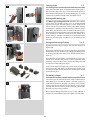
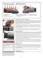
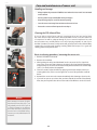
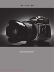
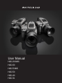
H4D
User Manual
H4D-200MS
H4D-60
H4D-50MS
H4D-50
H4D-40
H4D-31
H4D
1
$BSSZJOHTUSBQ
2
The carrying strap is attached by firstly withdrawing the safety
collar. The hook is then freed and attached to the strap lug (fig. 1).
Slide back the safety collar (fig. 2) to ensure the hook remains in
the locked position between the small protruding lugs. The collar
is purposely a tight fit and might need some effort to slide.
Rechargeable battery grip
3
The Battery grip rechargeable 7.2V (3043348) is the standard
power source for the H4D camera and is an environmentally
approved Li-ion type. The H4D requires a power supply for all
actions as there is no mechanical reserve facility. When working
untethered, it is therefore advisable to keep a reserve rechargeable battery grip at hand. As is the case with most batteries, problems might be encountered when used in very low temperatures.
In this situation it is advisable to keep the reserve battery in an
inside pocket, for example, to maintain it near body temperature
(both sorts of battery grips are referred to as the ‘battery’ in this
manual).
4
C
1
A
B
Fitting and removing a battery
5
3, 4, 5
The fitting and removing procedure is the same for both types of
battery grip.
Remove the battery from the camera by depressing the battery
holder button (A) and simultaneously swinging the battery holder retaining lever (B) down until it stops. Pull the battery downwards (C).
If you intend to store the battery separately from the camera you
should ensure that the safety cover is in place (to prevent shortcircuiting). It snaps into place and is removed by pulling outwards
and upwards on the locking clip (fig. 4).
6
To fit, hold the battery flat against the camera body and aligning
the two upper lugs with the slot, slide it back into position as far
as it will go. Swing back the battery holder retaining lever until it
clicks back into place.
The battery charger
6, 7
The battery charger unit is supplied with five plug attachments to
suit various types of domestic electrical sockets available worldwide. Other types of socket will require a domestic socket converter. Attach the chosen plug (fig 7) by sliding it into position,
ensuring that the two electrical contact prongs on the charger
correctly enter the two contact sockets on the plug attachment.
Removal is by the reverse procedure.
7
Please note the Battery charger BC-H Li-ion 7.2 VDC (3053568) is
designed for use with Battery grip rechargeable 7.2V units only.
25
H4D
Parts and components – HVD 90x & HV 90x-II
A
B
C
D
A. Rubber eye cup
B. Hot shoe
C. Eyesight adjustment wheel
E
F
G
D. Exposure compensation button
E. Exposure method / mode button
F. Integral flash unit
H
G. Flash unit release button
H. Viewfinder release button
"UUBDIJOHBOESFNPWJOHUIFWJFXöOEFS
1
1
2
While holding the viewfinder at a slight angle and resting it on the top of the camera,
slide the viewfinder forward until the front locating pin is in position in the recess in the
front edge of the viewfinder screen aperture on camera body. Press the rear part of the
viewfinder firmly downwards until it clicks into place.
Ensure that both sides of the viewfinder are seated correctly and that it has been firmly
attached and locked into position. Failure to do so could cause an intermittent malfunction if the databus interface connections between the viewfinder and camera body are
not positively secured.
To remove, grasp the viewfinder in the right hand and while depressing the viewfinder
release button, lift the rear of the viewfinder up and away from the camera body.
&ZFQJFDFBEKVTUNFOU
2
No corrective lenses are needed to adjust the eyepiece to suit most requirements. The
diopter range is from -5 to +3.5D. Eyeglass wearers can rapidly and accurately change
the settings according to whether they wish to wear eyeglasses for viewing or not.
Personal eyepiece adjustments can be carried out by pointing the camera at the sky or
similar smoothly toned area. While holding the camera in your left hand, you can with
your right thumb turn the adjustment wheel until the markings on the viewfinder screen
reach the optimum sharpness for your eyesight.
Note
There are two different viewfinder
models. The HVD 90x is for 36x48mm
sensors (or smaller) cameras. The HV
90x-II is for the H4D-60.
User functions are the same for both
models.
If you normally wear eyeglasses for distance viewing and intend to wear them for camera
use then do not remove them for the above procedure. If, on the other hand, you prefer
to remove your eyeglasses for camera work, then repeat the above procedure without
wearing your eyeglasses.
Rubber eye cup
Two rubber eye cups are available for the H4D. The one supplied is suitable for users who
do not intend to use eyeglasses when photographing. The second shorter eye cup is for
those who either prefer to position their eye further from the viewfinder and those who
wish to wear eyeglasses.
The eye cups can be rapidly changed by a Hasselblad Authorized Service Center.
Integral flash unit
See under Flash for full details.
31
H4D
Parts and components
1
A.
B.
C.
D.
E.
A
B
C
D
Remove the front protective cover on the camera body by depressing the lens release
button and keeping it depressed while turning the cover counter-clockwise. Remove the
rear lens cap by unscrewing it in a counter-clockwise direction. Align the index on the
lens with the index on the camera body and rotate the lens clockwise (bayonet fitting)
until it clicks into place.
2
2
Removing a lens
1
3
Lens shade index
Manual focus ring
Focusing distance scales
Depth-of-field scales
Lens index
"UUBDIJOHBMFOT
E
1
Depress the lens release button and keep it depressed while rotating the lens counterclockwise until it stops and lift it out. Replace protective caps on the lens immediately
and on the camera body if necessary.
If you try to rotate the lens before you press the lens release button, it might lock. In this
case, rotate the lens clockwise a little first and then re-attempt removal with the correct
procedure: button first, then lens.
Front lens cap
4
Front lens caps are released for removal and attachment by inserting a thumb and index
finger into the recesses and pinching in the direction of the arrows.
Filters
4
Filters have a screw thread fitting (67 / 77 / 95mm, according to lens) and are screwed
clockwise into place. As there is no rotation of the front section of the lens when focus is
changed, filters do not rotate either. This is particularly useful when using polarizing or
graduated filters where the orientation is normally critical.
Lens shades
5
5, 6
All lenses are supplied with lens shades that additionally provide extra protection for
transport and storage when mounted in reverse. Lens shades have a bayonet fitting
and are turned clockwise into place after ensuring the index on the lens shade aligns
with the index on the front of the lens. When mounted in reverse, they are attached by
matching the indexes and turning clockwise.
Shutter and aperture control
Both the shutter and aperture are electronically controlled and are adjusted by the
control wheels on the grip. There are no separate manual setting rings on the lenses or
camera body.
The chosen settings are displayed both on the grip display and in the viewfinder display.
See under Light Metering & Exposure Control / Exposure Method for a complete
explanation.
6
%FQUIPGöFMEDBMDVMBUJPO
There are two distance scales (in feet and metres) visible through the focus distance
window on the upper part of the lens barrel. There is also a central lens index mark and
a depth-of-field scale. The focusing distance is read off the chosen scale from the central
lens index.
33
H4D
Care and maintenance of sensor unit
1
Handling and storage
t "MXBZTSFQMBDFUIFQSPUFDUJWF$$%öMUFSDPWFSXIFOUIFTFOTPSVOJUJTOPUNPVOUFE
on the camera.
t %POPUUPVDIUIFFYQPTFE$$%öMUFSXJUIZPVSöOHFST
t ,FFQBMMGPSFJHOPCKFDUTPVUPGUIFDBNFSBPQFOJOH
t 4UPSFUIFTFOTPSVOJUBXBZGSPNNPJTUVSFBOEFYDFTTJWFIFBU
t 1SPUFDUUIFTFOTPSVOJUGSPNJNQBDUoEPOPUESPQJU
2
Cleaning the CCD Infrared Filter
If you see dark or colored spots or lines in your images, then you may need to clean
the outer surface of the sensor unit’s infrared (IR) filter. In most cases, the careful use
of compressed air will be adequate though if you use canned compressed air, read
the instructions very carefully before use to avoid spraying impurities or even ice on
the filter! Sometimes, however, small particles will get stuck to the surface of the IR filter,
requiring for a more thorough cleaning, involving either fluid or wipes. For a good safe
cleaning, follow descriptions below.
3
Basic air-cleaning procedure / removing the sensor unit
A
B
C
1. Remove a FireWire if connected.
2. Remove the viewfinder.
3. While pushing the safety catch backwards on the sensor unit (3 illus. A) push the
lever of the sensor unit release button to the right (3 illus. B) and while maintaining
that position press the centre of the button firmly inwards towards the camera body
(3 illus. C) to finally release the magazine.
4. Clean the outside surface of IR filter by spraying it with clean compressed air (see
warning above first). If this is not enough, then use one of the procedures outlined
below.
5. Reattach the sensor unit to the camera immediately after cleaning to check results.
6. If you still see spots on your shots after you have cleaned the outside of the infrared
filter, then you may have dust either on the inside of the IR filter or on the CCD itself.
Note
Never attempt to remove the glass
filter from the front of the CCD – you
will probably ruin the CCD if you do
so. If dust manages to get between
the IR filter and CCD, it can only be
removed at the Hasselblad factory.
Contact your Hasselblad dealer for
assistance.
136
H4D
Hasselblad A/S
Hejrevej 30, DK - 2400 Copenhagen,
Denmark
Victor Hasselblad AB
Box 220, SE - 401 23 Göteborg,
Sweden
09.2011 - UK v15
141