1
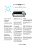
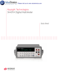
Agilent 34420A
nanoVolt/micro-Ohm meter
Data Sheet
• 7 1/2 digits resolution
Two Input Channels
Unequaled Versatility
• 100pv/100 nΩ sensitivity
An integral two-channel programmable
scanner simplifies voltage comparisons.
Built-in ratio and difference functions
enable automated two channel
measurements without the need for
an external nanoVolt scanner. Both
channels share the same low noise
specifications to ensure accurate
comparisons.
The 34420A gives you the versatility
to tackle your most challenging tasks,
both on the benchtop and in your
automated system. Standard features
include RS-232 and GPIB interfaces,
SCPI and Keithley 181 programming
language, 1024-reading memory,
scaling and statistics, and a chart
recorder analog output.
Built-In Resistance and
Temperature
Agilent IntuiLink:Easy Data Access
• 1.3 nVrms /8 nVpp noise
performance
• Built-in low noise 2 channel
scanner
• Direct SPRT, RTD, Thermistor, and
Thermocouple measurements
Nanovolt Performance
at a Microvolt Price
The Agilent Technologies 34420A
nanoVolt/micro-Ohm meter is a
high-sensitivity multimeter optimized
for performing low-level measurements. It combines low-noise voltage
measurements with resistance and
temperature functions, setting a
new standard in low-level flexibility
and performance.
Take the Uncertainty Out of Your
Low-Level Measurements
Low-noise input amplifiers and a
highly tuned input protection scheme
bring reading noise down to 8 nVpp.
Combine this with 71/2 digits of resolution, selectable analog and digital
filtering, 2 ppm basic 24-hour dcV
accuracy, and a shielded, copper pin
connector and you’ve got accurate,
repeatable measurements you can
count on.
The 34420A combines its low-noise
nanoVolt input circuits with a highstability current source to provide
precise low-level resistance measurements – no more hassling with the
cost and complexity of an external
current source. Three resistance
modes are included:
• Standard
• Low-power
• Voltage-limited for
dry-circuit testing
Offset compensation is also provided
to minimize thermal EMFs and
associated errors.
SPRT Measurements
Built-in ITS-90 conversion routines
accept the calibration coefficients
from your SPRT probe for direct
temperature measurement and conversion. Thermocouples, thermistors,
and RTDs are also supported.
The included Agilent IntuiLink
software allows your captured data
to be put to work easily, using PC
applications such as Microsoft Excel®
or Word® to analyze, interpret, display,
print, and document the data you get
from the 34420A. You can specify the
meter setup and take a single reading
or log data to the Excel spreadsheet
in specified time intervals. To find
out more about IntuiLink visit
www.agilent.com/find/intuilink
Quality You Can Count On
The 34420A gives you the quality and
reliability you expect from Agilent
Technologies. From the product’s
proven >150,000 hour Mean Time
Between Failure, to its standard
1-year warranty, Agilent stands
behind you to bring a new level of
confidence to your low-level
measurements.
Specifications
Accuracy Specifications ±(% of reading + % of range) 1
Function
Range2
dc Voltage
1.0000000 mV3
10.000000 mV3
100.00000 mV
1.0000000 V
10.000000 V
100.00000 V4
Resistance 5
1.0000000 Ω
10.000000 Ω
100.00000 Ω
1.0000000 KΩ
10.000000 KΩ
100.00000 KΩ
1.0000000 MΩ
Low Power
Resistance 5
Voltage Limited
Resistance 5, 6
24 Hour
23 °C ± 1 °C
90 Day
23 °C ± 5 °C
1 Year
23 °C ± 5 °C
Temperature
Coefficient
0 °C—18 °C
28 °C—55 °C
0.0025 + .0020
0.0025 + .0002
0.0015 + .0003
0.0010 + .0003
0.0002 + .0001
0.0010 + .0004
0.0040 + .0020
0.0040 + .0002
0.0030 + .0004
0.0025 + .0004
0.0020 + .0004
0.0025 + .0005
0.0050 + .0020
0.0050 + .0003
0.0040 + .0004
0.0035 + .0004
0.0030 + .0004
0.0035 + .0005
0.0004 + .0001
0.0004 + .0001
0.0004 + .00006
0.0004 + .00004
0.0001 + .00002
0.0004 + .00005
10 mA
10 mA
10 mA
1 mA
100 µA
10 µA
5 µA
0.0015 + .0002
0.0015 + .0002
0.0015 + .0002
0.0015 + .0002
0.0015 + .0002
0.0015 + .0003
0.0020 + .0003
0.0050 + .0002
0.0040 + .0002
0.0040 + .0002
0.0040 + .0002
0.0040 + .0002
0.0040 + .0004
0.0050 + .0004
0.0070 + .0002
0.0060 + .0002
0.0060 + .0002
0.0060 + .0002
0.0060 + .0002
0.0060 + .0004
0.0070 + .0004
0.0005 + .00002
0.0005 + .00001
0.0005 + .00001
0.0005 + .00001
0.0005 + .00001
0.0005 + .00002
0.0006 + .00003
1Ω
1Ω
10 Ω
100 Ω
1 KΩ
1 KΩ
1 KΩ
1.0000000 Ω
10.000000 Ω
100.00000 Ω
1.0000000 KΩ
10.000000 KΩ
100.00000 KΩ
1.0000000 MΩ
10 mA
10 mA
1 mA
100 µA
10 µA
5 µA
5 µA
0.0015 + .0002
0.0015 + .0002
0.0015 + .0002
0.0015 + .0002
0.0015 + .0004
0.0015 + .0012
0.0020 + .0003
0.0050 + .0002
0.0040 + .0002
0.0040 + .0002
0.0040 + .0002
0.0040 + .0004
0.0040 + .0015
0.0050 + .0004
0.0070 + .0002
0.0060 + .0002
0.0060 + .0002
0.0060 + .0002
0.0060 + .0004
0.0060 + .0015
0.0070 + .0004
0.0005 + .00002
0.0005 + .00001
0.0005 + .00001
0.0005 + .00001
0.0005 + .00001
0.0005 + .00003
0.0006 + .00003
1Ω
1Ω
10 Ω
100 Ω
1 KΩ
1 KΩ
1 KΩ
10.000000 Ω
100.00000 Ω
1 mA
100 µA
0.0020 + .0002
0.0025 + .0002
0.0050 + .0002
0.0050 + .0002
0.0070 + .0002
0.0070 + .0002
0.0005 + .00002
0.0005 + .00002
1Ω
5Ω
Channel 1 / Channel 2 (dcV Ratio)
Channel 1-Channel 2 (dcV Difference)
Temperature
SPRT 7
RTD
Thermistor
Thermocouple 8
Test Current
Ratio Error in % = Channel 1 accuracy in % + Channel 2 accuracy in %
Difference Error = Channel 1 (% of reading + % of range) + Channel 2 (% of reading + % of range)
(resolution = 0.001 °C)
SPRT Probe Accuracy + 0.003°C
RTD Probe Accuracy + 0.05°C
Thermistor Probe Accuracy + 0.1°C
Thermocouple Probe Accuracy + 0.2°C
DC Voltage Noise 9
Observation Period
Range
2-Minute
RMS
Noise
2-Minute
Peak-Peak
Noise
24-Hour
Peak-Peak
Noise
1 mV
10 mV
100 mV
1V
10 V
100 V
1.3 nVrms
1.5 nVrms
10 nVrms
100 nVrms
450 nVrms
11 µVrms
8 nVpp
10 nVpp
65 nVpp
650 nVpp
3 µVpp
75 µVpp
12 nVpp
14 nVpp
80 nVpp
800 nVpp
3.7 µVpp
90 µVpp
DC Voltage Noise vs Source Resistance 10
Source
Resistance
Noise
Analog
Filter
Digital
Filter
0
100
1k
10k
100k
1M
1.3 nVrms
1.7 nVrms
4 nVrms
13 nVrms
41 nVrms
90 nVrms
Off
Off
Off
Off
On
On
Med
Med
Med
Med
Med
Slow
2
Maximum
per Lead
Resistance
1 Specifications are for Channel 1 or Channel 2, after 2-hour warm-up, resolution
at 7.5 digits (100 NPLC), with FILTERS off. RESISTANCE specifications are for 4wire Ohms or 2-wire ohms using Null. Without Null, add 0.2 Ohms additional
error in 2-wire Ohms function. For Analog Filter ON, add 0.002% of reading.
2 20% overrange on all ranges except 5% on Voltage Limited Resistance.
3 After using Math Null. If Null is not used add 100 nanoVolts.
4 Channel 1 only.
5 Channel 1 only. Resistance measurements, for NPLC <1, add 160 µΩ rms noise.
6 Voltage limit can be set to 20 mV (default), 100 mV, or 500 mV. Measured
resistance plus Channel 1 HI and LO lead resistance is limited to 10.5 Ω on the
10 Ω range and 105 Ω on the 100 Ω range.
7 For 25Ω SPRT with triple-point of water check within the last 4 hours. With no
triple-point of water check, add 0.013°C for 24 hours, add 0.035°C for 90 day,
and add 0.55°C for 1 year specifications.
8 For fixed reference junction. Add 0.3˚C for external reference junction, add
2.0˚C for internal reference junction.
9 After a 2-hour warm-up, ± 1˚C, 6.5 digits (10 PLC) with Analog Filter Off and
Digital Filter Medium (50 reading average).
2-minute rms and 24-hour noise typical. For measurements using 0.02 or 0.2
NPLC, add 800 nV rms noise.
10 Typical noise behavior for Ch 1 or Ch 2, after 2 hour warm-up, 6.5 digits (10
PLC), 2 minute observation period on 1 mV range. For peak-to-peak noise, multiply rms noise by 6.
Measurement Characteristics
Operating Characteristics4
DC Voltage
Measurement Method:
Continuously integrating multi-slope III
A-D Converter
A-D Linearity:
0.00008% of reading + 0.00005% of range
Input Resistance:
100V (Ch1 only): 10 MΩ +- 1%
1mV through 10V: > 10 GΩ, in parallel with < 3.6 nF
Input Bias Current: <50 pA at 25 °C
Injected Current: <50 nA pp at 50 or 60 Hz
Input Protection:
150 V peak any input terminal
to Channel 1 LO, continuous
Channel-to-channel switching error (typical):
3 nV
Channel Isolation:
10
Isolation between input channels >10 Ω
Earth Isolation:
350 V peak any input terminal to earth.
Impedance from any input terminal to earth
is >10 GΩ and <400 pF
Maximum Voltage:
Channel 1 LO to Channel 2 LO, 150V peak
Function
Resistance
Measurement Method:
Selectable 4-wire or 2-wire ohms. Current
Source referenced to Channel 1 LO input
Offset Compensation:
Used on all ranges except 100 kΩ and 1 MΩ.
Can be turned off if desired
Protection: 150 V peak
Open Circuit Voltage:
For Resistance and Low Power Resistance
<14 V. 20 mV, 100 mV, 500 mV selectable clamp
Temperature
SPRT:
ITS-90 calibrated temperature with the range
of -190°C to +660°C
Thermocouple:
ITS-90 conversions of Type B, E, J, K, N, R, S, T
Thermistor: 5 kΩ
RTD: Type =.00385 and =.00392. R0 from
4.9 Ω to 2.1 kΩ. ITS -90 (IEC-751) Callendar
Van Dusen conversion.
Measurement Noise Rejection 60 (50) Hz1
dc CMRR: 140 dB
ac CMRR: 70 dB
Integration Time
200 plc/3.335 s (4 s)
100 plc/1.675 s (2 s)
20 plc/334 ms (400 ms)
10 plc/167 ms (200 ms)
2 plc/33.3 ms (40 ms)
1 plc/16.7 ms (20 ms)
<1 plc
Normal Mode
Rejection2
110 dB3
105 dB3
100 dB3
95 dB3
90 dB
60 dB
0
Digits
Integration Time
Readings/s 5
dcV
Thermocouple
71/2
71/2
61/2
61/2
51/2
51/2
41/2
200 plc
100 plc
20 plc
10 plc
1 plc
0.2 plc
0.02 plc
.15 (.125)
.3 (.25)
1.5 (1.25)
3 (2.5)
25 (20.8)
100 (100)
250 (250)
Resistance
dcV1/DCV2
dcV 1-2
RTD
Thermistor
0.2 plc
71/2
71/2
61/2
61/2
51/2
50 (50)
41/2
125 (125)
200 plc
100 plc
20 plc
10 plc
1 plc
.075 (.062)
.15 (.125)
.75 (.625)
1.5 (1.25)
12.5 (10.4)
0.02 plc
6
System Speeds
Chart Out (Analog Out)
Configuration Rates: 26/s to 50/s
Autorange Rate (Volts): >30/s
ASCII reading to RS-232: 55/s
ASCII reading to GPIB: 250/s
Max. Internal Trigger Rate: 250/s
Max. Ext. Trig. Rate to Memory: 250/s
Maximum output: ± 3V
Triggering and Memory
Span and Offset: Adjustable
Reading HOLD Sensitivity:
10%, 1%, 0.1%, or 0.01% of range
Samples/Trigger: 1 to 50,000
Trigger Delay: 0 to 3600 s; 10 µs step size
External Trigger Delay: <1 ms
External Trigger Jitter: <500 µs
Memory: 1024 readings
Standard Programming Languages
Math Functions
NULL (Channel 1 dcV, Channel 2 dcV, Difference,
Resistance, Temperature)
STATS (Min, Max, Average, Peak-Peak, Standard
Deviation, Number of readings)
SCALE (Allows linear scaling as y = mx+b)
CHART NULL (Establishes zero for rear panel
output)
Filter (Analog or Digital or Both)
Analog:
Low pass 2 pole @ 13Hz, available for dcV on
1 mV, 10 mV, 100 mV range
Digital:
Moving average filter, 10 (fast), 50 (medium),
or 100 (slow) reading averages.
1 For 1 kΩ unbalanced in LO lead.
2 For power line frequency ± - 0.1%, Filters OFF. For
Digital Filter slow add 20 db, for medium or fast add
10 db for NPLC ≥ 1.
3 For power line frequency ± - 1%, use 80 db, for ± 3% use 60 db.
4 Speeds are for delay 0, Display OFF, Filters OFF,
Offset Compensation OFF.
5 Reading speeds for 60 Hz or (50 Hz), 100 mV through
100 V ranges. 1 mV range 30/s MAX, 10 mV range
170/s MAX, thermocouple 120/s MAX.
6 Speeds are for NPLC 0.02, Delay 0, Display OFF,
Chart Out OFF.
Resolution: 16 bits
Accuracy: ± 0.1% of output + 1 mV
Output Resistance: 1 kΩ ± 5%
Update rate: once per reading
SCPI (IEEE 488.2), Keithley 181
Accessories Included
4 ft low thermal cable with copper spade lugs,
4-wire shorting plug, user’s manual, service manual, test report, contact cleaner, and power cord.
General Specifications
Front Panel Connection:
Shielded, low thermal, 99% copper contacts.
Power Supply:
100V/120V/220V(230V)/240V +- 10%.
Power Line Frequency:
45 Hz to 66 Hz and 360 Hz to 440 Hz.
Automatically sensed at power-on.
Power Consumption:
25VA peak (10W average).
Operating Environment:
Full accuracy for 0 °C to 55 °C. Full accuracy
to 80% R.H. up to 30 °C.
Storage Environment:
-40 °C to 75 °C.
Size: 254.4 mm W x 374.0 mm L x 103.6 mm H
(10.02” W x 14.72” L x 4.08” H)
Weight: 3 kg (6.5 lbs).
Safety:
Designed to CSA, UL-1244, IEC-1010.
RFI and ESD: CISPR 11.
3
Ordering Information
Agilent Technologies’ Test and Measurement
Support, Services, and Assistance
34420A nanoVolt/micro-Ohm meter
Agilent Technologies aims to maximize the value
you receive, while minimizing your risk and problems.
We strive to ensure that you get the test and
measurement capabilities you paid for and obtain
the support you need. Our extensive support
resources and services can help you choose the
right Agilent products for your applications and
apply them successfully. Every instrument and
system we sell has a global warranty. Two
concepts underlie Agilent's overall support policy:
"Our Promise" and "Your Advantage."
Includes low-thermal input cable (34102A),
low-thermal shorting plug (34103A), Kelvin
clip set (11062A), operating manual, service
manual, and quick reference guide, test
report with calibration sticker, 2.3 ml bottle
of contact cleaner, and power cord.
Options
34420A-1CM Rack mount kit
(P/N 5062-3972)
34420A-ABA English localization
34420A-ABD German localization:
translated operating manual
34420A-ABF French localization:
translated operating manual
34420A-ABJ Japanese localization:
translated operating manual
34420A-A6J ANSI Z540 compliant
calibration
Our Promise
Our Promise means your Agilent test and
measurement equipment will meet its advertised
performance and functionality. When you are
choosing new equipment, we will help you with
product information, including realistic performance
specifications and practical recommendations
from experienced test engineers. When you receive
your new Agilent equipment, we can help verify
that it works properly, and help with initial
product operation.
Your Advantage
Accessories
34102A Low-thermal input cable (fourconductor) with copper spade lugs
34103A Low-thermal shorting plug
34104A Low-thermal input connector
34161A Accessory pouch
Your Advantage means that Agilent offers a wide
range of additional expert test and measurement
services, which you can purchase according to your
unique technical and business needs. Solve
problems efficiently and gain a competitive edge by
contracting with us for calibration, extra-cost
upgrades, out-of-warranty repairs, and onsite
education and training, as well as design, system
integration, project management, and other
professional engineering services. Experienced
Agilent engineers and technicians worldwide can
help you maximize your productivity, optimize the
return on investment of your Agilent instruments
and systems, and obtain dependable measurement
accuracy for the life of those products.
Get assistance with all your test and measurement
needs at:
www.agilent.com/find/assist
Product specifications and descriptions in
this document subject to change without notice.
© Agilent Technologies, Inc. 1998, 2000, 2005
Printed in U.S.A. March 14, 2005
5968-0161EN