1
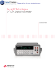
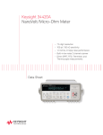
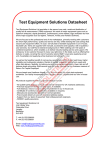
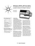
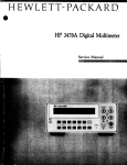
Agilent 34401A Multimeter
Uncompromising Performance
for Benchtop and System Testing
Product Overview
• Measure up to 1000 volts
with 6 1/2 digits resolution
• 0.0015% basic dcV
accuracy (24 hour)
• 0.06% basic acV
accuracy (1 year)
• 3 Hz to 300 kHz ac bandwidth
• 1000 readings/s direct to GPIB
Superior Performance
The Agilent Technologies 34401A
multimeter gives you the performance you need for fast, accurate
bench and system testing. The
34401A provides a combination of
resolution, accuracy and speed that
rivals DMMs costing many times
more. 61/2 digits of resolution,
0.0015% basic 24-hr dcV accuracy
and 1,000 readings/s direct to
GPIB assure you of results that
are accurate, fast, and repeatable.
Use It on Your Benchtop
The 34401A was designed with
your bench needs in mind.
Functions commonly associated
with bench operation, like continuity and diode test, are built in. A
Null feature allows you to remove
lead resistance and other fixed offsets in your measurements. Other
capabilities like min/max/avg
readouts and direct dB and dBm
measurements make checkout with
the 34401A faster and easier.
The 34401A gives you the ability to
store up to 512 readings in internal
memory. For trouble-shooting, a
reading hold feature lets you
concentrate on placing your test
leads without having to constantly
glance at the display.
Use It for Systems Testing
For systems use, the 34401A gives
you faster bus throughput than any
other DMM in its class. The 34401A
can send up to 1,000 readings/s
directly across GPIB in user-friendly
ASCII format.
You also get both GPIB and RS-232
interfaces as standard features.
Voltmeter Complete and External
Trigger signals are provided so you
can synchronize to other instruments
in your test system. In addition, a
TTL output indicates Pass/Fail
results when limit testing is used.
To ensure both forward and backward compatibility, the 34401A
includes three command languages
(SCPI, Agilent 3478A and Fluke
8840A /42A), so you don’t have to
rewrite your existing test software. An
optional rack mount kit is available.
Easy to Use
Commonly accessed attributes, such
as functions, ranges, and resolution
are selected with a single button press.
Advanced features are available
using menu functions that let you
optimize the 34401A for your
applications.
The included Agilent IntuiLink
software allows you to put your
captured data to work easily, using
PC applications such as Microsoft
Excel® or Word® to analyze, interpret, display, print, and document
the data you get from the 34401A.
You can specify the meter setup
and take a single reading or log
data to the Excel spreadsheet in
specified time intervals. Programmers can use ActiveX components
to control the DMM using SCPI
commands. To find out more
about IntuiLink, visit
www.agilent.com/find/intuilink
1-Year Warranty
With your 34401A, you get full
documentation, a high-quality test
lead set, calibration certificate with
test data, and a 1-year warranty,
all for one low price.
Accuracy Specifications ± (% of reading + % of range)1
Function
Range 3
dc voltage
100.0000 mV
1.000000 V
10.00000 V
100.0000 V
1000.000 V
True rms
ac voltage4
100.0000 mV
1.000000 V
to 750.000 V
Frequency,
etc.
24 Hour 2
23°C ±1°C
90 Day
23°C ±5°C
1 Year
23°C ±5°C
Temperature Coefficient
0°C to -18°C
28°C to -55°C
0.0030 + 0.0030
0.0020 + 0.0006
0.0015 + 0.0004
0.0020 + 0.0006
0.0020 + 0.0006
0.0040 + 0.0035
0.0030 + 0.0007
0.0020 + 0.0005
0.0035 + 0.0006
0.0035 + 0.0010
0.0050 + 0.0035
0.0040 + 0.0007
0.0035 + 0.0005
0.0045 + 0.0006
0.0045 + 0.0010
0.0005 + 0.0005
0.0005 + 0.0001
0.0005 + 0.0001
0.0005 + 0.0001
0.0005 + 0.0001
3 Hz – 5 Hz
5 Hz – 10 Hz
10 Hz – 20 kHz
20 kHz – 50 kHz
50 kHz – 100 kHz
100 kHz – 300 kHz6
1.00 + 0.03
0.35 + 0.03
0.04 + 0.03
0.10 + 0.05
0.55 + 0.08
4.00 + 0.50
1.00 + 0.04
0.35 + 0.04
0.05 + 0.04
0.11 + 0.05
0.60 + 0.08
4.00 + 0.50
1.00 + 0.04
0.35 + 0.04
0.06 + 0.04
0.12 + 0.04
0.60 + 0.08
4.00 + 0.50
0.100 + 0.004
0.035 + 0.004
0.005 + 0.004
0.011 + 0.005
0.060 + 0.008
0.20 + 0.02
3 Hz – 5 Hz
5 Hz –10 Hz
10 Hz – 20 kHz
20 kHz – 50 kHz
50 kHz – 100 kHz 5
100 kHz – 300 kHz 6
1.00 + 0.02
0.35 + 0.02
0.04 + 0.02
0.10 + 0.04
0.55 + 0.08
4.00 + 0.50
1.00 + 0.03
0.35 + 0.03
0.05 + 0.03
0.11 + 0.05
0.60 + 0.08
4.00 + 0.50
1.00 + 0.03
0.35 + 0.03
0.06 + 0.03
0.12 + 0.04
0.60 + 0.08
4.00 + 0.50
0.100 + 0.003
0.035 + 0.003
0.005 + 0.003
0.011 + 0.005
0.060 + 0.008
0.20 + 0.02
0.008 + 0.004
0.008 + 0.001
0.008 + 0.001
0.008 + 0.001
0.008 + 0.001
0.020 + 0.001
0.800 + 0.010
0.010 + 0.004
0.010 + 0.001
0.010 + 0.001
0.010 + 0.001
0.010 + 0.001
0.040 + 0.001
0.800 + 0.010
0.0006 + 0.0005
0.0006 + 0.0001
0.0006 + 0.0001
0.0006 + 0.0001
0.0010 + 0.0002
0.0030 + 0.0004
0.1500 + 0.0002
0.005 + 0.010
0.010 + 0.004
0.050 + 0.006
0.100 + 0.020
0.030 + 0.020
0.030 + 0.005
0.080 + 0.010
0.120 + 0.020
0.050 + 0.020
0.050 + 0.005
0.100 + 0.010
0.120 + 0.020
0.0020 + 0.0020
0.0020 + 0.0005
0.0050 + 0.0010
0.005 + 0.0020
Resistance 7
100.0000 Ω
1.000000 kΩ
10.00000 kΩ
100.0000 kΩ
1.000000 MΩ
10.00000 MΩ
100.0000 MΩ
dc current
10.00000 mA
100.0000 mA
1.000000 A
3.00000 A
True rms
ac current 4
1.000000 A
3 Hz – 5 Hz
5 Hz – 10 Hz
10 Hz – 5 kHz
1.00 + 0.04
0.30 + 0.04
0.10 + 0.04
1.00 + 0.04
0.30 + 0.04
0.10 + 0.04
1.00 + 0.04
0.30 + 0.04
0.10 + 0.04
0.100 + 0.006
0.035 + 0.006
0.015 + 0.006
3.00000 A
3 Hz – 5 Hz
5 Hz – 10 Hz
10 Hz – 5 kHz
1.10 + 0.06
0.35 + 0.06
0.15 + 0.06
1.10 + 0.06
0.35 + 0.06
0.15 + 0.06
1.10 + 0.06
0.35 + 0.06
0.15 + 0.06
0.100 + 0.006
0.035 + 0.006
0.015 + 0.006
Frequency
or period 8
100 mV to
750 V
3 Hz – 5 Hz
5 Hz – 10 Hz
10 Hz – 40 Hz
40 Hz – 300 kHz
0.10
0.05
0.03
0.006
0.10
0.05
0.03
0.01
0.10
0.05
0.03
0.01
0.005
0.005
0.001
0.001
Continuity
1000.0 Ω
1 mA test current
0.002 + 0.030
0.008 + 0.030
0.010 + 0.030
0.001 + 0.002
1.0000 V
1 mA test current
0.002 + 0.010
0.008 + 0.020
0.010 + 0.020
0.001 + 0.002
Diode test
1
2
3
4
5
6
7
8
9
9
1 mA Current Source 0.0030 + 0.0030
1 mA
0.0020 + 0.0005
100 µA
0.0020 + 0.0005
10 µA
0.0020 + 0.0005
5.0 µA
0.002 + 0.001
500 nA
0.015 + 0.001
500 nA || 10 MΩ
0.300 + 0.010
< 0.1 V Burden Voltage
< 0.6 V
< 1.0 V
< 2.0 V
Specifications are for 1 hr warm-up and 61 ⁄ 2 digits, slow ac filter.
Relative to calibration standards.
20% over range on all ranges except 1000 Vdc and 750 Vac ranges.
For sinewave input > 5% of range. For inputs from 1% to 5% of range
and < 50 kHz, add 0.1% of range additional error.
750 V range limited to 100 kHz or 8 x 10⁷ Volt-Hz.
Typically 30% of reading error at 1 MHz.
Specifications are for 4-wire ohms function or 2-wire ohms using Math Null.
Without Math Null, add 0.2 Ω additional error in 2-wire ohms function.
Input >100 mV. For 10 mV to 100 mV inputs multiply % of reading error x10.
Accuracy specifications are for the voltage measured at the input terminals
only. 1 mA test current is typical. Variation in the current source will create
some variation in the voltage drop across a diode junction.
103.6 mm
254.4 mm
374.0 mm
88.5 mm
212.6 mm
2
348.3 mm
Measurement Characteristics
dc Voltage
True RMS ac Current
Triggering and Memory
Measurement Method:
Continuously integrating multi-slope III
A-D converter
Measurement Method:
Directly coupled to the fuse and shunt.
ac coupled true rms measurement
(measures the ac component only).
Reading HOLD Sensitivity:
10%, 1%, 0.1%, or 0.01% of range
Shunt Resistance:
0.1 Ω for 1 A and 3 A ranges
Trigger Delay: 0 to 3600 s: 10 µs step size
Input Protection:
Externally accessible 3 A 250 V fuse
Internal 7 A 250 V fuse
External Trigger Jitter: < 500 µs
A-D Linearity:
0.0002% of reading + 0.0001% of range
Input Resistance:
10 MΩ or 0.1 V, 1 V, 10 V ranges:
Selectable > 10,000 MΩ
100 V, 1000 V ranges: 10 MΩ ±1%
Input Bias Current:
< 30 pA at 25°C
Input Protection: 1000 V all ranges
dcV:dcV ratio accuracy:
V input Accuracy + Vrelevance Accuracy
Frequency and Period
NULL, min/max/average, dBm, dB, limit test
(with TTL output)
Voltage Ranges:
Same as ac voltage function
Standard Programming Languages
Measurement Method:
AC-coupled true rms-measures the ac
component of the input with up to 400 Vdc
of bias on any range.
Continuity/Diode
Input Impedance:
1 MΩ ± 2% in parallel with 100 pF
Input Protection: 750 Vrms all ranges
Resistance
Measurement Method:
Selectable 4-wire or 2-wire Ohms.
Current source referenced to LO input.
Maximum Lead Resistance (4-wire):
10% of range per lead for 100 Ω, 1 kΩ ranges.
1 kΩ per lead on all other ranges.
Input Protection:
1000 V all ranges
Response Time:
300 samples/s with audible tone
Input Protection:
Externally accessible 3 A 250 V fuse
Internal 7 A 250 V fuse
SCPI (IEEE-488.2), Agilent 3478A,
Fluke 8840A/42A
Accessories Included
Test lead kit with probe, alligator
and grabber attachments
Continuity Threshold:
Selectable from 1 Ω to 1000 Ω
Operating manual, service manual,
test report and power cord
Measurement Noise Rejection 60 (50) Hz1
General Specifications
dc CMRR: 140 dB
ac CMRR: 70 dB
Power Supply:
100 V/120 V/220 V/240 V ±10%
Integration Time and
Normal Mode Rejection2
100 plc/1.67 s (2 s): 60 dB3
10 plc/167 ms (200 ms): 60 dB3
1 plc/16.7 ms (20 ms): 60 dB
<1 plc/3 ms or 800 µs): 0 dB
Operating Characteristics 4
Function
Digits
Reading/s
dcV, dcl, and
Resistance
6 1/2
6 1/2
5 1/2
5 1/2
4 1/2
6 1/2
6 1/2
6 1/2
6 1/2
6 1/2
5 1/2
4 1/2
0.6 (0.5)
6 (5)
60 (50)
300
1000
0.15 slow (3 Hz)
1 medium (20 Hz)
10 fast (200 Hz)
505
1
9.8
80
dc Current
Shunt Resistance:
5 Ω for 10 mA, 100 mA
0.1 Ω for 1 A, 3 A
Memory: 512 readings
Math Functions
Gate Time: 1 s, 100 ms, or 10 ms
Additional Crest Factor errors (non-sinewave):
Crest factor 1-2: 0.05% of reading
Crest factor 2-3: 0.15% of reading
Crest factor 3-4: 0.30% of reading
Crest factor 4-5: 0.40% of reading
External Trigger Delay: < 1 ms
Measurement Method:
Reciprocal counting technique
True RMS ac Voltage
Crest Factor:
Maximum of 5:1 at full scale.
Samples/Trigger:
1 to 50,000
acV, acl
Frequency
or Period
Power Line Frequency:
45 Hz to 66 Hz and 360 Hz to 440 Hz,
Automatically sensed at power-on
Power Consumption: 25 VA peak (10 W average)
Operating Environment:
Full accuracy for 0°C to 55°C,
Full accuracy to 80% R.H. at 40°C
Storage Temperature: -40°C to 70°C
Weight: 3.6 kg (8.0 lbs)
Safety: Designed to CSA, UL-1244, IEC-348
RFI and ESD:
MIL-461C, FTZ 1046, FCC
Vibration & Shock:
MIL-T-28800E, Type III, Class 5 (sine only)
Warranty: 1 year
1
2
3
Frequency and Period
Configuration rates:
Autorange rate (dc Volts):
ASCII readings to RS-232:
ASCII readings to RS-232:
Maximum internal trig rate:
Max. ext trig. rate to memory:
3
4
26/s to 50/s
>30/s
55/s
1000/s
1000/s
1000/s
5
6
For 1 kΩ unbalanced in LO lead,
± 500 V peak maximum.
For power line frequency ± 0.1%.
For power line frequency ± 0.1% use 40 dB
or ± 3% use 30 dB.
Reading speeds for 60 Hz and (50 Hz) operation.
Maximum useful limit with default settling
delays defeated.
Speeds are for 4 1 ⁄ 2 digits, delay 0, auto-zero
and display OFF.
Ordering Information
Agilent 34410A multimeter
accessories included:
Test lead kit with probe,
alligator, and grabber
attachments, operating
manual, service manual,
calibration certificate,
test report, and power cord.
Options
34401A-1CM
Rack mount kit*
(P/N 5063-9240)
34401A-OBO
DMM without manuals
34401A-A6J
ANSI Z540 compliant calibration
Manual Options
(Please specify one)
34401A-ABA
34401A-ABD
34401A-ABE
34401A-ABF
34401A-ABJ
34401A-ABZ
34401A-AB0
34401A-AB1
34401A-AB2
34401A-AKT
US English
German
Spanish
French
Japanese
Italian
Taiwan Chinese
Korean
Chinese
Russian
Agilent Accessories
11059A
11060A
11062A
34131
34161A
34171B
34172B
34330A
E2308A
Kelvin probe set
Surface mount device
(SMD) test probes
Kelvin clip set
Hard transit case
Accessory pouch
Input terminal connector
(sold in pairs)
Input calibration short
(sold in pairs)
30 A current shunt
5 k thermistor probe
* For racking two side-by-side,
order both items below:
Lock link kit (P/N 5061-9694)
Flange kit (P/N 5063-9212)
Remove all doubt
Our repair and calibration services
will get your equipment back to you,
performing like new, when promised. You will get full value out of
your Agilent equipment throughout its lifetime. Your equipment
will be serviced by Agilent-trained
technicians using the latest factory
calibration procedures, automated
repair diagnostics and genuine parts.
You will always have the utmost
confidence in your measurements.
Agilent offers a wide range of additional expert test and measurement services for your equipment,
including initial start-up assistance
onsite education and training, as well
as design, system integration, and
project management.
For more information on repair and
calibration services, go to:
www.agilent.com/find/removealldoubt
Agilent Email Updates
www.agilent.com/find/emailupdates
Get the latest information on the
products and applications you select.
Agilent Direct
www.agilent.com/find/agilentdirect
Quickly choose and use your test
equipment solutions with confidence.
Agilent
Open
www.agilent.com/find/open
Agilent Open simplifies the process
of connecting and programming
test systems to help engineers
design, validate and manufacture
electronic products. Agilent offers
open connectivity for a broad range
of system-ready instruments, open
industry software, PC-standard I/O
and global support, which are
combined to more easily integrate
test system development.
www.lxistandard.org
LXI is the LAN-based successor to
GPIB, providing faster, more efficient
connectivity. Agilent is a founding
member of the LXI consortium.
www.agilent.com
For more information on Agilent Technologies’
products, applications or services, please
contact your local Agilent office. The complete
list is available at:
www.agilent.com/find/contactus
Americas
Canada
Latin America
United States
(877) 894-4414
305 269 7500
(800) 829-4444
Asia Pacific
Australia
China
Hong Kong
India
Japan
Korea
Malaysia
Singapore
Taiwan
Thailand
1 800 629 485
800 810 0189
800 938 693
1 800 112 929
81 426 56 7832
080 769 0800
1 800 888 848
1 800 375 8100
0800 047 866
1 800 226 008
Europe
Austria
Belgium
Denmark
Finland
France
Germany
0820 87 44 11
32 (0) 2 404 93 40
45 70 13 15 15
358 (0) 10 855 2100
0825 010 700
01805 24 6333*
*0.14 /minute
Ireland
1890 924 204
Italy
39 02 92 60 8484
Netherlands
31 (0) 20 547 2111
Spain
34 (91) 631 3300
Sweden
0200-88 22 55
Switzerland (French) 41 (21) 8113811(Opt 2)
Switzerland (German) 0800 80 53 53 (Opt 1)
United Kingdom
44 (0) 118 9276201
Other European Countries:
www.agilent.com/find/contactus
Revised: May 7, 2007
Product specifications and descriptions
in this document subject to change
without notice.
© Agilent Technologies, Inc. 2007
Printed in USA, August 28, 2007
5968-0162EN