1
Freescale Semiconductor, Inc...
Freescale Semiconductor, Inc.
Internet Connectivity
with HCS12 16-bit
Microcontroller using
the ACP Reference
Design
Designer Reference
Manual
M68HC12
Microcontrollers
DRM049
Rev. 0, 09/2003
MOTOROLA.COM/SEMICONDUCTORS
For More Information On This Product,
Go to: www.freescale.com
Freescale Semiconductor, Inc...
Freescale Semiconductor, Inc.
For More Information On This Product,
Go to: www.freescale.com
Freescale Semiconductor, Inc.
Freescale Semiconductor, Inc...
Internet Connectivity with
HCS12 16-bit
Microcontroller using the
ACP Reference Design
Designer Reference Manual — Rev 0
by:
Dr. Gerald Kupris, Motorola SPS, Munich, Germany.
Harald Kreidl
Motorola SPS
Munich, Germany
Dirk Lill
Steinbeis-Transfer Centre Embedded Design and Networking
University of Cooperative Education
Loerrach, Germany
Prof. Dr.-Ing. Axel Sikora
Steinbeis-Transfer Centre Embedded Design and Networking
University of Cooperative Education
Loerrach, Germany
DRM049 — Rev 0
Designer Reference Manual
MOTOROLA
3
For More Information On This Product,
Go to: www.freescale.com
Freescale Semiconductor, Inc...
Freescale Semiconductor, Inc.
Designer Reference Manual
DRM049 — Rev 0
4
MOTOROLA
For More Information On This Product,
Go to: www.freescale.com
Freescale Semiconductor, Inc.
Designer Reference Manual — DRM049
List of Sections
Section 1. emBetter — A Short Overview . . . . . . . . . . . . 15
Freescale Semiconductor, Inc...
Section 2. Connecting Embedded Applications to the
Internet . . . . . . . . . . . . . . . . . . . . . . . . . . . . . . . . . . . . . . . . 19
Section 3. Basics of Implementation. . . . . . . . . . . . . . . . 33
Section 4. Design Techniques for emBetter . . . . . . . . . . 43
Section 5. Overall Implementation of emBetter . . . . . . . 49
Section 6. Layer Implementation of emBetter . . . . . . . . 63
Section 7. Test environment . . . . . . . . . . . . . . . . . . . . . 109
Section 8. Sources . . . . . . . . . . . . . . . . . . . . . . . . . . . . . 119
DRM049 — Rev 0
MOTOROLA
Designer Reference Manual
List of Sections
For More Information On This Product,
Go to: www.freescale.com
5
Freescale Semiconductor, Inc.
Freescale Semiconductor, Inc...
List of Sections
Designer Reference Manual
6
DRM049 — Rev 0
List of Sections
For More Information On This Product,
Go to: www.freescale.com
MOTOROLA
Freescale Semiconductor, Inc.
Designer Reference Manual — DRM049
Table of Contents
Freescale Semiconductor, Inc...
Section 1. emBetter — A Short Overview
1.1
Protocol Suite . . . . . . . . . . . . . . . . . . . . . . . . . . . . . . . . . . . . . .15
1.2
Target Platforms . . . . . . . . . . . . . . . . . . . . . . . . . . . . . . . . . . . .16
1.3
Portability . . . . . . . . . . . . . . . . . . . . . . . . . . . . . . . . . . . . . . . . .16
1.4
Modularity . . . . . . . . . . . . . . . . . . . . . . . . . . . . . . . . . . . . . . . . . 17
1.5
Scalability . . . . . . . . . . . . . . . . . . . . . . . . . . . . . . . . . . . . . . . . .17
1.6
Market positioning. . . . . . . . . . . . . . . . . . . . . . . . . . . . . . . . . . .17
Section 2. Connecting Embedded Applications to the
Internet
2.1
Status and Trends . . . . . . . . . . . . . . . . . . . . . . . . . . . . . . . . . .19
2.2
System Design . . . . . . . . . . . . . . . . . . . . . . . . . . . . . . . . . . . . . 21
2.3
Internet Connectivity . . . . . . . . . . . . . . . . . . . . . . . . . . . . . . . . . 21
Section 3. Basics of Implementation
3.1
Overview. . . . . . . . . . . . . . . . . . . . . . . . . . . . . . . . . . . . . . . . . .33
3.2
Packet Switching . . . . . . . . . . . . . . . . . . . . . . . . . . . . . . . . . . . 33
3.3
Layered Protocol Models . . . . . . . . . . . . . . . . . . . . . . . . . . . . . 34
3.4
Client/Server Model . . . . . . . . . . . . . . . . . . . . . . . . . . . . . . . . .39
3.5
Ports and Sockets. . . . . . . . . . . . . . . . . . . . . . . . . . . . . . . . . . .40
Section 4. Design Techniques for emBetter
4.1
Overview. . . . . . . . . . . . . . . . . . . . . . . . . . . . . . . . . . . . . . . . . .43
DRM049 — Rev 0
MOTOROLA
Designer Reference Manual
Table of Contents
For More Information On This Product,
Go to: www.freescale.com
7
Freescale Semiconductor, Inc.
Table of Contents
4.2
Zero-copy Approach . . . . . . . . . . . . . . . . . . . . . . . . . . . . . . . . . 43
4.3
Unified Protocol Interfaces . . . . . . . . . . . . . . . . . . . . . . . . . . . . 45
4.4
Socket Interfaces . . . . . . . . . . . . . . . . . . . . . . . . . . . . . . . . . . . 45
4.5
Callback Functions . . . . . . . . . . . . . . . . . . . . . . . . . . . . . . . . . . 46
4.6
Blocking . . . . . . . . . . . . . . . . . . . . . . . . . . . . . . . . . . . . . . . . . . 47
Freescale Semiconductor, Inc...
Section 5. Overall Implementation of emBetter
5.1
Overview. . . . . . . . . . . . . . . . . . . . . . . . . . . . . . . . . . . . . . . . . .49
5.2
Structure and Interfaces . . . . . . . . . . . . . . . . . . . . . . . . . . . . . .49
5.3
Exception Handling. . . . . . . . . . . . . . . . . . . . . . . . . . . . . . . . . . 55
5.4
Buffer Handling and Data Flow. . . . . . . . . . . . . . . . . . . . . . . . . 56
Section 6. Layer Implementation of emBetter
6.1
Introduction . . . . . . . . . . . . . . . . . . . . . . . . . . . . . . . . . . . . . . . . 63
6.2
Modem Communication . . . . . . . . . . . . . . . . . . . . . . . . . . . . . . 63
6.3
The Point to Point Protocol (PPP) . . . . . . . . . . . . . . . . . . . . . . 72
6.4
The Internet Protocol (IP) . . . . . . . . . . . . . . . . . . . . . . . . . . . . .80
6.5
The Internet Control Message Protocol (ICMP) . . . . . . . . . . . .83
6.6
Socket Interface . . . . . . . . . . . . . . . . . . . . . . . . . . . . . . . . . . . . 83
6.7
Hypertext Transfer Protocol . . . . . . . . . . . . . . . . . . . . . . . . . . .96
6.8
Handling of Web Pages . . . . . . . . . . . . . . . . . . . . . . . . . . . . . 100
6.9
Simple Mail Transfer Protocol. . . . . . . . . . . . . . . . . . . . . . . . . 102
6.10
UDP Applications . . . . . . . . . . . . . . . . . . . . . . . . . . . . . . . . . . 106
Section 7. Test environment
7.1
Alarm Control Panel Reference Design . . . . . . . . . . . . . . . . .109
7.2
Setup of the Demonstration and Development Environment . 109
Designer Reference Manual
8
DRM049 — Rev 0
Table of Contents
For More Information On This Product,
Go to: www.freescale.com
MOTOROLA
Freescale Semiconductor, Inc.
Table of Contents
7.3
Simulation environment . . . . . . . . . . . . . . . . . . . . . . . . . . . . . 112
Section 8. Sources
Web Resources . . . . . . . . . . . . . . . . . . . . . . . . . . . . . . . . . . . 119
8.2
Literature. . . . . . . . . . . . . . . . . . . . . . . . . . . . . . . . . . . . . . . . .120
Freescale Semiconductor, Inc...
8.1
DRM049 — Rev 0
MOTOROLA
Designer Reference Manual
Table of Contents
For More Information On This Product,
Go to: www.freescale.com
9
Freescale Semiconductor, Inc.
Freescale Semiconductor, Inc...
Table of Contents
Designer Reference Manual
10
DRM049 — Rev 0
Table of Contents
For More Information On This Product,
Go to: www.freescale.com
MOTOROLA
Freescale Semiconductor, Inc.
Designer Reference Manual — DRM049
List of Figures
Figure
Freescale Semiconductor, Inc...
1-1
2-1
2-2
2-3
2-4
2-5
2-6
2-7
3-1
3-2
3-3
3-4
3-5
3-6
4-1
4-2
5-1
5-2
5-3
5-4
5-5
5-6
5-7
6-1
6-2
Title
emBetter Protocol Suite . . . . . . . . . . . . . . . . . . . . . . . . . . . . . . 16
Architectures of Internet Connectivity . . . . . . . . . . . . . . . . . . . . 22
Direct Connectivity . . . . . . . . . . . . . . . . . . . . . . . . . . . . . . . . . .22
Gateway-based Connectivity with Internal Use of Internet
Protocols. . . . . . . . . . . . . . . . . . . . . . . . . . . . . . . . . . . . . . . . . .25
Gateway-based Connectivity with Internal Use of Non-internet
Protocols. . . . . . . . . . . . . . . . . . . . . . . . . . . . . . . . . . . . . . . . . .27
Dialup to an Internet Service Provider . . . . . . . . . . . . . . . . . . .28
Communication Initiation of the emBETTER Implementation. .28
ISP-based Connectivity with a Portal Server . . . . . . . . . . . . . . 29
ISO/OSI Communication Layer Protocol . . . . . . . . . . . . . . . . . 35
ISO-OSI Reference Model and TCP-IP Reference Model and
Protocols. . . . . . . . . . . . . . . . . . . . . . . . . . . . . . . . . . . . . . . . . .36
HTTP Packets Via a Serial Link Takes 51 Bytes Plus a Variable
HTTP Header . . . . . . . . . . . . . . . . . . . . . . . . . . . . . . . . . . . . . .37
The Information Flow in the Layered Model [9] . . . . . . . . . . . .38
Client/Server Model . . . . . . . . . . . . . . . . . . . . . . . . . . . . . . . . .39
Ports and Sockets for Concurrent Servers . . . . . . . . . . . . . . . .40
Management of Output Buffers. . . . . . . . . . . . . . . . . . . . . . . . . 44
Processing of Received Data Link Layer Packet . . . . . . . . . . .47
Folder Structure of the emBetter Protocol Suite . . . . . . . . . . . . 50
The Project Structure of the emBetter Protocol Suite. . . . . . . .51
Declaration of API Variables. . . . . . . . . . . . . . . . . . . . . . . . . . . 53
Main Software Interfaces . . . . . . . . . . . . . . . . . . . . . . . . . . . . . 54
Main Software Interfaces . . . . . . . . . . . . . . . . . . . . . . . . . . . . . 55
Example for Exception Handling. . . . . . . . . . . . . . . . . . . . . . . .56
Call Structure of Function ppp_entry . . . . . . . . . . . . . . . . . . . .58
The Modem Initialization Strings. . . . . . . . . . . . . . . . . . . . . . . .65
The Modem AT Commands . . . . . . . . . . . . . . . . . . . . . . . . . . .65
DRM049 — Rev 0
MOTOROLA
Page
Designer Reference Manual
List of Figures
For More Information On This Product,
Go to: www.freescale.com
11
Freescale Semiconductor, Inc.
List of Figures
Freescale Semiconductor, Inc...
6-3
6-4
6-5
6-6
6-7
6-8
6-9
6-10
6-11
6-12
6-13
6-14
6-15
6-16
6-17
6-18
6-19
6-20
6-21
6-22
6-23
7-1
7-2
7-3
7-4
7-5
7-6
7-7
The Modem State Machine. . . . . . . . . . . . . . . . . . . . . . . . . . . .66
The States for Modem Input Comparison. . . . . . . . . . . . . . . . .66
The Simplified PPP State Machine. . . . . . . . . . . . . . . . . . . . . .73
The Supported LCP Negotiation Frames . . . . . . . . . . . . . . . . . 75
Negotiation of IP Addresses with LCPC . . . . . . . . . . . . . . . . . . 77
Reading the PPPbuffer . . . . . . . . . . . . . . . . . . . . . . . . . . . . . . .80
emBetter Socket Structure . . . . . . . . . . . . . . . . . . . . . . . . . . . . 85
Design of a sockaddr Struct . . . . . . . . . . . . . . . . . . . . . . . . . . .86
UDP Data Storage . . . . . . . . . . . . . . . . . . . . . . . . . . . . . . . . . .87
Function Calls To When Sending UDP Datagrams . . . . . . . . . 88
The Possible States for TCP Sockets. . . . . . . . . . . . . . . . . . . . 90
TCP Segment Stored in st_buf[index].cData . . . . . . . . . . . . . . 93
Function Calls Caused by soc_write() . . . . . . . . . . . . . . . . . . .94
HTML Page Providing Static Content . . . . . . . . . . . . . . . . . . . . 97
Organization of HTML File Names and String Pointers . . . . . .98
Dynamic Content in an HTML Page . . . . . . . . . . . . . . . . . . . .100
HTTP Functions for Dynamic Content . . . . . . . . . . . . . . . . . .101
Function Template for Generating Dynamic Content . . . . . . .102
SMTP Communication Between Mail Client and Mail Server.104
Non-blocking Implementation of SMTP . . . . . . . . . . . . . . . . .105
Proprietary UDP Client Software . . . . . . . . . . . . . . . . . . . . . . 107
Test Environment for the emBetter Suite . . . . . . . . . . . . . . . . 110
Information Provided on Debug Interface . . . . . . . . . . . . . . . .111
Settings for the Terminal. . . . . . . . . . . . . . . . . . . . . . . . . . . . .114
Data in the Command Window . . . . . . . . . . . . . . . . . . . . . . . . 114
Metrowerks Inspector Component . . . . . . . . . . . . . . . . . . . . . 115
Profiler Window. . . . . . . . . . . . . . . . . . . . . . . . . . . . . . . . . . . .116
Code Coverage Information . . . . . . . . . . . . . . . . . . . . . . . . . .117
Designer Reference Manual
12
DRM049 — Rev 0
List of Figures
For More Information On This Product,
Go to: www.freescale.com
MOTOROLA
Freescale Semiconductor, Inc.
Designer Reference Manual — DRM049
List of Tables
Table
Freescale Semiconductor, Inc...
2-1
2-2
2-3
2-4
2-5
2-6
4-1
5-1
5-2
5-3
5-4
6-1
6-2
6-3
6-4
6-5
6-6
6-7
Title
SWOT Analysis of Direct Connectivity Without Internet
Protocols. . . . . . . . . . . . . . . . . . . . . . . . . . . . . . . . . . . . . . . . . .23
SWOT Analysis of Direct Connectivity Without Internet
Protocols. . . . . . . . . . . . . . . . . . . . . . . . . . . . . . . . . . . . . . . . . .24
SWOT Analysis of Gateway-based Connectivity With Internal
Use of Internet Protocol and Ethernet . . . . . . . . . . . . . . . . . . .26
SWOT Analysis of Gateway-based Connectivity With Internal
Use of Non-internet Protocols. . . . . . . . . . . . . . . . . . . . . . . . . . 27
SWOT Analysis of ISP-based Connectivity With Dialup. . . . . . 29
SWOT Analysis of ISP-based Connectivity With a
Portal Server. . . . . . . . . . . . . . . . . . . . . . . . . . . . . . . . . . . . . . . 30
BSD Socket Function Implementation in emBetter. . . . . . . . . .46
List of Compilation Units . . . . . . . . . . . . . . . . . . . . . . . . . . . . . .52
Overview of Buffer Variables . . . . . . . . . . . . . . . . . . . . . . . . . .57
Overview of Functions in buffer.c . . . . . . . . . . . . . . . . . . . . . . .59
Header and Data Location for the Different Protocols . . . . . . . 60
s12_sci.c Functions . . . . . . . . . . . . . . . . . . . . . . . . . . . . . . . . .69
physical.c Functions . . . . . . . . . . . . . . . . . . . . . . . . . . . . . . . . . 70
drv_modem.c Functions . . . . . . . . . . . . . . . . . . . . . . . . . . . . . .71
PPP Functions . . . . . . . . . . . . . . . . . . . . . . . . . . . . . . . . . . . . . 77
Constant Values in IP Header . . . . . . . . . . . . . . . . . . . . . . . . .82
Header Fields Used for TCP Segment Processing . . . . . . . . . 89
Socket Values for TCP and IP Header . . . . . . . . . . . . . . . . . . . 94
DRM049 — Rev 0
MOTOROLA
Page
Designer Reference Manual
List of Tables
For More Information On This Product,
Go to: www.freescale.com
13
Freescale Semiconductor, Inc.
Freescale Semiconductor, Inc...
List of Tables
Designer Reference Manual
14
DRM049 — Rev 0
List of Tables
For More Information On This Product,
Go to: www.freescale.com
MOTOROLA
Freescale Semiconductor, Inc.
Designer Reference Manual — DRM049
Section 1. emBetter — A Short Overview
1.1 Protocol Suite
Freescale Semiconductor, Inc...
The emBetter protocol suite contains the following modules (see Figure
1-1. emBetter Protocol Suite):
Application layer
•
HTTP-web server (also for dialup)
•
TFTP file server
•
SMTP mail client
•
UDP-Client for portal-based solutions
Transport Layer
•
Transport Control Protocol (TCP)
•
User Datagram Protocol (UDP)
Network Layer
•
Internet Protocol (IP)
•
Internet Control Message Protocol (ICMP)
Net-to-Host-Layer
•
Point-to-Point-Protocol (PPP)
•
Generic modem drivers
•
Ethernet controller drivers (for Crystal CS8900)
•
Address Resolution Protocol (ARP)
DRM049 — Rev 0
MOTOROLA
Designer Reference Manual
emBetter — A Short Overview
For More Information On This Product,
Go to: www.freescale.com
15
Freescale Semiconductor, Inc...
Freescale Semiconductor, Inc.
HTTP
server
internet connectivity
web and other services
emBetter — A Short Overview
SMTP
client
proprietary
UDP
client
TFTP
server
socket interface
TCP
UDP
IP
ICMP
net-to-host layer interface
PPP
Ethernet
modem
hardware
ARP
Figure 1-1. emBetter Protocol Suite
1.2 Target Platforms
The emBetter protocol suite is optimized for use in 8- and 16-bit
microcontrollers and is an efficient platform for internet connectivity in
modular systems. The original implementation was done for a Motorola
HCS12-microcontroller under Metrowerks CodeWarrior V3.0.
1.3 Portability
The use of pure ANSI-C and a minimum of external library functions
make the emBetter protocol suite extremely portable to a variety of other
compilers and microcontrollers. The fitting to the hardware is performed
in one C- and one header-file, leading to a smooth design flow.
Adaption to the different instruction sets of modems is being done in a
single header file.
The PPP parts of the protocol suite were tested with the German internet
service providers (ISP) arcor [w1] and freenet [w3]. The connectivity with
telephone based dial-in was done with PCs running Microsoft Windows
98 and Windows 2000.
Designer Reference Manual
16
DRM049 — Rev 0
emBetter — A Short Overview
For More Information On This Product,
Go to: www.freescale.com
MOTOROLA
Freescale Semiconductor, Inc...
Freescale Semiconductor, Inc.
emBetter — A Short Overview
Modularity
1.4 Modularity
The modules of the emBetter protocol suite run as independent as the
protocol definition allow. The interfaces between the protocol layers
follow the common winsock standard (init, open, close, read, write).
Other physical layers, for example CAN or LIN, can be supported. On the
higher layers, additional protocols, such as Domain Name Service or
IPsec are under development. In case that a less performing target
hardware is being used, the protocols and functions can be switched off
before compilation. This holds true for add-in protocols, such as ICMP or
SMTP.
1.5 Scalability
Moreover, buffer and memory sizes can be scaled for optimal use of
resources and full scalability. All parameters are described in the text
files of the project.
However, in the pre-defined version, the emBetter protocol suite shows
extremely small code and memory size at a reasonable performance.
1.6 Market positioning
In order to push its availability in the market, emBetter is distributed as
an open-source product. However, this applies only for the application in
the alarm control panel reference design (ACPRD).
For additional features and integration of customer's application, support
is performed by Steinbeis Transfer Centre for Embedded Design and
Networking (STZEDN) [w3], a Design Alliance Partner of Motorola Inc.
DRM049 — Rev 0
MOTOROLA
Designer Reference Manual
emBetter — A Short Overview
For More Information On This Product,
Go to: www.freescale.com
17
Freescale Semiconductor, Inc.
Freescale Semiconductor, Inc...
emBetter — A Short Overview
Designer Reference Manual
18
DRM049 — Rev 0
emBetter — A Short Overview
For More Information On This Product,
Go to: www.freescale.com
MOTOROLA
Freescale Semiconductor, Inc...
Freescale Semiconductor, Inc.
Designer Reference Manual — DRM049
Section 2. Connecting Embedded Applications to the
Internet
2.1 Status and Trends
Remote maintenance and control is already widely used in industrial
automation and building automation and gains acceptance for many
other applications, for example smart home appliances, consumer
electronics, networking devices. Internet- and web-based connectivity is
playing a major part in unifying network infrastructure and company
information flow. It is a main stepping stone on the way to ubiquitous
computing [6].
Where the Internet may have been a dedicated network for computer
data exchange in its infant years, today, more and more small, non-PC
based, intelligent “machines” are connected to the Network of Networks.
The prognosis is that by 2005, the amount of non-PC users on the
Internet will far exceed the amount of PCs! For embedded internet
connectivity, various trends can be observed:
2.1.1 Maturing the Products
The market for embedded internet is maturing rapidly. Being a research
driven discipline for quite a while, internet protocol suites for embedded
systems are widely available as stand-alone software packets or
included in real-time operating systems. They are widely deployed and
reliable. Performance is increased and cost is reduced as
semiconductor device dimensions continue to scale.
2.1.2 Maturing the Market
The market for embedded internet is rapidly following the technical
advances. Maturity of the market can be identified by a broad variety of
products and solutions, as well as by a fine differentiation of market
DRM049 — Rev 0
MOTOROLA
Designer Reference Manual
Connecting Embedded Applications to the Internet
For More Information On This Product,
Go to: www.freescale.com
19
Freescale Semiconductor, Inc...
Freescale Semiconductor, Inc.
Connecting Embedded Applications to the Internet
players. However, this makes markets more complicated and inter
operability is at stake.
2.1.3 Embedding and Unifying Internet Connectivity and Web Services
Internet-connectivity gives access to a ubiquitous network of highest
availability and reasonable performance at lowest cost. This especially
holds true for target-oriented microcontroller-based embedded systems.
However, connectivity infrastructure is only the starting point for inter
operability and portability. A unified approach at application level (OSI
level 7) is the next step. Its broad acceptance in the office and
infotainment world, its flexible design and its efficient implementation
makes Hypertext Transfer Protocol (HTTP) the main contender for
automation and control.
2.1.4 Breaking the Embedded Isolation
Inter operability is even more questioned against the background of
traditional dedication of embedded solutions, when optimized software
hardware co-design and cost efficiency play a major role.
However, embedded internet calls for open systems and comprehensive
inter operability through all levels of communication models. A unified
data flow from enterprise resource planning (ERP) and management
information systems (MIS) to production planning systems (PPS) and
field control is envisaged.
2.1.5 Leveraging Security
If security is of high value for desktop computing, this holds true for
embedded computing, where production facilities and other hardware
equipment is at risk. Therefore, security has to be at its maximum.
Designer Reference Manual
20
DRM049 — Rev 0
Connecting Embedded Applications to the Internet
For More Information On This Product,
Go to: www.freescale.com
MOTOROLA
Freescale Semiconductor, Inc...
Freescale Semiconductor, Inc.
Connecting Embedded Applications to the Internet
System Design
2.2 System Design
A typical embedded internet device- may it be a highly integrated
microcontroller (µC) or a digital signal processor (DSP) - must handle at
least two tasks.
•
It has to control the system, it is embedded in. This functionality
often requires real-time operation of the device.
•
It has to provide the internet connectivity. Therefore, a TCP/IP
protocol suite has to run on the device.
This protocol usually requires a powerful processor, a complete
operating system and a large amount of memory to function. Depending
on the target hardware as well as the complexity of the problem, the
developer has to decide whether to use an operating system. According
to market analysis, more than 75% of the Embedded Applications use
operating system (OS). This OS may be proprietary, free or commercial.
At the time being, only few OS provide a TCP/IP protocol suite.
However, an 8 or 16 Bit Microcontroller may not have enough resources
for the implementation of an operating system. No OS applications can
be found in less complex applications often using small microcontrollers
with strict hardware and runtime restrictions. The choice of writing
standalone code is often made in order to optimize memory usage, code
size and run-time behavior. Since it is written as target specific code it is
often not portable to other targets.
2.3 Internet Connectivity
2.3.1 Overview
There is a good number of techniques, how to connect devices to the
internet [7]. The presented solutions (see Figure 1-1. emBetter
Protocol Suite) concern the overall architecture at data link and
networking layer, but do not consider the physical layer. Depending on
the implementation, the embedded device acts as client, who connects
to a server when an event occurs, or it is a server that is called by remote
DRM049 — Rev 0
MOTOROLA
Designer Reference Manual
Connecting Embedded Applications to the Internet
For More Information On This Product,
Go to: www.freescale.com
21
Freescale Semiconductor, Inc...
Freescale Semiconductor, Inc.
Connecting Embedded Applications to the Internet
devices in order to read the data stored by the device or to change the
settings of the device.
embedded internet application
c
non
internet
protocol
based
ISP-based
connectivity via
internet
gateway connectivity
via internet
direct connectivity
internet
d
protocol
based via
serial line
(SLIP/PP
P)
einternal
use of
noninternet
protocols
f
internal
use of
internet
protocols
fa
with IPmasquerading
g
direct dialup
h
dial-up via
portal
server
fbwithout
IPmasquerading
Figure 2-1. Architectures of Internet Connectivity
2.3.2 Direct Connectivity
µC
Remote Host
Modem µC
Modem PC
Figure 2-2. Direct Connectivity
In this solution (case 1 in Figure 2-1. Architectures of Internet
Connectivity and Figure 2-2. Direct Connectivity), both
communication end-points are directly connected via a telephone line. In
most cases, the microcontroller acts as web server and the host
computer dials to the embedded device. There are only rare cases,
where the embedded device dials to the remote server. However, client
connections in the presented way are comfortable for debugging
purpose, but for runtime conditions, such a client is nearly not to be seen.
Designer Reference Manual
22
DRM049 — Rev 0
Connecting Embedded Applications to the Internet
For More Information On This Product,
Go to: www.freescale.com
MOTOROLA
Freescale Semiconductor, Inc.
Connecting Embedded Applications to the Internet
Internet Connectivity
In most cases of direct connectivity, there is no advantage in using
standardized internet protocols and most systems work with proprietary
protocols with minimum overhead. So, in proper wording, this is no
internet connectivity (Table 2-1. SWOT Analysis of Direct
Connectivity Without Internet Protocols).
Freescale Semiconductor, Inc...
However, the use of internet protocol (case 2 in Figure
2-1. Architectures of Internet Connectivity), brings standardization
with it. This allows the use of internet based development and
application tools. The simplest implementation of internet connectivity is
based on serial line protocols, such as SLIP [ref] or PPP [ref]. Basic
implementations are well possible with 8 Bit microcontrollers (Table
2-2. SWOT Analysis of Direct Connectivity Without Internet
Protocols).
Table 2-1. SWOT Analysis of Direct Connectivity Without Internet
Protocols
Strength
Weakness
•
Simple to implement and debug
•
Alert function nearly impossible
•
High security by unknown
“address”
•
No simultaneous connections
•
Simple connection via µCs SCI
Opportunity
•
No costs for Internet Service
Provider
Threat
•
No use of the Internet
•
Only simultaneous technology
transfer of the two hosts possible
DRM049 — Rev 0
MOTOROLA
Designer Reference Manual
Connecting Embedded Applications to the Internet
For More Information On This Product,
Go to: www.freescale.com
23
Freescale Semiconductor, Inc...
Freescale Semiconductor, Inc.
Connecting Embedded Applications to the Internet
Table 2-2. SWOT Analysis of Direct Connectivity Without Internet
Protocols
Strength
Weakness
•
Simple to implement and debug
•
Additional protocol overhead
•
High security by unknown
“address”
•
Matching connection standards
necessary
•
Simple connection via µCs SCI
•
Alert function nearly impossible
•
Use of internet based
development and application
tools
•
No simultaneous connections
Opportunity
•
No costs for Internet Service
Provider
Threat
•
No use of the Internet, just the
same tools
•
Only simultaneous technology
transfer of the two hosts possible
2.3.3 Gateway-based Connectivity Via Internet
2.3.3.1 Overview
Internet connectivity using a gateway for the connection is very suitable
for smaller devices, because a part of the functionality can be extended
to this more powerful computer. Doing so allows the step-by-step
implementation of the necessary protocols on the embedded device up
to the final release. There are two possibilities for internal networking,
either IP-conformant or other protocols.
2.3.3.2 Internal use of internet protocols
The use of TCP/IP protocols on the microcontroller side allows for
highest flexibility and portability. However, additional protocol overhead
in the microcontroller is required. In most cases, Ethernet is used as
layer-2-protocol, because its interworking with TCP/IP is proven, for
example ARP, and because frame sizes show a good match.
Nevertheless, the use of other protocols, such as CAN for industrial
automation or LIN for home and facility automation, is well possible.
Designer Reference Manual
24
DRM049 — Rev 0
Connecting Embedded Applications to the Internet
For More Information On This Product,
Go to: www.freescale.com
MOTOROLA
Freescale Semiconductor, Inc.
Connecting Embedded Applications to the Internet
Internet Connectivity
µC
µC
µC
Gateway
Internet
Bus: CAN, LIN, I²C...
Configuring
Computer
Ethernet
Freescale Semiconductor, Inc...
Figure 2-3. Gateway-based Connectivity with Internal Use of
Internet Protocols
The gateway itself may be PC with routing-software, a fully-fledged
stand-alone router, or another embedded device implementing a routing
engine.
However, the internal use of internet protocols comes with two flavors:
•
If the gateway is just doing the routing, the IP addresses of the
microcontrollers are visible from the public internet. Thus,
embedded web-servers may easily be run. However, the devices
are prone to attacks from the internet.
•
In the second case, the gateway is a router, who runs Network
Address Translation (NAT) or IP-masquerading. In most
implementations, NAT works only for clients behind the gateway.
Then, no servers may be accessible from the outside. However,
this is not a matter of principle. IP-masquerading may saves costly
internet addresses and leverage security, as it is only the
gateway's IP-address, which is visible in the public internet.
DRM049 — Rev 0
MOTOROLA
Designer Reference Manual
Connecting Embedded Applications to the Internet
For More Information On This Product,
Go to: www.freescale.com
25
Freescale Semiconductor, Inc...
Freescale Semiconductor, Inc.
Connecting Embedded Applications to the Internet
Table 2-3. SWOT Analysis of Gateway-based Connectivity With
Internal Use of Internet Protocol and Ethernet
Strength
Weakness
•
Known Technology (CS 8900)
•
•
Fast data transfer compared to
modem
Ethernet uncommon in home
appliances
•
Dependence on gateway (single
point of failure
•
Multiple access to
microcontroller
Opportunity
•
Security options may be
extended to more powerful
gateway (firewall,
IP-masquerading)
•
Independent from remote host's
hardware
Threat
•
Prone to hacking,
2.3.3.3 Internal use of non-internet protocols
A good number of implementations let the microcontroller communicate
with a non-IP protocol. In many cases it is a simple serial protocol, and
in very many cases it is proprietary. In those cases, the embedded
devices can only communicate via internet with the appropriate gateway.
The gateway itself implements the server, but gathers information from
the embedded devices behind. The main advantage is that only the
gateway has to implement internet protocols. All embedded devices
behind the gateway may run an easier protocol. Consequently, this
solution is advantageous, when a significant number of low-end
embedded devices have to be connected to the internet.
Designer Reference Manual
26
DRM049 — Rev 0
Connecting Embedded Applications to the Internet
For More Information On This Product,
Go to: www.freescale.com
MOTOROLA
Freescale Semiconductor, Inc.
Connecting Embedded Applications to the Internet
Internet Connectivity
µC
µC
µC
Gateway
Internet
Proprietary Protocol
Remote Host
Ethernet
Freescale Semiconductor, Inc...
Figure 2-4. Gateway-based Connectivity with Internal Use of
Non-internet Protocols
Table 2-4. SWOT Analysis of Gateway-based Connectivity With
Internal Use of Non-internet Protocols
Strength
•
Cheap and easy access to
microcontroller
Weakness
•
Closed system of embedded
device and gateway
•
Dependence on gateway (single
point of failure
Opportunity
•
Web Server functionality runs on
powerful gateway
•
Security options may be
extended to more powerful
gateway (firewall,
IP-masquerading)
•
Independent from remote host's
hardware
Threat
•
Lack of portability
2.3.4 ISP-based Connectivity
2.3.4.1 Overview
Internet service providers play a major role in the architecture of the
public internet. The do not only proved the access to dialup hosts, but
also provide IP addresses and DNS-support. They may offer additional
services, such as web-server capabilities.
DRM049 — Rev 0
MOTOROLA
Designer Reference Manual
Connecting Embedded Applications to the Internet
For More Information On This Product,
Go to: www.freescale.com
27
Freescale Semiconductor, Inc.
Connecting Embedded Applications to the Internet
2.3.4.2 Dialup to an Internet Service Provider
µC
Internet Service Provider
Modem µC
Remote Host
Modem bank ISP
Internet
Freescale Semiconductor, Inc...
Ethernet
Figure 2-5. Dialup to an Internet Service Provider
The dialup connection is most common for client applications, for
example web-clients in the home-office. In this case, the IP address is
assigned by the ISP.
However, it is also possible to run a web-server via a dialup line and an
ISP. The main challenge is that the web-server has to dialup himself to
the ISP. The ISP does not provide the functionality to connect to one of
its customers. Additionally, the web-server does not have a fixed IP
address.
The remote host shall be able to initiate the dialup process, and
afterwards, the microcontroller has to communicate its IP address to a
connecting host. The necessary steps are shown in Figure
2-6. Communication Initiation of the emBETTER Implementation.
(1) Remote
activation of the
microcontroller
(2) Microcontroller
connects to the
ISP
(3) Negotiation of
the Internet
connection
(4) Sending of a
memo to user
containing IP
(5) User clicks
on the link in the
memo
(6) User
connected to the
microcontroller
Figure 2-6. Communication Initiation of the emBETTER Implementation
There are two possibilities for the activation of the microcontroller ((1) of
Figure 2-6. Communication Initiation of the emBETTER
Implementation):
Designer Reference Manual
28
DRM049 — Rev 0
Connecting Embedded Applications to the Internet
For More Information On This Product,
Go to: www.freescale.com
MOTOROLA
Freescale Semiconductor, Inc...
Freescale Semiconductor, Inc.
Connecting Embedded Applications to the Internet
Internet Connectivity
•
It might be an incoming call on the modem's extension. This call is
not answered by the modem, but initiates the dialup to the
predefined extension number of the ISP.
•
A signal on one of the microcontroller's digital ports may serve as
an alarm to initiate the dialup.
Table 2-5. SWOT Analysis of ISP-based Connectivity With Dialup
Strength
•
ISP offers web services
(Mail-access…)
•
Microcontroller only online after
dialup (security against hacking)
Weakness
•
ISP has to assign a static IP (or
further solution for telling address
to host)
Opportunity
•
Alert function likely to be
implemented
•
Independent from remote host's
hardware
•
Independence from different ISP
Threat
•
ISP might change dialup
•
In times of heavy traffic, fail of
connection possible
2.3.4.3 ISP-based connectivity with a Portal Server
µC
Modem µC
ISP
Portal server
Remote Host
Modem bank ISP
Internet
Figure 2-7. ISP-based Connectivity with a Portal Server
The use of a portal server can be understood as a dual server
architecture. In Figure 2-7. ISP-based Connectivity with a Portal
Server, several embedded web servers are connected to the Internet,
DRM049 — Rev 0
MOTOROLA
Designer Reference Manual
Connecting Embedded Applications to the Internet
For More Information On This Product,
Go to: www.freescale.com
29
Freescale Semiconductor, Inc...
Freescale Semiconductor, Inc.
Connecting Embedded Applications to the Internet
and controlled by an application server. The remote host connects to the
application server, which presents a user interface. The dynamic data for
this interface are retrieved from the embedded devices. The use of a
portal server gives highest flexibility, best performance and highest
portability. Additionally, it might be the basis for a VPI-conformant
architecture [w10]. All services between host computer and portal server
and between portal server and embedded device should be run over
HTTP.
Table 2-6. SWOT Analysis of ISP-based Connectivity With a Portal
Server
Strength
•
Web services from the ISP
•
Microcontroller only online after
dialup
•
User interface on portal possible
Weakness
•
ISP has to call back the
microcontroller
Opportunity
Threat
•
Alert may be interpreted by portal
•
ISP might change dialup
•
Independent from remote host's
hardware
•
Dependence on portal server
and ISP, if not properly designed
•
Host authentication performable
by portal
•
High availability through
redundancy
2.3.5 Conclusion
The SWOT-analyses in this chapter demonstrates that there is no ideal
general internet connectivity for embedded devices. The best solution
strongly depends on the actual circumstances. This makes it an
important challenge for a TCP/IP protocol suite such as emBetter, to
provide a set of module, which can be adapted to a maximum number of
use cases.
The released version 1.1 of emBetter with ACPRD, corresponds to case
5 in Figure 2-1. Architectures of Internet Connectivity. However,
Designer Reference Manual
30
DRM049 — Rev 0
Connecting Embedded Applications to the Internet
For More Information On This Product,
Go to: www.freescale.com
MOTOROLA
Freescale Semiconductor, Inc.
Connecting Embedded Applications to the Internet
Internet Connectivity
additional modules are available at STZEDN [w2] to cover other used
cases.
The inclusion of Ethernet-module leads to case 4 in Figure
2-1. Architectures of Internet Connectivity.
•
A VPI-compliant portal-server [w10] corresponds to case 6 in
Figure 2-1. Architectures of Internet Connectivity.
Freescale Semiconductor, Inc...
•
DRM049 — Rev 0
MOTOROLA
Designer Reference Manual
Connecting Embedded Applications to the Internet
For More Information On This Product,
Go to: www.freescale.com
31
Freescale Semiconductor, Inc.
Freescale Semiconductor, Inc...
Connecting Embedded Applications to the Internet
Designer Reference Manual
32
DRM049 — Rev 0
Connecting Embedded Applications to the Internet
For More Information On This Product,
Go to: www.freescale.com
MOTOROLA
Freescale Semiconductor, Inc...
Freescale Semiconductor, Inc.
Designer Reference Manual — DRM049
Section 3. Basics of Implementation
3.1 Overview
Three overall paradigms influence the implementation of embedded
internet connectivity:
•
The distribution of information into separate packets which travel
independently from source to destination is called packet
switching.
•
The modularity of a layered protocol stack sets high requirements
on the efficient realization of each layer and the interfaces in
between.
•
The client/server model implies an asymmetric communication
flow with the overall capability of being reached for servers.
3.2 Packet Switching
An important side of the Internet communication is the fact that the
information does not travel in a continuous stream, but in the form of
small data packets.
A packet is an information unit whose source and destination are
network-layer entities. A packet is composed of the network-layer
header and possibly a trailer and upper-layer data. The header and
trailer contain control information intended for the network-layer entity in
the destination system. Data from upper-layer entities is encapsulated in
the network-layer and trailer. The advantage of this packet technology is
that every packet travels independently from the others. This makes the
whole information transfer resistant against transmission failures. Also,
the system bandwidth is used very effectively.
DRM049 — Rev 0
MOTOROLA
Designer Reference Manual
Basics of Implementation
For More Information On This Product,
Go to: www.freescale.com
33
Freescale Semiconductor, Inc...
Freescale Semiconductor, Inc.
Basics of Implementation
A disadvantage of this technology is the fact, that control information has
to be added to each and every packet. Together with the layered
protocol stack, being described below, each protocol layer adds
information to the data packet. Therefore, it is not very efficient to submit
just a small piece of information, because the overhead generated by the
various protocols can be much larger than the transmitted data itself.
3.3 Layered Protocol Models
3.3.1 The OSI/ISO Reference Model and the TCP/IP Implementation
The Internet is a collection of individual networks, connected by
intermediate networking devices, that functions as a single large
network. The challenge when connecting various systems is to support
communication between disparate technologies. Different sites, for
example, may use different types of media, or they might operate at
varying speeds. A network management must provide centralized
support and troubleshooting capabilities. Configuration, security,
performance, and other issues must be adequately addressed for the
inter-network to function smoothly.
The Open Systems Interconnect (OSI) reference model which was
introduced in the seventies and released 1984 describes how
information from a software application in one node moves through a
network medium to a software application in another node (Figure
3-1. ISO/OSI Communication Layer Protocol).
Designer Reference Manual
34
DRM049 — Rev 0
Basics of Implementation
For More Information On This Product,
Go to: www.freescale.com
MOTOROLA
Freescale Semiconductor, Inc.
Basics of Implementation
Layered Protocol Models
user data
layer 7
Host A
Application
definition of the services provided by the
communication partner for each individual
application program
definition of the structures for user data with
regard to formatting
Freescale Semiconductor, Inc...
layer 2
Data Link
Session
layer 4
Transport
layer 3
Definition of a path from end-to-end; routing
addressing
ensuring correct data stream from point-topoint by definition of a data format for
channel coding; medium access control
Network
layer 2
Data Link
layer 1
layer 1
Physical
Presentation
control of data stream by providing errorfree logical channels
layer 3
Network
Application
creation and removal of logical channels in
physical transport systems
layer 4
Transport
user data
layer 5
layer 5
Session
Host B
layer 6
layer 6
Presentation
layer 7
definition of mechanical and electrical
properties of the transport medium
logical data flow
Physical
physical data flow
Figure 3-1. ISO/OSI Communication Layer Protocol
The OSI reference model is a conceptual model composed of seven
layers, each specifying particular network functions. It is now considered
the primary architectural model for inter-device communications.
The OSI model provides a conceptual framework for communications
between computers, but the model itself is not a method of
communication. Actual communication is made possible by using
communication protocols. The protocol is a formal set of rules and
conventions that governs how nodes exchange information over a
network medium.
Used protocols in the Internet are: the Internet Protocol (IP) with the
Internet Control Message Protocol (ICMP), the Transfer Control Protocol
(TCP) and the serial communications support SLIP (Serial Line Internet
Protocol) and PPP (Point-to-Point Protocol). The set of programmes
used for Internet communication is usually referred to as the “Internet
Protocol Stack”.
DRM049 — Rev 0
MOTOROLA
Designer Reference Manual
Basics of Implementation
For More Information On This Product,
Go to: www.freescale.com
35
Freescale Semiconductor, Inc.
Basics of Implementation
Freescale Semiconductor, Inc...
TCP/IP was already established while the ISO networking standards
were evolving. Nevertheless TCP/IP protocol can be described with the
ISO/OSI model. The principle behind layering is each layer hides its
implementation details from the layer below and the layer above. Each
layer on the transmitting node has a logical peer-to-peer connection with
the corresponding layer in the receiving node. This is accomplished
through the use of encapsulation. Figure 3-2. ISO-OSI Reference
Model and TCP-IP Reference Model and Protocols shows the TCP/IP
stack in terms of the OSI layers.
layers in
layers in
TCP/IPISO-OSI
reference model reference model
layer 7
application
application
layer 6
presentation
layer 5
session
layer 4
transport
transport
layer 3
network
internet
layer 2
data link
layer 1
physical
network
(host-to-net)
protocols in TCP/IP protocol stack
http
ftp
smtp pop3 telnet
snmp
tcp
dns
udp
dhc ip
bootp
p
ppp
wireless
Ethernet
V.90
LAN
(802.3)
(802.11)
arp
cvp
tftp
icmp
X.25
Figure 3-2. ISO-OSI Reference Model and TCP-IP Reference Model
and Protocols
In Figure 3-3. HTTP Packets Via a Serial Link Takes 51 Bytes Plus a
Variable HTTP Header, HTTP data is transported via a serial line. Each
layer in a receiving machine gets received data from the layer below,
analyzes and removes the appropriate header, and relays them to the
layer above. Similarly each layer in a sending node gets data from the
layer above, builds and adds its header, and transmits the packet to the
layer below.
Designer Reference Manual
36
DRM049 — Rev 0
Basics of Implementation
For More Information On This Product,
Go to: www.freescale.com
MOTOROLA
Freescale Semiconductor, Inc...
Freescale Semiconductor, Inc.
Basics of Implementation
Layered Protocol Models
HTTP
FTP
TCP
DNS
UDP
IP
PPP
SLIP
HDLC
3 Byte
5 Byte
20 Byte
20 Byte
n Byte
Application
Data
ARP
Ethernet
3 Byte
Figure 3-3. HTTP Packets Via a Serial Link Takes 51 Bytes Plus a
Variable HTTP Header
3.3.2 Communication Flow
3.3.2.1 Vertical Communication in the Protocol stack
A layer is implemented to provide a service to the next upper layer.
These services are located at Service Access Points (SAP), which are
known by the protocols using this interface. The data, which are sent or
received at an interface, are sent as Interface Data Units (IDU) that
contains Interface Control Information (ICI) as well as Service Data Units
(SDU). The SDU builds the data unit for the concerned layer on the
target system and data that were given by upper layer protocols. The ICI
control the interface concerning data unit length and fragmentation. As
shown in Figure 3-4. The Information Flow in the Layered Model [9],
this information is removed after the evaluation in the current layer,
whilst the SDU is transferred in the protocol stack. The figure is to
present the logical flows that occur on sending an application data
stream from System B to System A using an Internet connection.
DRM049 — Rev 0
MOTOROLA
Designer Reference Manual
Basics of Implementation
For More Information On This Product,
Go to: www.freescale.com
37
Freescale Semiconductor, Inc...
Freescale Semiconductor, Inc.
Basics of Implementation
System A
System B
Application
Logical Flow
(Data Stream)
Application
Transport
Segments
Transport
Network
Datagrams
Network
IDU
ICI SDU
SAP
Data Link
Frames
Data Link
ICI
SDU
Physical
Physical Flow
Physical
Figure 3-4. The Information Flow in the Layered Model [9]
3.3.2.2 Horizontal communication of Internet Protocols
The communication with the same layer on the opposite machine is
implemented via service primitives. These primitives can be arranged in
four classes as request, indication, response and confirmation.
If the protocol utilized is reliable, all classes of service primitives are
adopted; non-reliable protocols only use the request and indication
classes. The protocol layers below the concerned layer are transparent
to the protocol. In order to achieve this transparency, an encapsulation
technique is adopted that provides a header for every layer passed. This
header contains information about the destination protocol layer, the
communication partners, and information for data consistence. At the
receiving side, these fields are analyzed and removed. If the header
information is correct, the data inside the packet are afterwards treated
depending on link status and protocol information of the header. If the
header information shows that the data are meant for the current layer,
Designer Reference Manual
38
DRM049 — Rev 0
Basics of Implementation
For More Information On This Product,
Go to: www.freescale.com
MOTOROLA
Freescale Semiconductor, Inc...
Freescale Semiconductor, Inc.
Basics of Implementation
Client/Server Model
a reaction is prepared depending on the protocol stack's settings and the
packet's data, mostly combined with an answer generated.
If the header indicates a higher layer to be responsible for the data, and
if the current layer's link is established, this layer is to be informed about
the availability of new data. In all other cases, the data are discarded.
This behavior allows a big inter operability of different networking media
because the packets may be re-packed for transport on different media.
In Figure 3-3. HTTP Packets Via a Serial Link Takes 51 Bytes Plus a
Variable HTTP Header, a part of a web page is shown, encapsulated in
a HDLC frame.
3.4 Client/Server Model
The client/server model is basic for internet applications. A client forms
a request, which is processed and answered by the client (Figure
3-5. Client/Server Model). Thus, the client/server model sets
requirements for the servers, because a server application cannot be
started on demand, but has to be available and accessible at any
moment of time. For this, IP address and TCP port have to be known.
However, work-arounds for use in practical life are possible (see Figure
2-6. Communication Initiation of the emBETTER Implementation)
request
client
client
server
server
response
Figure 3-5. Client/Server Model
This model, sometimes called application-server-model [2], is one of the
fundamental principles of the Internet. It assumes, that a server being
reachable via Internet is waiting for clients to requests for a service. The
server analyzes and executes an action depending on the request,
mostly including an answer to the request. After the action, the server
returns into waiting state, expecting the next request.
DRM049 — Rev 0
MOTOROLA
Designer Reference Manual
Basics of Implementation
For More Information On This Product,
Go to: www.freescale.com
39
Freescale Semiconductor, Inc.
Basics of Implementation
3.5 Ports and Sockets
Freescale Semiconductor, Inc...
Two types of servers are commonly differentiated [8]:
•
Iterative servers cannot treat any other request as soon as they
are responding to one request. This, of course, is not favorable,
when it is likely that more than one client sends requests at a time.
•
A concurrent server, however, performs an additional step. When
the request arrives, a second server is started to handle the entire
procedure. The original server remains free for further requests.
Thus, concurrent servers are advantageous, as they can process more
than one request at a time, leveraging performance and flexibility of the
system. However, the implementation of this concurrent response poses
additional challenges to the implementation in an embedded system. In
most cases, however, this concurrency is realized with the help of the
classical socket approach (Figure 3-6. Ports and Sockets for
Concurrent Servers).
client host 1
server host
IP address 193.196.182.232
HTTP client
port 1043
port 80
HTTP client
port 1044
socket 1
active
socket 2
active
socket 3
active
client host 2
IP address 193.196.182.233
HTTP client
port 1043
passive
Figure 3-6. Ports and Sockets for Concurrent Servers
TCP manages the connection between the communication channel and
the application program in the hosts of both sides via ports. A port is
defined as a 16 bit number representing a field in the TCP header. In
dependence of this destination port number, the receiving host passes
the received data to the relevant application program.
Designer Reference Manual
40
DRM049 — Rev 0
Basics of Implementation
For More Information On This Product,
Go to: www.freescale.com
MOTOROLA
Freescale Semiconductor, Inc.
Basics of Implementation
Ports and Sockets
In addition to the concept of ports, the socket approach is of key
importance for concurrent servers. A socket is a TCP communication
end point, which is identified by the triple:
•
IP address of the opposite communication end point,
•
TCP port number of the opposite communication end point, and
•
TCP port number of the own communication end point.
Freescale Semiconductor, Inc...
This triple allows the unique identification of separate end points in the
same and in different client hosts.
In this concept of concurrent servers, a generalized TCP server socket
with dummy information of the opposite communication end point is
always waiting for packets with a matching destination port number. This
socket is called a passive, a demon or a server socket. When a matching
packet is detected, a new socket is generated. This new active socket is
copy of the original passive socket with the information of the opposite
communication end point. This active end point processes the
communication. When the communication is finished, the active socket
is deleted.
When the passive socket detects a second packet with a matching
destination port number, but different information of the opposite
communication end point, it generates a second active socket.
DRM049 — Rev 0
MOTOROLA
Designer Reference Manual
Basics of Implementation
For More Information On This Product,
Go to: www.freescale.com
41
Freescale Semiconductor, Inc.
Freescale Semiconductor, Inc...
Basics of Implementation
Designer Reference Manual
42
DRM049 — Rev 0
Basics of Implementation
For More Information On This Product,
Go to: www.freescale.com
MOTOROLA
Freescale Semiconductor, Inc...
Freescale Semiconductor, Inc.
Designer Reference Manual — DRM049
Section 4. Design Techniques for emBetter
4.1 Overview
The implementation of the TCP/IP based protocol on a microcontroller
with limited resources call some dedicated design techniques. This
holds true for the memory management, the function interfaces and the
blocking functions.
4.2 Zero-copy Approach
The layered protocol model implies two major disadvantages. Each
protocol layer adds its own control information in a header, leading to
additional data to be transmitted. As the majority of these headers are
standardized, one should not search alternative solutions. Additionally,
in most PC-oriented protocol stacks, one layer calls the next layer via a
function call. The parameters of this function include the data to be
transmitted. This implies copying the variables for most protocol stacks,
which increases processing time and memory space. However, a more
sophisticated approach is possibly in dedicated solutions.
In the implementation of emBetter, the out buffers are managed in a
central buffer module (Figure 4-1. Management of Output Buffers).
DRM049 — Rev 0
MOTOROLA
Designer Reference Manual
Design Techniques for emBetter
For More Information On This Product,
Go to: www.freescale.com
43
Freescale Semiconductor, Inc.
Design Techniques for emBetter
Protokolle
Data
soc_write
TCP
Buffer
dle
han
mer
g e t_
_
f
u
u
N m
b
e
l
d
Ha n
Handle
IP
Handle
Länge
Länge
Adresse
Länge
Adresse
TCP Data PPPt
Adresse
Länge
IP
Adresse
Länge
Handle
SCI
PPPh
Adresse
Freescale Semiconductor, Inc...
sende
Bytes
PPP
Figure 4-1. Management of Output Buffers
In order to generate an outgoing buffer, the highest layer protocol
requests an output buffer. If there is an output buffer available, it gets
back the handle for this buffer. If there is no buffer available at the time
of the request, because all existing buffers are containing data still to be
transmitted, the request will be repeated at a later time.
After having received the handle, the protocol header is generated in the
memory cells of each protocol layer. After having done this for all
relevant protocols, the PPP-module generates the frame checksum and
puts it in the frame trailer. Now, the frame is transmitted byte-by-byte via
the serial interface. After the transmission is successfully completed, the
handle is released.
This approach combines three advantages:
•
No copying of the user data is required.
•
Zero-length packets can easily be handled.
•
The data transfer between the layers is modular. ppp_write can
be replaced with Ether_write.
However, this concept is not feasible in all cases. When the data is to be
transmitted via a companion chip for communication, for example an
Ethernet controller with separate output buffers, the frame has to be
Designer Reference Manual
44
DRM049 — Rev 0
Design Techniques for emBetter
For More Information On This Product,
Go to: www.freescale.com
MOTOROLA
Freescale Semiconductor, Inc...
Freescale Semiconductor, Inc.
Design Techniques for emBetter
Unified Protocol Interfaces
copied from the microcontroller into the Ethernet controller. This is
commonly called a One-Copy-Approach.
4.3 Unified Protocol Interfaces
The layered protocol model allows a platform independent
communication with a straightforward change of single protocols. In the
emBetter protocol stack, a protocol provides at least five functions to
initialize the protocol, to open and close an instantiation of the protocol,
and to read and write in the instance of the protocol. This functionality
may be called by the upper layer with five identical function calls.
On the data link layer of the Point to Point Protocol (PPP) those are:
• ppp_init()
• ppp_open()
• ppp_close()
• ppp_write()
• ppp_read()
4.4 Socket Interfaces
TCP and UDP are the top level protocols of the communication portion
of the internet stack. For that reason a software interface needs to be
implemented that permits users to write applications for.
Neither does the specification for TCP defined in RFC793 nor the
specification of UDP in RFC 768 provide a standard API. However RFC
793 only recommends the implementation of basic functions [w11].
A widely used API for both UDP and TCP communication is the socket
interface used in the BSD UNIX operating system [2]. Over the years it
became a de facto standard for many internet stack implementations
such as Winsock. Therefore emBetter provides an API similar to the
DRM049 — Rev 0
MOTOROLA
Designer Reference Manual
Design Techniques for emBetter
For More Information On This Product,
Go to: www.freescale.com
45
Freescale Semiconductor, Inc...
Freescale Semiconductor, Inc.
Design Techniques for emBetter
BSD socket API with the socket functions shown in Table 4-1. BSD
Socket Function Implementation in emBetter.
Table 4-1. BSD Socket Function Implementation in emBetter
BSD socket API
emBetter socket API
socket()
soc_socket()
open()
soc_open()
connect
soc_connect()
bind()
soc_bind()
close()
soc_close()
listen()
soc_listen()
accept()
soc_accept()
write()
soc_write()
read()
soc_read()
sento()
soc_sento()
recvfrom()
soc_recvfrom()
4.5 Callback Functions
When a station receives a valid packet on the data link layer it is not yet
clear, which upper protocols have to process this packet. This is defined
within the packet on each layer. A protocol or type field carries the
encoded information, which is the next protocol to be called. Figure
4-2. Processing of Received Data Link Layer Packet gives an
Ethernet based example.
Designer Reference Manual
46
DRM049 — Rev 0
Design Techniques for emBetter
For More Information On This Product,
Go to: www.freescale.com
MOTOROLA
Freescale Semiconductor, Inc...
Freescale Semiconductor, Inc.
Design Techniques for emBetter
Blocking
HTTP
TCP
IP
Ethernet destination address
protocol/type
IP destination address
protocol
TCP destination port number
00:90:96:1D:E9:99
Ethernet header
0800
192.168.1.5
IP header
6
80
TCP header
data (e.g. of application layer)
Figure 4-2. Processing of Received Data Link Layer Packet
The upper layer protocols are called via callback functions. Callback
functions are functions, which are called with their memory address from
the lower layer protocols. Below the IP-callback function in the PPP
module is described. The initialization of the PPP Module
SINT8 ppp_init (void (*CallbackIP)(UINT8), UINT8 *cIPAddr)
requires two parameters:
•
CallbackIP is the function pointer of the callback function of the
higher layer, which is the function that has to be called when a
valid IP packed is being received.
•
cIPAddr is the pointer where the IP address is to be stored.
4.6 Blocking
Data packets of a random length build the communication via Internet.
An internet node does not know in advance, when it will receive a new
data packet and how long this packet will be. Thus, at first hand, the
interrupt-based processing seems to be the appropriate method of
handling incoming data. However, due to the high complexity of
processing internet protocol conformant data, the main application of the
microcontroller might be blocked for a too long time. In order to keep
interrupt service routines as short as possible, the emBetter realization
chooses a combined solution. Only the individual bytes of a received
packet are read-in with an Interrupt Service Routine. After having
DRM049 — Rev 0
MOTOROLA
Designer Reference Manual
Design Techniques for emBetter
For More Information On This Product,
Go to: www.freescale.com
47
Freescale Semiconductor, Inc.
Design Techniques for emBetter
Freescale Semiconductor, Inc...
received a complete frame - which is detected with the HDLC frame
delimiter - the IS_FRAME flag is set. This flag is polled within
ppp_entry, which is called periodically by the main loop. Complete
frames are analyzed with the actual protocol and - if necessary - passed
to higher layer protocols with callback functions (see 6.3 The Point to
Point Protocol (PPP) for details). If the data is addressed to the actual
protocol, the answer is directly generated.
Designer Reference Manual
48
DRM049 — Rev 0
Design Techniques for emBetter
For More Information On This Product,
Go to: www.freescale.com
MOTOROLA
Freescale Semiconductor, Inc...
Freescale Semiconductor, Inc.
Designer Reference Manual — DRM049
Section 5. Overall Implementation of emBetter
5.1 Overview
The emBetter TCP/IP protocol stack is designed for use with 8 and 16
bit microcontrollers with limited resources that normally don't run an
operating system. The stack was first implemented on a Motorola
HCS12, a low-cost but highly integrated 16 bit microcontroller. It is
designed as a stand-alone stack, but is modular and portable. However,
it can also be used together with a small operating system, for example
OSEK.
5.2 Structure and Interfaces
5.2.1 Project Structure
The folder structure of the Internet protocol stack is derived from the
usual CodeWarrior structure. When creating a new project, in the
“Sources” folder, there is a simple main procedure and the Start12 file.
To include the Internet connectivity, the emBetter folder should be
copied into this structure. When building the project using Processor
Expert, the sources can also be placed in the CODE folder as well, as
Processor Expert generates all user modules in this folder. When using
Processor Expert for the generation of hardware control functions, care
should be taken that the system files are not modified by the user. Else,
a new generation of these files might destroy the changes. Figure
5-1. Folder Structure of the emBetter Protocol Suite shows the file
structure of the Alarm Control Panel Reference Design, designed like a
common CodeWarrior project.
DRM049 — Rev 0
MOTOROLA
Designer Reference Manual
Overall Implementation of emBetter
For More Information On This Product,
Go to: www.freescale.com
49
Freescale Semiconductor, Inc...
Freescale Semiconductor, Inc.
Overall Implementation of emBetter
Figure 5-1. Folder Structure of the emBetter Protocol Suite
5.2.2 Module Structure
The implementations of the TCP/IP software suite, often referred to as
TCP/IP stack, results in a complex code structure. Abstraction helps to
create different compilation units that represents the functionality of a of
the TCP/IP stack. A compilation unit comprises a set of functions and
option settings and is referred to as module. C does not especially
support modular principles but provides the possibility to create several
compilation units within one software project.
Since the internet protocol suite is designed as layer model the modules
in emBetter are designed relating to the specific layers. As shown in
Table 6-3. drv_modem.c Functions, some layers are consolidated in
one module. However the general idea of having one layer being
dependent on the other is reflected in the modules. Each module
depends on services of another module and provides functionality to one
or multiple module as discussed in 3.3.2 Communication Flow. It
follows a top-down strategy, which means that the services are defined
in the lower layer's header file that is included by an upper layer. The
Designer Reference Manual
50
DRM049 — Rev 0
Overall Implementation of emBetter
For More Information On This Product,
Go to: www.freescale.com
MOTOROLA
Freescale Semiconductor, Inc.
Overall Implementation of emBetter
Structure and Interfaces
Freescale Semiconductor, Inc...
project itself consists of the software modules, shown in Figure
5-1. Folder Structure of the emBetter Protocol Suite. Figure
5-2. The Project Structure of the emBetter Protocol Suite shows
their internal relationship. The module out_buffer, timeout, and
debug are not shown in this figure as they provide overall utility
functions.
Main application
Application
Layer
Transport
Layer
Internet
smtp.c
- SMTP
- HTTP
- HTML
http.c
html.c
- TCP
- UDP
- IP
- ICMP
socket.c
ppp.c
PPP
PHY Interface Handler
Host to
Network
Acprd_main.c
Modem
SCI
physical.c
drv_modem.c
s12_sci.c
Hardware
Figure 5-2. The Project Structure of the emBetter Protocol Suite
These modules are shortly described in Table 5-3. Overview of
Functions in buffer.c, for a complete discussion, see Section 6. Layer
Implementation of emBetter.
5.2.3 Software Interfaces
Software interfaces are the key to data encapsulation. Data
encapsulation means that data stored in certain memory spaces is only
accessible through functions and not through direct memory access. As
DRM049 — Rev 0
MOTOROLA
Designer Reference Manual
Overall Implementation of emBetter
For More Information On This Product,
Go to: www.freescale.com
51
Overall Implementation of emBetter
a result the format to pass on data is specified and not the way data is
stored.
In emBetter, each module consists of a set of functions as well as
module global variables. Part of the functions and variables are intended
to be used within the module whereas the rest are intended to be
provided to other modules as software interface. Global variables that
are to be accessed by other modules are located in the module's header
file. By having each module include its own header file, the consistence
of variables is raised. The example shown in Figure 5-3. Declaration of
API Variables extracted from the PPP source and header files show the
declaration of API variables. Before including the header, the declaration
prefix (here: __DECL_PPP_H__) is defined. When building the project,
the preprocessor removes the prefix for the ppp.c object file, in all other
objects, the prefix is replaced by “extern” so that the variable is only
created once. But care must be taken that the prefix is only defined once
in the project.
Table 5-1. List of Compilation Units
application
Module
network/transport
Freescale Semiconductor, Inc...
Freescale Semiconductor, Inc.
Files
Description
Application
main.c
main.h
This module holds the code of the application, a task sharing loop to
enable the network stack to operate, and the initialization of the
hardware through functions that are provided.
HTML project
html.c
html.h
Holds constant variables that represent HTML pages.
Web server
http.c
http.h
Implementation of a web server supporting HTTP 1.0 according to RFC
2616 [
Mail alerter
smtp.c
smtp.h
Implementation of a SMTP client according to RFC 821 and RFC 822
Internet
Protocols
socket.c
socket.h
Includes the implementation of the protocols needed for internet
communications:
•
IP according to RFC 791
•
ICMP according to 792
•
UDP according to RFC 768
•
TCP according to RFC 793
Designer Reference Manual
52
DRM049 — Rev 0
Overall Implementation of emBetter
For More Information On This Product,
Go to: www.freescale.com
MOTOROLA
Overall Implementation of emBetter
Structure and Interfaces
Table 5-1. List of Compilation Units
physical
data link
Module
utility functions
Freescale Semiconductor, Inc...
Freescale Semiconductor, Inc.
Files
Description
PPP
ppp.c
ppp.h
Implementation of the Point to Point Protocol according to RFC 1661
and RFC 1662
Physical
physical.c
physical.h
Provides basic network interface functionality. Includes modem
handling and serial communication.
Modem
drv_modem.c
drv_modem.h
set_modem.h
Routines to open and close a modem connection. Modem commands
that are specific to a particular type are defined in set_modem.h. This
allows to adopt the modem driver easily to other modems.
Hardware
sci_12.h
sci_12.c
Hardware abstraction layer. Provides a function that initializes serial
communication interfaces, input and output ports.
Timers
timeout.c
timeout.h
Provides functions for timing purposes. One hardware timer is being
used to dynamically start and stop software timers.
Debug
interface
debug.c
debug.h
Provides functions for debug information output. In this implementation
debug information are sent to a serial interface.
Out buffer
buffer.c
buffer.h
Logical out buffer management utility functions.
Figure 5-3. Declaration of API Variables
The function prototypes for local functions can be found at the beginning
of the code module whereas function prototypes forming a software
interface are defined in the associated header file.
Software interfaces are used in emBetter to implement the two important
boundaries in the TCP/IP model [2]: High level protocol address
boundary is called Data link interface and the operating system
boundary is called Socket interface. On the high level protocol address
boundary datagrams and IP addresses are passed, on the operating
DRM049 — Rev 0
MOTOROLA
Designer Reference Manual
Overall Implementation of emBetter
For More Information On This Product,
Go to: www.freescale.com
53
Overall Implementation of emBetter
system boundary an application program interacts with an interface of
the TCP/IP stack that is considered part of the operating system.
conceptual layer
…
DNS
POP
FTP
SMTP
protocols
HTTP
interface names
Application
Socket interface
TCP
Transport
UDP
ICMP
IP
…
WLAN
IrDA
Ethernet
IEE 802.2
Data link interface
Serial line
Freescale Semiconductor, Inc...
Freescale Semiconductor, Inc.
Internet
Datalink
Physical
Media
TCP/IP stack
Network interface
Figure 5-4. Main Software Interfaces
Figure 5-4. Main Software Interfaces shows the level of the two
interfaces in the TCP/IP reference model. Further descriptions of the
interfaces can be found in chapters 6.3.7 and 6.6.
5.2.4 Integration of emBetter in an Application
emBetter is specified to work without operating system. Therefore the
emBetter software must be included in the main() loop of an application
and it must be ensured that the entry function of emBetter is called
frequently. emBetter is implemented in a non blocking way, so that the
CPU is occupied only for a short time slice.
The initialization routine of emBetter software has to be called before
entering the main() loop.
emBetter occupies the serial communication interface (SCI) interrupt
service routine of the interface that the modem is connected to.
An example implementation of the emBetter software into a main loop is
shown in Figure 5-5. Main Software Interfaces.
Designer Reference Manual
54
DRM049 — Rev 0
Overall Implementation of emBetter
For More Information On This Product,
Go to: www.freescale.com
MOTOROLA
Freescale Semiconductor, Inc...
Freescale Semiconductor, Inc.
Overall Implementation of emBetter
Exception Handling
Figure 5-5. Main Software Interfaces
5.3 Exception Handling
Most of the time an exception occurs it cannot be handled within the
function itself but has to be passed on to the calling function. There are
two basic principles used in emBetter for exception handling: firstly
returning an error code as function return value or secondly setting the
project global variable net_errno to a specific value. The values are
defined as preprocessor defines in the corresponding header file.
The second option was chosen for functions with a return value. In this
case the method of setting a project global error variable brings more
flexibility to further enhancements than coding the error code in the
return value of the function.
DRM049 — Rev 0
MOTOROLA
Designer Reference Manual
Overall Implementation of emBetter
For More Information On This Product,
Go to: www.freescale.com
55
Freescale Semiconductor, Inc...
Freescale Semiconductor, Inc.
Overall Implementation of emBetter
Figure 5-6. Example for Exception Handling shows an example of the
function soc_read() and how an exception handling can be realized.
soc_read() returns the length of data read and sets the project global
variable net_errno according to its result.
UINT16 iNumBytes;
iNumBytes = soc_read(cSock, &Buffer, NUM_BYTES); /* socket read call returns the number of bytes read */
if (iNumBytes > 0)
{
/* everything OK, bytes were read */
}
else
{
switch (net_errno)
{
case ERR_SOC_BADF:
break;
case ERR_SOC_NOTCONN:
break;
case ERR_SOC_CONNRESET:
break;
case ERR_SOC_AGAIN:
break;
}
}
/* return value of 0 means an error occurred */
/* exception handling goes here */
Figure 5-6. Example for Exception Handling
As further parallel sockets are available, the global variable net_errno
is not sufficient for handling all errors that may occur when writing to a
socket. Therefore, the struct soc_errno[] is introduced. It represents
the current error state of the single sockets. The error codes of this struct
are the same as for the net_errno variable. By this approach, parallel
applications can send data over the socket interface without disturbing
each other's communication.
5.4 Buffer Handling and Data Flow
To understand the handling of buffers in emBetter it must be
distinguished between the data flow of outgoing and incoming data.
Outgoing data is data of an application or process that needs to be
transmitted by the network interface. Incoming data is data that arrives
Designer Reference Manual
56
DRM049 — Rev 0
Overall Implementation of emBetter
For More Information On This Product,
Go to: www.freescale.com
MOTOROLA
Freescale Semiconductor, Inc...
Freescale Semiconductor, Inc.
Overall Implementation of emBetter
Buffer Handling and Data Flow
asynchronously at the serial communication interface and needs to be
processed by different functions of the protocol stack.
The aim of the buffer management is to provide common memory
spaces for different functions in order to reduce the amount of data
copied between different layers of the stack. For memory spaces that
are accessed from different functions, the access must be verified in
order to eliminate the risk of overwriting data.
5.4.1 Overview of Buffer Variables
Two main buffer variables exist in emBetter (see Table 5-2. Overview
of Buffer Variables):
Table 5-2. Overview of Buffer Variables
buffer name
type
Purpose
PPPbuffer
array of UINT8
contains of received PPP frames
until processed by all protocols
st_buf[]
array of struct sNet_buf
contains of incoming data for an
application, TCP segments to send
Another buffer is defined as udOutBuf in buffer.c. It might lead to
confusion that this variable is called buffer since it only contains of
information about the memory locations of different parts of data to
transmit. It is explained in more detail below.
5.4.2 Incoming Data
The data communication interface is the serial port of the HC12. The
serial port provides an interrupt source for incoming characters. This
function is exploited by the function ppp_receive() in module ppp.c.
The aim of this function is to form frames in the memory variable
PPPbuffer [NET_INDATA_SIZE] of the incoming byte stream. The
maximum size of this buffer is NET_INDATA_SIZE and is defined in
netGlobal.h.
DRM049 — Rev 0
MOTOROLA
Designer Reference Manual
Overall Implementation of emBetter
For More Information On This Product,
Go to: www.freescale.com
57
Freescale Semiconductor, Inc.
Overall Implementation of emBetter
After a complete frame is received, the status variable cPPPStatus is
set to IS_FRAME. As long as a frame is present in the buffer any
incoming characters are discarded.
The function ppp_entry() polls the flag IS_FRAME and invokes a
chain of function calls:
Freescale Semiconductor, Inc...
ppp_entry
ip_handler
ppp_handleIPCP
ppp_handlePAP
soc_handler
icmp_handler
udp_handler
ppp_handleLCP
tcp_handler
Figure 5-7. Call Structure of Function ppp_entry
The diamonds represented in Figure 5-7. Call Structure of Function
ppp_entry indicate protocol multiplexing.
To provide a highly compatible software interface the access to the
frame stored in PPPbuffer is provided through the function
ppp_read(). This function allows copying a number of bytes to a
specified memory address. The buffer is read out sequentially. Data that
has been read by ppp_read() cannot be read a second time.
However, the internal functions of the ppp.c module have direct access
to the memory. These are
• ppp_handleLCP()
• ppp_handlePAP()
• ppp_handleIPCP()
• ppp_rejectProtocol()
The function call structure cannot be interrupted by other processes
therefore it is not necessary to protect the function ppp_read().
Designer Reference Manual
58
DRM049 — Rev 0
Overall Implementation of emBetter
For More Information On This Product,
Go to: www.freescale.com
MOTOROLA
Freescale Semiconductor, Inc...
Freescale Semiconductor, Inc.
Overall Implementation of emBetter
Buffer Handling and Data Flow
All function calls in the structure must not be blocking; otherwise, no new
frames can be received upon an error.
The timing constraints during the ppp negotiation are relatively strict
regarding the low performance of low-cost microcontrollers.
Furthermore, the packets of a request and the answer to send are very
similar, which allows building the outgoing packet directly in the PPP
buffer to save calculating speed. For the same reasons, the function
icmp_handler replies immediately to echo requests.
Incoming segments are handled differently in UDP and TCP (see also
6.5 The Internet Control Message Protocol (ICMP)). Since data is not
passed to an application immediately, it has to be latched. This is done
in the buffers in the structure st_buf[SOC_NUM_BUF]. The constant
SOC_NUM_BUF can be modified in the file netGlobal.h. As a default,
it is defined as twice the number of sockets. This perceives that the
project is mainly based on TCP communication. For TCP, one buffer for
incoming data, and one buffer for outgoing data per socket is favorable.
When emBetter is used for a UDP project, the number of buffer might be
set independently.
5.4.3 Outgoing Data
In order to keep memory usage low and the protection of one protocol
overwriting another protocols data and header, each protocol has to
provide memory space for its own header instead of writing to a common
memory space where outgoing data is being written to from each
protocol. As discussed in 4.1 Overview, a set of function is provided in
buffer.c (see Table 5-3. Overview of Functions in buffer.c). The
set of information for an outgoing packet is stored in the struct
udOutBuf[BUF_MAX_CNT], where BUF_MAX_CNT defines the
maximum number of parallel outbuffers. Building multiple packets at a
time allows for example the parallel sending of a TCP packet and
answering to an echo request.
Table 5-3. Overview of Functions in buffer.c
Function name
Description
buf_init()
Initializes the module buffer.c
DRM049 — Rev 0
MOTOROLA
Designer Reference Manual
Overall Implementation of emBetter
For More Information On This Product,
Go to: www.freescale.com
59
Freescale Semiconductor, Inc.
Overall Implementation of emBetter
Freescale Semiconductor, Inc...
Table 5-3. Overview of Functions in buffer.c
Function name
Description
buf_getHandle()
Returns a handle and grants the right to call buffer
functions with this handle
buf_write()
A protocol calls this function to register the address and
the length of its data in the buffer structure
buf_getProtCnt()
Returns the number of protocols already registered in
the buffer structure
buf_access()
Returns the address to a buffer element from a specific
protocol
buf_clear()
Sets all buffers to the initial value
buf_getTotLen()
Returns the sum of all the lengths registered in the
buffer structure
In order to write data one of the top level protocols, like HTTP or SMTP,
TCP or UDP prepares the data and the header to send and then calls
first the function buf_GetHandle() to retrieve the buffer handle. Next
it registers its data and header in the out buffer by calling buf_Write().
Afterwards it calls the write function of the lower layer protocol and
passes only the buffer handle. All protocols having written their
information into the struct, PPP accesses the different memory sections
by calling buf_Access. and sends the packet over the physical
interface.
This concept allows the different protocols to store their data in a freely
chosen address space.
Table 5-4. Header and Data Location for the Different Protocols lists
the different protocols and where each protocol stores its data and
header to send:
Table 5-4. Header and Data Location for the Different Protocols
Protocol
Description
TCP
Header and data are copied to an st_buf[] element.
UDP
The data location is advertised by the application through a pointer.
UDP builds its header on the stack.
IP
The header is stored in the module global variable
stIP_out_header
Designer Reference Manual
60
DRM049 — Rev 0
Overall Implementation of emBetter
For More Information On This Product,
Go to: www.freescale.com
MOTOROLA
Freescale Semiconductor, Inc.
Overall Implementation of emBetter
Buffer Handling and Data Flow
Table 5-4. Header and Data Location for the Different Protocols
Description
PPP
The header is created on the stack
ICMP
Data and header are put on the stack
Freescale Semiconductor, Inc...
Protocol
DRM049 — Rev 0
MOTOROLA
Designer Reference Manual
Overall Implementation of emBetter
For More Information On This Product,
Go to: www.freescale.com
61
Freescale Semiconductor, Inc.
Freescale Semiconductor, Inc...
Overall Implementation of emBetter
Designer Reference Manual
62
DRM049 — Rev 0
Overall Implementation of emBetter
For More Information On This Product,
Go to: www.freescale.com
MOTOROLA
Freescale Semiconductor, Inc...
Freescale Semiconductor, Inc.
Designer Reference Manual — DRM049
Section 6. Layer Implementation of emBetter
6.1 Introduction
This chapter gives an overview of the implemented protocols. The
modules, in which the different protocol layers are implemented, are
described with their functional structure. Beginning with the functions on
the lowest layer of the OSI reference model, the implementation is
depicted layer by layer. The most challenging step at the integration of
emBetter into an application is the adaptation of the lower layer
functionality to the user's environment. Adaptation in higher layers is
mostly intended to raise the performance of the protocol stack.
6.2 Modem Communication
6.2.1 Overview
Modems are the predominant way to connect to the Internet in the
private environment, which is proved by a range of 79% of all Internet
connections in Germany in 2001 [9]. But in the embedded environment,
they are rarely utilized because of the wide range of different modem
types in contrast to quasi-standard types of Ethernet controllers.
On the ACP reference design (alarm control panel) [w5] there is
implemented a socket modem SC336H1 from Multi-Tech []. It is also
possible to connect a serial GSM modem to the RS232 interface of the
ACP to be independent from a phone line.
6.2.2 Files Enabling the Modem Communication
In this implementation, the physical communication is separated into
different files. At the top, the module physical.c and its header file
DRM049 — Rev 0
MOTOROLA
Designer Reference Manual
Layer Implementation of emBetter
For More Information On This Product,
Go to: www.freescale.com
63
Freescale Semiconductor, Inc.
Layer Implementation of emBetter
physical.h present an abstraction layer for the PPP module. It
contains the API functions to handle the communication on the physical
layer. Changes in this module are only necessary if the way to connect
to the Internet changes, for example when using a null-modem-cable or
an IrDA link. The most important changes during the adaptation to the
user environment are the integration into the user's Serial
Communication Interface control structure, and the implementation of
new modem specific drivers.
Freescale Semiconductor, Inc...
In emBetter, the SCI communication is realized with an interrupt driven
application in s12_sci.c. In case that the second SCI is already used
in the user's application, the procedures for SCI control of Internet
connectivity are preferentially to be implemented in the user's module. In
case, that only on SCI is used, only the prescalers in s12_sci.h are to
be set to match the transfer rate of the modem and the oscillator
frequency.
The modem driver is realized in the drv_modem.c module, which in
most cases has not to be modified. To simplify the transfer to different
modems, the modem driver has two different header files.
drv_modem.h contains the API-function prototypes which may be
included in other files. set_modem.h is the file, in which
modem-specific changes may adapt emBetter to the implementation
environment. Here, the information about the telephone line connection
is stored as well as the specific modem commands. In Figure 6-1. The
Modem Initialization Strings, the modem initialization strings as well
as the respective modem answers are shown. The explanations for the
expressions can be found in the modem manual.
Designer Reference Manual
64
DRM049 — Rev 0
Layer Implementation of emBetter
For More Information On This Product,
Go to: www.freescale.com
MOTOROLA
Freescale Semiconductor, Inc.
Freescale Semiconductor, Inc...
Layer Implementation of emBetter
Modem Communication
Figure 6-1. The Modem Initialization Strings
The several portions of the strings are also defined for each modem in
set_modem.h, of which a selection is depicted in Figure 6-2. The
Modem AT Commands.
Figure 6-2. The Modem AT Commands
6.2.3 Non-blocking Modem Driver
Normally, the modem communication is realized in a blocking way, by
sending a string to the modem and waiting for the answer. However, in
the embedded environment, the microcontroller would not be available
for other tasks, which is not allowed. Therefore, the state machine of the
DRM049 — Rev 0
MOTOROLA
Designer Reference Manual
Layer Implementation of emBetter
For More Information On This Product,
Go to: www.freescale.com
65
Freescale Semiconductor, Inc.
Layer Implementation of emBetter
modem communication is changed from the known two-state machine
(command and data mode) into the version outlined in Figure 6-3. The
Modem State Machine.
Freescale Semiconductor, Inc...
The software sends strings to the modem via the serial communication
interface. The answers are evaluated by interrupt service routines that
control the transitions between the modem states.
l
ta
Fa
r
ro
Er
MOD_DATA
Carrier Detect
or CONNECT
MOD_
CONNECTING
MOD_NO_INIT
Carrier Loss,
DTR_OFF
n
he
l w wer
cal
In- o-Ans
t
Au
M
od
em
_I
ni
t
MOD_COMMAND
Busy,
No Answer
OK
DIAL ISP
MOD_DIALING
Figure 6-3. The Modem State Machine
The interrupt service routines depend on the state of the modem.
Incoming characters are always examined by Modem_InpComp(). The
possible answer strings from the modem are stored in the EEPROM
before emBetter at programming time. Before setting the ISR to
Modem_InpComp() via SCI_SetCallback(), the pointer
*pInpCompStr is directed to the answer string in the EEPROM, which
is expected from the modem. When an incoming character causes an
interrupt, the function Modem_InpComp() compares it with the
character at *pInpCompStr. If the conditions are met, the state variable
cInpCompState is changed. Figure 6-4. The States for Modem Input
Comparison shows the possible values of this variable.
IMPCMP_REQ
First char does not match
First Character
matches
INPCMP_START
Chars match AND
End of string
C
diff hars
ere
nt
Chars match, not End of string
INPCMP_VALID
INPCMP_INVALID
Figure 6-4. The States for Modem Input Comparison
Designer Reference Manual
66
DRM049 — Rev 0
Layer Implementation of emBetter
For More Information On This Product,
Go to: www.freescale.com
MOTOROLA
Freescale Semiconductor, Inc...
Freescale Semiconductor, Inc.
Layer Implementation of emBetter
Modem Communication
6.2.4 Processing of Incoming Data
In the initialization phase, SCI-interrupts can be directed to the
appropriate function because the possible answers to the strings sent
are known. They can be concluded from the modem command set [8]
and its result codes. After the modem is initialized, the ISR is directed to
Modem_Receive(), if either the remote activation or the connection of
a remote host is allowed. Modem_Receive() checks for the first
character of the expected string and calls Modem_InpComp() for the
rest of the string. Having received the matching response, the modem is
in data mode (see Figure 6-3. The Modem State Machine). Thus, it is
transparent to the application.
The callback function in physical.c is processed to redirect the
interrupt service routine to upper layers and mark the physical link as
established.
6.2.5 Modes of Modem Operation
As discussed in 2.3 Internet Connectivity, there are different
techniques of how to connect to an embedded web server. The
connection mode is chosen during the modem initialization as the
modem is instructed to react differently on incoming calls. Additionally,
the interrupt service routine shall call different functions depending on
the initialization.
6.2.5.1 Direct Dialup (case 5)
In this mode of operation, the embedded application actively opens a
connection to an Internet Service Provider. This case is similar to client
program operations known from desktop computers. The application
asks the modem to connect to the ISP by calling modem_open(). The
modem dials the ISP number and sends the corresponding answer
strings depending on the connection state. As long as the timeout for the
connection has not expired, the cModStatus variable is in state
MOD_DIALING. As soon as the connection is established, cModStatus
is changed to MOD_DATA. Now, the modem is transparent, and the
application may negotiate their parameters.
DRM049 — Rev 0
MOTOROLA
Designer Reference Manual
Layer Implementation of emBetter
For More Information On This Product,
Go to: www.freescale.com
67
Freescale Semiconductor, Inc...
Freescale Semiconductor, Inc.
Layer Implementation of emBetter
A connection to the ISP can be established in any mode of operation, for
example for sending an alarm message to an SMTP server. The settings
for the connection, for example the extension to dial, are described in
netGlobal.h.
6.2.5.2 Direct Internet-Based Connectivity (case 2)
When the embedded application acts as a dial-in server, remote devices
are allowed to connect. This mode of operation is activated by enabling
the ALLOW_DIAL_IN option in netGlobal.h. It is indicated with Auto
Answer LED on the modem front panel after the initialization. When a
remote client tries to connect to the embedded device, the two modems
start negotiating the communication parameters, for example
concerning error control or communication speed. After the correct
settings are found, the modem sends a “1”-string to the microcontroller
to notify that the carrier is established.
Until that moment of time, the microcontroller is not in charge with the
negotiation of communication parameters, which gives performance to
other applications. Modem_receive() calls the upper layer's callback
function to inform that a connection is now active and that the incoming
data are to be examined and answered by the upper layers.
6.2.5.3 Remote activated mode
This case (see Figure 2-6. Communication Initiation of the
emBETTER Implementation), contradicts the strict layered model (see
3.3 Layered Protocol Models). However, it allows a very cost-effective
implementation of the Internet communication. When the
REMOTE_ACTIVE directive is enabled, the microcontroller listens for
incoming calls after the initialization. When a call is received, the
connection is instantly interrupted and the global flag bConnect in
netGlobal.h is set. This flag must be polled by the main application.
As soon as bConnect is TRUE, the application opens a new connection
via the ISP.
Designer Reference Manual
68
DRM049 — Rev 0
Layer Implementation of emBetter
For More Information On This Product,
Go to: www.freescale.com
MOTOROLA
Freescale Semiconductor, Inc...
Freescale Semiconductor, Inc.
Layer Implementation of emBetter
Modem Communication
6.2.6 Functions Related to the Modem Communication
In this chapter, the functions on the lowest communication layer are
listed up with their function calls and the variables they access.
Table 6-1. s12_sci.c Functions
Variables
accessed
Description
EnEvent,
EnUser,
sci_hwEnDi
SerFlag
Initialization of SCI0
EnEvent,
EnUser,
sci_hwEnDi
SerFlag
Initialization of SCI1
void
SCI_0_IntTx_Callb,
SCI_0_IntErr_Callb,
SCI_0_IntRx_Callb
Interrupt service
Routine for SCI0
void
void
channel
Default ISR
SCI_0_IntErr_Callb
CallbackFunc
void
_Do_Nothing
Callback function
upon SCI error
SCI_0_IntRx_Callb
CallbackFunc
void
_Do_Nothing
Callback function
upon SCI receipt
SCI_0_IntTx_Callb
CallbackFunc
void
_Do_Nothing
Callback function
upon SCI transmit
sci_hwEnDi
void
UINT8
EnUser
enables or disables
the SCI, depending
on EnUser
sci_sendChar
UINT8
(UINT8, UINT8)
EnUser
Sends a character
via the SCI
sci_setCallback
void
(void (*pFunction)
(UINT8), UINT8)
Function name
Return value
Parameters
Functions called
initSCI0
void
UINT16
initSCI1
void
UINT16
ISR_sci0
void
isrErrorHandler
SCI_0_IntRx_Callb,
SCI_0_IntTx_Callb,
SCI_0_IntErr_Callb
DRM049 — Rev 0
MOTOROLA
Sets the callback
function for
interrupts to the
specified function
Designer Reference Manual
Layer Implementation of emBetter
For More Information On This Product,
Go to: www.freescale.com
69
Freescale Semiconductor, Inc...
Freescale Semiconductor, Inc.
Layer Implementation of emBetter
Table 6-2. physical.c Functions
Functions called
Variables
accessed
Description
Function name
Return value
Parameters
phy_callback
void
void
sci_setCallback
pCBackHigherL,
cPhyStatus
Sets physical status
to PHY_UP and
redirects SCI ISR to
upper layer
phy_close
void
void
modem_close
cPhyStatus
Closes the physical
layer
phy_init
UINT8
CallbackFunc
modem_init
cPhyStatus,
phy_callback,
pCBackHigherL
Initializes the
physical layer, calls
modem initialization
phy_open
UINT8
void
phy_init,
modem_open,
sci_setCallback
cPhyStatus,
net_errno,
pCBackHigherL
Opens a
connection,
redirects SCI ISR to
upper layer after
completion
phy_write
void
UINT8
sci_sendChar
Designer Reference Manual
70
Writes a character
via the SCI to the
remote host
DRM049 — Rev 0
Layer Implementation of emBetter
For More Information On This Product,
Go to: www.freescale.com
MOTOROLA
Freescale Semiconductor, Inc...
Freescale Semiconductor, Inc.
Layer Implementation of emBetter
Modem Communication
Table 6-3. drv_modem.c Functions
Function name
Return value
Parameters
Functions
called
Variables
accessed
Description
modem_close
void
void
modem_hangUp
cModStatus
Closes the modem
modem_dial
void
void
tot_delay,
modem_write
DialISP
calls the ISP
modem_hangUp
void
void
tot_delay
modem_init
UINT8
(void
(*pCallit)(void))
tot_init,
modem_hangUp,
modem_inpComp,
sci_setCallback,
tot_delay,
modem_write
modem_inpComp
void
(volatile UINT8)
modem_open
UINT8
void
modem_inpComp,
sci_setCallback,
tot_doNothing,
tot_setTimeout,
modem_dial,
tot_getStatus,
tot_resetTimeout,
modem_hangUp
modem_receive
void
(volatile UINT8)
sci_sendChar
ISR for incoming
calls
modem_write
void
(const UINT8
*cData)
sci_sendChar
Sends a character
via the SCI
modem_close
void
void
modem_hangUp
Interrupts a
connection
pCBackPhy,
cModStatus, cIndex,
InitAns,
pInpCompStr,
cInpCompState,
InitSeq
Initialization of the
modem, stores the
callback routine
cInpCompState,
cIndex,
cInpCompWrong,
pInpCompStr
Compares strings
sent by the modem
with the expected
answers
cModStatus,
cDialAnsw,
pInpCompStr,
cInpCompState,
cDialTimeOut,
cInpCompWrong
Opens a connection
to the ISP,
negotiates the
connection
parameters with the
ISP's modem
cModStatus
Interrupts a modem
connection
6.2.7 Modem Initialization
Modem operation is controlled by AT and S register commands issued
by the DTE (ACP) and with the signals DTR (Data Terminal Ready) and
DCD respectively CD (Data Carrier Detect). On the ACP (Alarm Control
Panel) DTR signal is connected to port M pin 3 (PM3) and DCD is
connected to port M pin 2 (PM2) on the MC9S12DP256 microcontroller.
The /DTR (TTL Active Low) input is turned ON (low) by the DTE when
the DTE is ready to transmit or receive data. /DTR ON prepares the
modem to be connected to the telephone line, and maintains the
connection established by the DTE (manual answering) or internally
DRM049 — Rev 0
MOTOROLA
Designer Reference Manual
Layer Implementation of emBetter
For More Information On This Product,
Go to: www.freescale.com
71
Freescale Semiconductor, Inc...
Freescale Semiconductor, Inc.
Layer Implementation of emBetter
(automatic answering). /DTR OFF places the modem in the disconnect
state under control of the AT&Dn and AT&Qn commands. The effect of
/DTR ON and /DTR OFF depends on the AT&Dn and AT&Qn
commands. Automatic answer is enabled when /DTR is ON if the
“Answer Ringcount” selectable option is not set to 0. Regardless of
which device is driving /DTR, the modem will respond to an incoming
ring by going off-hook and beginning the handshake sequence. The
response of the modem to the /DTR signal is very slow (up to 10 ms) to
prevent noise from falsely causing the modem to disconnect from the
telephone line.
When AT&C0 command is not in effect, /DCD (TTL Active Low) output
is ON when a carrier is detected on the telephone line or OFF when
carrier is not detected. /DCD can be strapped ON using AT&C0
command.
The macros to control DTR and DCD from the software are in
S12_SCI.H:
/************************************************************************/
/* Data Terminal Ready Signal (DTR) for the Modem*/
/* Data Carrier Detect (DCD) for the Modem
*/
/* On Socket Modem SC336H1: DTR = PM3, DCD = PM2*/
#define DTR_OUTPUTDDRM &= 0b11111011;DDRM |= 0b00001000
#define DTR_ONPTM
&= 0b11110111/* Reset port pin for DTR */
#define DTR_OFFPTM
|= 0b00001000/* Set port pin for DTR*/
#define CD
!(PTM & 4)
/* Returns true if CD is set*/
/************************************************************************/
6.3 The Point to Point Protocol (PPP)
6.3.1 Overview
In emBetter, PPP is the interface between the interrupt driven data flow
from the SCI, and a packet oriented data transfer of the Internet protocol
stack. When the physical connection is established (see 6.2 Modem
Communication), the interrupt service routine ISR_sci0() is directed
to ppp_receive(). ppp_receive() scans the incoming data for the
START-flag; other characters are discarded. After START is perceived,
data is written into the buffer for incoming data PPPbuffer, until an
END-flag is found. The START- and END-flags are not written into the
Designer Reference Manual
72
DRM049 — Rev 0
Layer Implementation of emBetter
For More Information On This Product,
Go to: www.freescale.com
MOTOROLA
Freescale Semiconductor, Inc...
Freescale Semiconductor, Inc.
Layer Implementation of emBetter
The Point to Point Protocol (PPP)
buffer because they do not belong to PPP but the underlying HDLC.
After the END-flag is found, the state variable cPPPStatus is set to
IS_FRAME. IS_FRAME is cyclically checked by the ppp_entry()
function. Having received a new frame, the appropriate function for the
packet's layer information is called (see Figure 5-7. Call Structure of
Function ppp_entry).
A detailed description of PPP can be found at [1].
For authentication, two general approaches can be distinguished, a
two-way handshake protocol, such as Password Authentication Protocol
(PAP), and a three-way handshake protocol, such as Challenge
Authentication Protocol (CHAP) in its various implementations.
6.3.2 PPP State Machine
The state machine envisaged for PPP in RFC1661 [11] contains five
states. However, for the upper layers, such as IP, it is only relevant to
know, whether a network connection is available or not. Therefore, the
PPP state machine of emBetter contains only two states, network or no
network (see Figure 6-5. The Simplified PPP State Machine). The
internal states of no network are realized within ppp_receive().
NO NETW ORK
Dead
UP
FA
IL
Establish
DOW N
Terminate
OPENED
5
wr x
on
g
CARRIER
LOST
PPP_Close
Authenticate
cAuthOK
= TRUE
Network
NETW ORK
Figure 6-5. The Simplified PPP State Machine
DRM049 — Rev 0
MOTOROLA
Designer Reference Manual
Layer Implementation of emBetter
For More Information On This Product,
Go to: www.freescale.com
73
Freescale Semiconductor, Inc.
Layer Implementation of emBetter
6.3.3 Negotiation of LCP Options
Freescale Semiconductor, Inc...
The Link Control Protocol offers a big variety of options to be set. The
most important options are shown in Figure 6-6. The Supported LCP
Negotiation Frames. These options are negotiated during link
establishment phase. They include different compression algorithms for
the communication phase, the preferred authentication protocol, and
further options regulating the link establishment and maintenance. The
function ppp_handleLCP() parses through the option fields of
received PPP packets, as their length is variable. *pOptionRead points
to the actual option to be evaluated. Its type is cast depending on the
option type.
For the analysis of LCP options requested by the remote host, the
following have to be distinguished:
•
If the option is not known or forbidden (disabled), they are directly
collected in PPPbuffer for a reject answer. The remote host, who
receives this reject packet, stops negotiating the rejected options
for the further process. The only exception is the case, where the
remote host relies on this option. For example, if a encrypted
password is required, but rejected from the microcontroller, the
remote host will continue to ask for this option.
•
In case, that the option is supported but do not match the preferred
value stored in the sOptionState array, are sent in a NAK
packet.
•
If all requested options match a positive reaction is stored in the
cValid field of the negotiated option in sOptionState. An ACK
answer is prepared, followed by a request of all options that have
not been negotiated yet.
Packets for link termination and maintenance (Code 05 to 0B), are
directly answered. Packets containing codes from 09 to 0B are rather
unusual, but as they are necessarily to be implemented in order to fulfill
the RFC, they are taken into account. Their processing is independent
from the current link state, and it does not require further investigation.
Designer Reference Manual
74
DRM049 — Rev 0
Layer Implementation of emBetter
For More Information On This Product,
Go to: www.freescale.com
MOTOROLA
Freescale Semiconductor, Inc...
Freescale Semiconductor, Inc.
0x.. 7E FF 03 C0 21
Configure Request :
Configure ACK :
Configure NAK :
Configure Reject :
HDLC-Flag
16bit CRC
Checksum
Data n (var)
Option n
Length
Option n ID
Data 1 (var)
Option 1
Length
Option 1 ID
Length
(high)
Length
(low)
Identifier
Code
Protocol
Identifier
Framing
Destination
(Broadcast)
HDLC-Flag
Layer Implementation of emBetter
The Point to Point Protocol (PPP)
7E
01
02
03
04
Terminate Request :
Terminate ACK :
Code Reject :
Protocol Reject :
05
06
07
08
Echo Reqest :
Echo Reply :
Discard Request :
09
0A
0B
01 04 Maximum Receive Unit
02 06 Asynchronous Control Character Map
03 var Authentication Protocol
05 06 Magic Number
07 02 Protocol Field Compression
08 02 Address and Control Field Compression
0D var Callback
Figure 6-6. The Supported LCP Negotiation Frames
6.3.4 Authentication Process
emBetter implements Password Authentication Protocol (PAP) for PPP
authentication, due to performance reasons. The authentication process
depends on the kind of connection in progress.
•
If the microcontroller connects actively to an Internet Service
Provider, the remote host is taken as authenticated by the
availability under the extension number. Authentication requests
are positively answered, no matter which password and user
information they contain. For authentication at the ISP, the
microcontroller transmits the user name and password specified
for this connection in netGlobal.h.
•
If, however, a remote host opens a connection channel, emBetter
requests a valid authentication for this host. The transmitted
password is compared with the predefined IN_PASSWORD (also in
netGlobal.h). If this password matches, the negotiation of the
IP address is set active.
The negotiation of the IP addresses is not possible before a successful
authentication, as the remote host's IPCP and higher layers' packets are
discarded.
DRM049 — Rev 0
MOTOROLA
Designer Reference Manual
Layer Implementation of emBetter
For More Information On This Product,
Go to: www.freescale.com
75
Freescale Semiconductor, Inc.
Layer Implementation of emBetter
These technique guarantees a certain security standard against
intrusion.
6.3.5 IPCP Negotiation
The negotiation of the IP addresses is handled as depicted in.
Freescale Semiconductor, Inc...
The assignment of addresses is possible in multiple ways. The two most
important are the following:
•
Predefined IP addresses are possible for debugging purpose and
if the protocol stack is only to be contacted by a known, directly
connected host. This case is shown on the left hand side of Figure
6-7. Negotiation of IP Addresses with LCPC.
•
If the microcontroller shall retrieve its IP address from an Internet
Service Provider, the right hand side of Figure 6-7. Negotiation
of IP Addresses with LCPC has to be used. Here, the requesting
host asks for a valid address with an empty REQ packet. The ISP
assigns an address from his IP address pool. The client sends a
further request with his new IP address that is acknowledged by a
final ACK packet. For the rest of this session, the client is now
addressable through the internet by the assigned address.
If remote hosts are allowed to connect to the microcontroller (if
ALLOW_DIAL_IN is enabled), the negotiation of the addresses is prone
to errors, because in many cases, the IP address settings of the dial-in
computer are special and the errors difficult to find. The negotiation is
processed depending on the settings of the remote host, here a few
cases:
•
If the remote host wants to retrieve an IP address, the protocol
stack assigns an address to it.
•
If the host asks to have its fix address negotiated, the stack tries
to retrieve an address from this host as if it was an ISP, as maybe,
the host is configure to accept only a certain range of IP
addresses.
•
If this does not work, a default address, calculated via an offset
from the remote host's address, is negotiated.
Designer Reference Manual
76
DRM049 — Rev 0
Layer Implementation of emBetter
For More Information On This Product,
Go to: www.freescale.com
MOTOROLA
Freescale Semiconductor, Inc...
Freescale Semiconductor, Inc.
Layer Implementation of emBetter
The Point to Point Protocol (PPP)
A
B
RE Q 1
0.20.5
0.2
ACK 1
RE Q 1
A
RE Q 0
.1
.0.0.0
8.55.2
192.16
NAK
RE Q 1
92.168
.55.2
0.5.1
.2
0.20.5
ACK 1
0.2
B
9
ACK 1
0.5.2
2.168.5
5.2
Figure 6-7. Negotiation of IP Addresses with LCPC
The negotiation of compression options is not implemented because of
the low gain of transmission speed in comparison to a high amount of
additional computing.
6.3.6 PPP Functions and Global Variables
Table 6-4. PPP Functions
Return value
Function name
Parameters
Description (for details see function header in C-file)
SBYTE
ppp_init
void (*CallbackIP)(BYTE)
BYTE *cIPAddr
Initialize PPP
Call Phy_Init
SBYTE
ppp_open
None
Check Phy_Open
Open PPP
Void
ppp_close
None
Close Phy-layer
Close PPP
Void
ppp_write
BYTE *cData
WORD len
Create PPP-Header
Send Packet
WORD
ppp_read
None
Deliver 16bit of data
Set buffer ready to receive new packets
WORD
PPP_InBuf_CpyFrom
BYTE *pData
WORD uiLength
Copy a sequence of data to destination
Void
ppp_entry
None
Check for new packets
Direct packets to layers
DRM049 — Rev 0
MOTOROLA
Designer Reference Manual
Layer Implementation of emBetter
For More Information On This Product,
Go to: www.freescale.com
77
Freescale Semiconductor, Inc...
Freescale Semiconductor, Inc.
Layer Implementation of emBetter
6.3.7 The Data Link Interface
6.3.7.1 Introduction
The data link interface forms the interface between the internet layer and
the data link layer as described in 5.2.3 Software Interfaces. This
interface should give access to different types of hardware drivers.
Besides point to point connections a common way to connect to the
internet is Ethernet. For Ethernet connectivity, the Crystal CS8900
Ethernet controller [12] is envisaged, as it is particularly suitable for low
cost Ethernet connectivity in terms of availability, costs, and feature set.
The interface consists of a routine that sequentially reads out a buffer,
containing a complete frame.
•
In case of modem communication, this buffer is pppbuffer() on
the microcontroller.
•
In case of Ethernet based communication, this buffer with a
complete Ethernet frame is on the external Ethernet controller.
6.3.7.2 Specification
In consideration of the facts mentioned above the interface was defined
the way that:
•
The data link layer provides a function to read data of incoming
segments sequentially. No direct memory access to the buffer is
provided.
•
Outgoing data is passed to the data link layer when a complete
segment is ready to transmit.
•
Incoming segments are notified through an event
6.3.7.3 Implementation
The data link interface provides the following functions that form the
interface:
• ppp_init()
• ppp_open()
Designer Reference Manual
78
DRM049 — Rev 0
Layer Implementation of emBetter
For More Information On This Product,
Go to: www.freescale.com
MOTOROLA
Freescale Semiconductor, Inc.
Layer Implementation of emBetter
The Point to Point Protocol (PPP)
• ppp_close()
• ppp_write()
• ppp_read()
Freescale Semiconductor, Inc...
These functions are described in detail in 6.3.6 PPP Functions and
Global Variables. In presence of a modem the function ppp_open()
initiates the calling of an internet service provider. It returns immediately
and repeated calling of the function ppp_open() returns TRUE once the
internet connection is established.
ppp_write() expects as argument an out buffer handle. This handle
gives access to the different memory locations where parts of the packet
are stored (see Figure 4-1. Management of Output Buffers).
ppp_write() sends a complete datagram over the serial interface and
builds around the PPP header and trailer.
Upon reception of a datagram the function that is being called is the
function passed on as an argument when calling ppp_init(). This is
the event for the higher layer to notify incoming data.
ppp_read() reads data sequentially out of the out buffer (see Figure
6-8. Reading the PPPbuffer). The arguments passed are a pointer to a
memory space to write data to and the number of bytes to be read.
Internally ppp_read() keeps track of a pointer, copies the amount of
data and moves the internal pointer for the number of bytes read. This
allows to sequentially read the PPP buffer.
DRM049 — Rev 0
MOTOROLA
Designer Reference Manual
Layer Implementation of emBetter
For More Information On This Product,
Go to: www.freescale.com
79
Freescale Semiconductor, Inc...
Freescale Semiconductor, Inc.
Layer Implementation of emBetter
void func (void)
{
PPP_Read(&Data1, 2)
.
.
.
PPP_Read(&Data2, 8)
.
.
.
PPP_Read(&Data3, 4)
.
.
.
}
PPPbuffer [NET_INDATA_SIZE]
Bytes
Figure 6-8. Reading the PPPbuffer
If there are more bytes requested then found in the buffer ppp_read()
returns only the number of bytes read. If the pointer to the memory space
is a null pointer then no data is copied, only the internal counter is
incremented for the number of bytes specified.
6.4 The Internet Protocol (IP)
6.4.1 Overview
The Internet Protocol is the major protocol to interconnect networks. It is
the dominant layer 3 protocol and provides the platform for ubiquitous
computing. Its implementation efficient may be very efficient, as it offers
connectionless and unreliable communication.
Designer Reference Manual
80
DRM049 — Rev 0
Layer Implementation of emBetter
For More Information On This Product,
Go to: www.freescale.com
MOTOROLA
Freescale Semiconductor, Inc...
Freescale Semiconductor, Inc.
Layer Implementation of emBetter
The Internet Protocol (IP)
6.4.2 Incoming Datagrams
IP starts to exploit the header of the incoming datagram as soon as the
function ip_handler() is being called. The datagrams is checked for
formal requirements.
If it does not meet the requirements, it is being discarded by returning
back to the calling function that is ppp_entry().
When the formal requirements are met the handler of the protocol
according to the protocol identifier in the IP header is called. UDP and
TCP segments are both treated in the function soc_handler(), ICMP
datagrams are replied using the icmp_handler()
The formal requirements that are checked within ip_handler() are:
•
Version 4 IP datagram
•
No options, header length 20 bytes
•
Destination address of the IP datagram equals the IP address
assigned to the local adapter
•
Datagrams must not be fragmented.
Three values out of the IP header are needed for further processing and
are put on the stack of this function:
•
source IP address
•
data length
•
protocol identifier
6.4.3 Outgoing Data
The function to send an IP datagram is called ip_write(). This
function is called by upper layer protocols, such as TCP, which
encapsulate data and headers in an IP datagram. As the Internet
Protocol is connectionless, the upper layers have to provide the
complete parameter set (destination ip address, Buffer handle, calling
function) for every new packet. The IP header is built and stored in the
appropriate place in udOutBuf, as described in 5.4.3 Outgoing Data.
DRM049 — Rev 0
MOTOROLA
Designer Reference Manual
Layer Implementation of emBetter
For More Information On This Product,
Go to: www.freescale.com
81
Freescale Semiconductor, Inc...
Freescale Semiconductor, Inc.
Layer Implementation of emBetter
For performance reasons, the constant fields of the IP header are
defined on module initialization. Their values are listed in Table
6-5. Constant Values in IP Header. ip_write() writes only the
header fields that are different for each datagram during the sending
process, such as:
•
IP length
•
Protocol type
•
Checksum
•
Destination address
Table 6-5. Constant Values in IP Header
Header field
Value name
value
Comments
Version
IP_DEFH_VERSION
4
this Implementation supports only IP4
Header length
IP_DEFH_HEADLEN
5
no options, header length 5x4bytes
TOS
IP_DEFH_TOS
0
default value
Identification
IP_DEFH_ID
0
No significance since no fragmentation is supported
Fragment Offset
IP_DEFH_FRAGOFF
0
No significance since no fragmentation is supported
Time To Live
IP_TTL
0x20
a standard value; can be modified in socket.h
6.4.4 Restrictions Regarding the IP Specification
In emBetter, IP serves only to receive and transmit datagrams. Even
though IP must theoretically be able to fragment data to meet the
maximum transmit length of the data link layer, fragmentation is not
supported, as it is assumed that the maximum transmit length is known
at all levels of the stack. The attempt to transmit too long data packets
must result in an exception.
This implementation supports only one connected interface and
therefore routing and gateway functionality is not required.
This leads to major savings in terms of performance and memory usage:
•
No memory necessary for collecting fragments
•
No forwarding of IP datagrams
Designer Reference Manual
82
DRM049 — Rev 0
Layer Implementation of emBetter
For More Information On This Product,
Go to: www.freescale.com
MOTOROLA
Freescale Semiconductor, Inc...
Freescale Semiconductor, Inc.
Layer Implementation of emBetter
The Internet Control Message Protocol (ICMP)
•
For performance reasons the header checksum of incoming
datagrams is not verified and assumed to be correct. In a statistic
[8] done on an Ethernet network shows that as little as 14 out of
170.103 transmitted IP datagrams had a corrupt header. That is a
probability of < 0,01‰ and therefore the time consuming checking
of the checksum is being left out. For version 1.2, IP header
checksum verification will be included.
6.5 The Internet Control Message Protocol (ICMP)
emBetter implements a basic version of ICMP. As microcontrollers
mostly do not possess a user interface, the protocol stack is not intended
to send echo requests to remote hosts. However, the echo reply function
can be very useful for debugging purpose or for inspecting if the stored
IP address for the microcontroller is right. To do so, the administrator
sends a “PING” request to the IP address of the microcontroller. As a
result, the round trip time can be analyzed on the administrating PC.
Modem activity can be checked with LEDs. ICMP packets are directly
processed and answered in the IP layer (see Figure 1-1. emBetter
Protocol Suite). Therefore, multiple echo requests are likely to block a
system. To avoid this, two countermeasures are offered.
•
ICMP requests with data length bigger than ICMP_MAX_DATALEN
from socket.h are simply discarded. This should be sufficient for
most cases, because attackers usually use large packets in order
to block a system.
•
However, to achieve maximum security against a ICMP based
denial of service attack, the ICMP functionality in netGlobal.h
can be switched off completely by setting PROT_ICMP to FALSE.
6.6 Socket Interface
6.6.1 Overview
The classical socket API calls were defined as operating system APIs for
high-capacity computers. Thus, the following restrictions had to be
DRM049 — Rev 0
MOTOROLA
Designer Reference Manual
Layer Implementation of emBetter
For More Information On This Product,
Go to: www.freescale.com
83
Freescale Semiconductor, Inc...
Freescale Semiconductor, Inc.
Layer Implementation of emBetter
applied in order to keep code and data size small and to be able to
include it into a non-OS application:
•
Exclusively non-blocking function calls
•
No queuing of connection requests
•
Data transmit size at each soc_write() call is limited to the
maximum transmit unit of a TCP (TCP_TX_LEN) segment or UDP
datagram (UDP_TX_LEN)
•
Limited number of sockets (defined by SOC_NUM_SOCKS in
netGlobal.h).
As emBetter socket API is a user interface, each function call provides a
designated exception handling. All function calls result in a valid function
return value or TRUE and the global variable soc_errno[socket
number] is set to ERR_SOC_OK. In case of an error the return value
might be invalid or set to FALSE and the variable soc_errno[socket
number] is set to the corresponding error. This allows the calling
function to handle exceptions differently.
As mentioned above, emBetter is implemented as non-blocking code.
Therefore, it is a widespread error source that functions are not ready to
accept new data, when there might be still data in the out buffer waiting
to be acknowledged. In this case the function returns 0 as an indication
that no bytes were transmitted, yet. The error variable is set to
ERR_SOC_UNACK to indicate that there are still data in the socket's buffer
and that this function has to be called again in order to transmit new data.
6.6.2 Socket Management
emBetter implements a simple socket API. Basically, a socket is defined
by a number that refers to a socket element in the array
stSocket[SOC_NUM_SOCKS]. The constant SOC_NUM_SOCKS
indicates the number of sockets allowed and can be set in socket.h.
Increasing the number of sockets results in a higher demand of RAM, as
one socket occupies 24 bytes of RAM for saving the socket's information
and a variable space for the in- and out buffers.
The structure of a socket presents as following:
Designer Reference Manual
84
DRM049 — Rev 0
Layer Implementation of emBetter
For More Information On This Product,
Go to: www.freescale.com
MOTOROLA
Freescale Semiconductor, Inc.
Freescale Semiconductor, Inc...
Layer Implementation of emBetter
Socket Interface
Figure 6-9. emBetter Socket Structure
The variable cState has to be distinguished from cProtState.
Whereas cState keeps track of the overall status of the socket, such as
soc_bind, whereas cProtState stores actual status in the TCP state
machine.
emBetter sockets may run UDP or TCP. In both cases, they offer the
following function call pattern:
• soc_socket()
• soc_bind()
• soc_listen (only for TCP)
in case of TCP server sockets, or
• soc_socket()
• soc_connect()
in case of TCP client sockets.
The structure sockaddr presents as following:
DRM049 — Rev 0
MOTOROLA
Designer Reference Manual
Layer Implementation of emBetter
For More Information On This Product,
Go to: www.freescale.com
85
Freescale Semiconductor, Inc...
Freescale Semiconductor, Inc.
Layer Implementation of emBetter
Figure 6-10. Design of a sockaddr Struct
A socket can easily be accessed using its array index. Since a socket
represents for TCP level a connection and for UDP a communication
end point, the destination IP address and port number and the local port
number uniquely define it, as the client chooses for every new
connection to a known port (for example port 80 for www) a random or
succeeding port number.
A socket is considered unused when the variable cState is set to
STA_SOC_FREE.
6.6.3 Incoming Data
After IP evaluated the values of the header of the incoming datagram the
function soc_handler processes both, UDP and TCP datagrams. In
both cases, it is only possible to call the specific protocol handler, if there
is an existing socket, to which the data can be assigned. To identify this
socket, source IP address, source port and destination port are
compared with the port numbers and destination address of all active
sockets, with the same protocol type. If there is no match or if the system
is not able to accept a new connection on the called port, the datagram
is silently discarded. For details, see the soc_handler procedure in
socket.c.
In case of a match, the handler of the specified protocol is being called.
For the different processing of TCP segments see chapter6.6.5 and
UDP segments see 6.6.4 User Datagram Protocol
Designer Reference Manual
86
DRM049 — Rev 0
Layer Implementation of emBetter
For More Information On This Product,
Go to: www.freescale.com
MOTOROLA
Freescale Semiconductor, Inc...
Freescale Semiconductor, Inc.
Layer Implementation of emBetter
Socket Interface
6.6.4 User Datagram Protocol
6.6.4.1 Overview
The UDP protocol is implemented in socket.c and provides
connectionless unreliable data transmission. UDP is a very easy
protocol, which requires only marginal system resources. Therefore, it
may be used for basic functionality and for network administration
applications.
6.6.4.2 Receiving UDP segments
udp_handler() retrieves an st_buf element and stores the sender
address and the data in this st_buf element. Then the in buffer element
is associated to the socket through setting the value cDataIn in the
socket element to the index of the st_buf element. Furthermore, the
st_buf[x].cSock variable points to the socket using that buffer. This
redundancy of references helps to reduce overhead in finding a socket
related to a specific buffer and vice versa.
Figure 6-11. UDP Data Storage shows how data is received and
stored:
socket number
struct sockaddr
cSoc
k
iDatLen
k
UDP data
cData
st_buf[cInBuf]
Figure 6-11. UDP Data Storage
DRM049 — Rev 0
MOTOROLA
Designer Reference Manual
Layer Implementation of emBetter
For More Information On This Product,
Go to: www.freescale.com
87
Freescale Semiconductor, Inc.
Layer Implementation of emBetter
As a result the maximum receive size for incoming UDP segments is
defined as:
UDP_RX_LEN = SOC_BUF_LEN - sizeof(struct sockaddr)
The macro UDP_RX_LEN is defined in socket.h.
6.6.4.3 Sending UDP segments
Freescale Semiconductor, Inc...
UDP does not occupy an out buffer element to store the outgoing data.
Therefore any data length can be accepted that is not superior of the
maximum data length of the network interface. The network interface
advertises its maximum transmit length with the macro
PPP_IP_TX_LEN.
An application can send UDP segments by calling the socket function
soc_sento. To send the UDP data the following function calls are
issued:
soc_sento
udp_write
ip_buildHeader
buf_write
ppp_write
Figure 6-12. Function Calls To When Sending UDP Datagrams
In udp_write() a header is built on the stack since after transmission
of the UDP segment, any data can be discarded. udp_write() calls
also the function to build the IP header, since parts of the IP header can
be used for the calculation of the pseudo header.
The following fields are directly accessed to compute the checksum of
the IP header:
•
Source IP address
•
Destination IP address
•
Protocol number
Designer Reference Manual
88
DRM049 — Rev 0
Layer Implementation of emBetter
For More Information On This Product,
Go to: www.freescale.com
MOTOROLA
Freescale Semiconductor, Inc...
Freescale Semiconductor, Inc.
Layer Implementation of emBetter
Socket Interface
•
Length of the UDP segment
After successful completion of ppp_write(), the function returns to
back to the application.
6.6.5 Transport Control Protocol
6.6.5.1 Overview
The TCP protocol is implemented in socket.c and provides connection
oriented reliable data transmission. The complexity of this protocol
requires normally significant resources; therefore this implementation
tries to meet the most basic requirements of this protocol in order to keep
the demand for resources such as ROM, RAM, and CPU time low.
The socket API uses TCP and assigns a socket to a TCP connection.
Therefore any TCP actions are based on a member in the array of
sockets stSocket[] defined in socket.c.
6.6.5.2 Receiving TCP segments
Upon receipt of a TCP segment the function tcp_handler() is called.
This handler needs to distinguish between different segment types and
operations on the specified socket are issued. The flags set distinguish
the type of the segment.
In a first step, the values out of the TCP header (see Table 6-6. Header
Fields Used for TCP Segment Processing) that are needed for further
processing are stored in the following local variables:
Table 6-6. Header Fields Used for TCP Segment Processing
Header field
Variable name
length/bit
Sequence number
lSeq
32
Header length
lAck
32
TOS
stFlags
16
Other fields and options are ignored.
DRM049 — Rev 0
MOTOROLA
Designer Reference Manual
Layer Implementation of emBetter
For More Information On This Product,
Go to: www.freescale.com
89
Freescale Semiconductor, Inc.
Layer Implementation of emBetter
Freescale Semiconductor, Inc...
There are two types of segments that are handled regardless of the state
of the socket:
•
A segment with the reset flag set (RST) sets a socket back
regardless of the state of the socket. Releasing the buffers and
setting cProtState to STA_TCP_CLOSED do this. Server sockets,
of which cState is set to STA_SOC_BIND showing that they are
expecting incoming connections are reset to STA_TCP_LISTEN.
After resetting the socket the handler returns.
•
If the acknowledge flag is set in an incoming TCP segment and
there is a buffer with outgoing data associated to the buffer the
buffer can be released since the data was acknowledged of the
connected peer. Since the out buffer size is relatively little it is
assumed that the connected peer acknowledged all data.
Statistics show that most TCP advertise a window size of 8KB,
16KB or 32KB [13]. However, in the embedded world, the length
of data does not reach these values.
In any other case, the operations depend on the current state of the
socket. The state of the socket is registered in
stSocket[].cProtState. The states in emBetter defined in
socket.c (see Figure 6-13. The Possible States for TCP Sockets)
are compliant to the states of the TCP state machine specified in 3.2
Packet Switching of RFC 793 [11]:
Figure 6-13. The Possible States for TCP Sockets
Designer Reference Manual
90
DRM049 — Rev 0
Layer Implementation of emBetter
For More Information On This Product,
Go to: www.freescale.com
MOTOROLA
Freescale Semiconductor, Inc.
Layer Implementation of emBetter
Socket Interface
The state STA_TCP_ESTAB_DATA is an additional state indicating that
the socket is established and that incoming data is waiting to be
examined by the application layer.
The following tables follow the different states of the TCP state machine.
The respective actions are briefly described. The states appear in the
same order as implemented in tcp_handler():
Freescale Semiconductor, Inc...
STA_TCP_LISTEN
Segment received:
Actions:
SYN
retrieve a st_buf element
stores information such as source address, source
port, and sequence number in the st_buf element
sets socket in STA_TCP_SYN_RECV state
STA_TCP_SYN_RECV
Segment received:
Actions:
ACK
verifies the acknowledgment number
releases the associated buffer that holds the SYN
segment
sets socket in STA_TCP_ESTABLISHED state
STA_TCP_SYN_SENT
Segment received:
Actions:
ACK and SIN
verifies the acknowledgment number
sends an acknowledgement segment with incremented
sequence number
sets socket in STA_TCP_ESTABLISHED state
DRM049 — Rev 0
MOTOROLA
Designer Reference Manual
Layer Implementation of emBetter
For More Information On This Product,
Go to: www.freescale.com
91
Freescale Semiconductor, Inc.
Layer Implementation of emBetter
STA_TCP_ESTABLISHED
Segment received:
Actions:
no flags verified
verify if the segment contains data
retrieve a st_buf element
store incoming data
Freescale Semiconductor, Inc...
send an acknowledgement segment for the received
data by incrementing the acknowledgement number by
the number of bytes received
Segment received:
Actions:
FIN
send an acknowledgement to notify that the FIN
segment arrived
set socket in STA_TCP_CLOSE_WAIT state
STA_TCP_CLOSE_WAIT
Segment received:
Actions:
ACK and FIN
send an acknowledgement / fin segment
STA_TCP_LAST_ACK
Segment received:
Actions:
ACK
Reset the socket
STA_TCP_FIN_WAIT1
Segment received:
Actions:
ACK
set socket in STA_TCP_FIN_WAIT2 state
Designer Reference Manual
92
DRM049 — Rev 0
Layer Implementation of emBetter
For More Information On This Product,
Go to: www.freescale.com
MOTOROLA
Freescale Semiconductor, Inc...
Freescale Semiconductor, Inc.
Layer Implementation of emBetter
Socket Interface
STA_TCP_FIN_WAIT2
Segment received:
Actions:
FIN
send acknowledgement for the FIN segment
6.6.5.3 Transmission of segments
An application can transmit data to a connected peer with the function
call soc_write() only when the socket is in STA_TCP_ESTABLISHED
state and there is no data waiting to be acknowledged. The application
data is copied into the data array of the socket's out buffer
(st_buf[index].cData), before building the TCP header. The TCP
segments are stored in the out buffer as shown in Figure 6-14. TCP
Segment Stored in st_buf[index].cData.
net_buf[].cData
cTOretr
iTOend
iDataLen
tcphdr
cTCPd
TCP data
TCP header
TCP data length
retransmission trigger value
numbers of remaining retransmissions
Figure 6-14. TCP Segment Stored in st_buf[index].cData
The variable iDataLen stores the actual length of the TCP data, as the
TCP header does not provide such a field. The function calls are shown
in Figure 6-15. Function Calls Caused by soc_write().
DRM049 — Rev 0
MOTOROLA
Designer Reference Manual
Layer Implementation of emBetter
For More Information On This Product,
Go to: www.freescale.com
93
Freescale Semiconductor, Inc.
Layer Implementation of emBetter
soc_write
tcp_write
buf_write(TCP_H)
buf_write(DATA)
ip_buildHeader
ppp_write
Freescale Semiconductor, Inc...
Figure 6-15. Function Calls Caused by soc_write()
The socket variable provides the values in Table 6-3. drv_modem.c
Functions for both the TCP header and the IP header:
Table 6-7. Socket Values for TCP and IP Header
Socket variable
Field
Description
stSocket[].sk.num
pTCPh->source
Source port number
stSocket[].sk.dport
pTCPh->dest
Destination port
number
stSocket[].lAck
pTCP->sTCPh.seq
The current expected
acknowledge number
is the actual sequence
number
stSocket[].sk.daddr
stIP_out_header.daddr
Destination IP
address
After ip_buildHeader is called, TCP may access the following fields
of the IP header that forms the TCP pseudo header to compute the
checksum:
•
Source IP address
•
Destination IP address
•
Protocol identifier
•
TCP length
After passing the data to the data link layer the TCP segment remains in
the st_buf element until it is being acknowledged. The TCP socket
Designer Reference Manual
94
DRM049 — Rev 0
Layer Implementation of emBetter
For More Information On This Product,
Go to: www.freescale.com
MOTOROLA
Freescale Semiconductor, Inc.
Layer Implementation of emBetter
Socket Interface
keeps the index number of the net buffer element in the variable
stSocket[].cDataOut. The out buffers are statically connected to
the socket, to give preferential treatment to established connections' the
outgoing traffic rather than new connection requests.
6.6.5.4 Retransmission and timeouts
Freescale Semiconductor, Inc...
An additional challenging aspect in TCP implementation is the memory
management. As a connection-oriented and reliable protocol, TCP
includes the repeated transmission of a segment, as long as there is no
acknowledgement for this segment and as long as the timeout for this
transmission has not elapsed. These retransmissions make it necessary
to store the outgoing data as long as there is no acknowledgement.
In order to ease sliding window functionality of TCP, emBetter sets the
window size to “1”. This means, that the remote host has to send
acknowledgements for every segment received. Each segment is kept
in the memory and no new segment is transmitted, until the
acknowledgement is received.
Retransmissions are triggered by a free running counter that is
incremented every 10 ms. This free running counter in emBetter
(tcp_tick()) is linked to the ISR of a hardware timer and increments
the 16 bit variable iTCP_tmr.
Each socket provides the variable stSocket[index].iTick that
represents the number of increments before a segment must be
retransmitted. This allows dynamic calculation of the retransmission
timeout (RTO). In emBetter the RTO is set to a default value of 1000
ticks. It is set by the preprocessor definition TCP_RETR_TICKS in
socket.h.
The central function of the socket module is soc_entry(). In this
function all sockets with a valid reference to a st_buf element
containing sent data are checked for retransmission timeouts. The
retransmission timeout is reached when the retransmission trigger value
iTOend in the st_buf element (see Figure 6-14. TCP Segment
Stored in st_buf[index].cData) is smaller than the value of the free
running counter iTCP_tmr.
DRM049 — Rev 0
MOTOROLA
Designer Reference Manual
Layer Implementation of emBetter
For More Information On This Product,
Go to: www.freescale.com
95
Freescale Semiconductor, Inc...
Freescale Semiconductor, Inc.
Layer Implementation of emBetter
If the free running counter passed the value in iTOend the segment is
resent by the function tcp_write().
To limit the number of retransmissions the variable cTOretr is
decremented by one every time a retransmission occurred. After this
value has reached zero it is assumed that the connected peer is not
responding anymore and as a result the socket is being reset.
6.6.5.5 Summary
This TCP implementation covers only the basic features of the TCP
specification. The restrictions applied to the full TCP implementation:
•
No options allowed
•
One out and one in buffer per socket
•
Checksum verification beginning with version 1.2.
•
Basic transitions of the TCP state machine implemented
•
Urgent mode is not supported
6.7 Hypertext Transfer Protocol
6.7.1 Overview
The emBetter HTTP server covers the following features:
•
Non-blocking implementation
•
Supports the HTTP methods GET and POST
•
Dynamic generation of content possible
•
Supports multiple incoming connections at a time (defined by
CLIENT_MAX_CNT in http.h)
•
Possibility of storing files in a file system with directories
http.c holds the implementation of the HTTP server. The contents,
such as HTML files or graphics, are placed in html.c.
Designer Reference Manual
96
DRM049 — Rev 0
Layer Implementation of emBetter
For More Information On This Product,
Go to: www.freescale.com
MOTOROLA
Freescale Semiconductor, Inc...
Freescale Semiconductor, Inc.
Layer Implementation of emBetter
Hypertext Transfer Protocol
The HTTP server must be called periodically out of the main application
loop with the function http_entry. The non-blocking functionality is
provided through state machines. The first state machine controls the
HTTP server function, if it is not possible to open a socket and to listen
on the default HTTP port 80. The second state machine handles the
acceptance of incoming requests and the phases of data exchange
between the remote hosts and the different local sockets. These two
state machines are realized in http_entry(). Further state machines,
implemented in different procedures called by http_entry(), control
the processing of incoming data and the choice of the right web pages
to transmit.
6.7.2 Setup of the HTTP Server
In this section the settings are explained that have to be modified to
enable the HTTP server to provide the right objects upon request.
As mentioned above, HTML pages or any object that HTTP controls are
stored with their data and their filenames in html.c. The content of each
file is assigned to a constant variable. This variable does not only contain
the content of the file but also the HTTP header. This eases the
adaptation of the HTTP headers to different file types.
An example of a HTML file assigned to a variable is shown in Figure
6-16. HTML Page Providing Static Content.
Figure 6-16. HTML Page Providing Static Content
DRM049 — Rev 0
MOTOROLA
Designer Reference Manual
Layer Implementation of emBetter
For More Information On This Product,
Go to: www.freescale.com
97
Freescale Semiconductor, Inc.
Layer Implementation of emBetter
The constant HTTP_DEFAULT_HEAD is a very basic HTTP header that
can be used for plain HTML pages as well as pages with included
graphics.
Freescale Semiconductor, Inc...
The array pFileNames[] contains the filename strings that a remote user
may request via his browser. In the structure HTML_files[], data
pointers to the several string constants and the lengths of the strings are
stored. To be compliant with common browser entries, the filenames
have to start with a “/” and end with zero. The string pointers and the
filenames have to be at the same position in both arrays. An example is
shown in Figure 6-17. Organization of HTML File Names and String
Pointers.
same
positions
file names are zero terminated
file names start with ‚/‘ and
can also contain paths
Figure 6-17. Organization of HTML File Names and String Pointers
Figure 6-17. Organization of HTML File Names and String Pointers
shows the formal requirements to register a HTML file in the HTTP
server. Some additional settings are required.
•
If the file represents a HTML page, the information consists of
ASCII characters terminated by a zero character. In this case, the
first value in the structure HTML_files can be set to zero. This
indicates that the length of the file can be computed during
initialization of the HTTP server. If the file is a binary file, for
example a gif-image, it might also contain zero values. Therefore,
the size that includes the HTTP header and the data must be
specified.
•
The constant HTML_NUM_FILES defined in html.h represents
the number of the files. In the example above, HTML_NUM_FILES
is set to 6.
Designer Reference Manual
98
DRM049 — Rev 0
Layer Implementation of emBetter
For More Information On This Product,
Go to: www.freescale.com
MOTOROLA
Freescale Semiconductor, Inc...
Freescale Semiconductor, Inc.
Layer Implementation of emBetter
Hypertext Transfer Protocol
The last file entry “\r\n\r\n” in the example must always be present to
allow the server to send the HTTP error 404 (file not found). In the case
that a requested file cannot be found the server only finds the end of the
header that is defined with “\r\n\r\n”. The connected client is notified of
the error with the common error page 404_html.
The example shows that two filenames can be mapped to a same file.
The files index.html and / are both mapped to index_html. On a
browser requesting the default file by sending “GET / HTTP/1.1 ….”,
the index page is being sent.
6.7.3 Receiving Data Through the POST Method
As shown in Figure 6-20. Function Template for Generating Dynamic
Content, a POST method consist of two strings that need to be
examined:
•
the filename of the originating file
•
a string with field names and values
The HTTP server has to parse for the filename before exploiting the
variables. Furthermore, the end condition of the POST object is the
string “Refresh” that indicates that the originating file should be
transmitted.
There can be more than one end condition string specified in
ppost_refresh. It must be assured that the correct number of end
conditions is defined in HTTP_NUM_REFR. In the example
implementation, the end condition is set to the string “Refresh” and the
number of end conditions is set to 1 as only one page containing POST
variables is realized.
Similar to the parsing of HTML files, the fields to look for are defined in
ppost_field and the corresponding function pointers are defined in
ppost_fieldfunc. The name of the constant to indicate the number
of fields is HTTP_NUM_FIELD. Upon match of a field name in the POST
string, the corresponding function is called.
DRM049 — Rev 0
MOTOROLA
Designer Reference Manual
Layer Implementation of emBetter
For More Information On This Product,
Go to: www.freescale.com
99
Freescale Semiconductor, Inc.
Layer Implementation of emBetter
One restriction applies to this implementation: Field names must be
unique throughout the HTML project to allow parsing for the field
variables.
6.8 Handling of Web Pages
Freescale Semiconductor, Inc...
The HTTP server parses each file for the start tag dyn_pref and the
end tag dyn_suff set in http.c. Data between the tags is not being
sent but examined for a valid function name. The tags can be modified
but it must be ensured that they don't match any tag defined in the HTML
standard [W3Schools, HTML tags, 2002]. In the current implementation
the start tag is “<?hc12” and the end tag is “/>”.
If the server finds the start tag, it sends all data up to the tag and then
tries to call the function that is defined between the tags.
The following example shows HTML source code with a start and an end
tag:
start tag
dynamic
function
function
parameter
end
tag
Figure 6-18. Dynamic Content in an HTML Page
Between the two tags, any name for a function is allowed. But for finding
out quickly the required function, the names should not be too long or
similar. Names are mapped to functions by two variables,
dyn_func_names holding zero terminated strings and pdyn_func
consisting of function pointers of the type UINT8 (*pDynFunc)(UINT8
cSock, UINT8 *pStartTag, UINT16 *pDynFuncSent).
The mapping of function names to functions is similar to the mapping of
file names to file constants. Function names are set in the string
Designer Reference Manual
100
DRM049 — Rev 0
Layer Implementation of emBetter
For More Information On This Product,
Go to: www.freescale.com
MOTOROLA
Freescale Semiconductor, Inc.
Layer Implementation of emBetter
Handling of Web Pages
dyn_func_names and must be at the same position as the
corresponding function that has to be executed defined with a function
pointer in pdyn_func.
Example:
Freescale Semiconductor, Inc...
function names differ very
much
same
positions
names not necessarily
identical
Figure 6-19. HTTP Functions for Dynamic Content
If the HTTP server finds the function name, the function is being called
as long the function returns HTTP_DYNS_PROGRESS. As soon as the
function returns HTTP_DYNS_OK or the function name was not found the
HTTP server continues to transmit data after the end tag.
If the function returns HTTP_DYNS_ERROR the HTTP server closes the
connection and returns in the state to accept a new connection.
A function that provides dynamic content receives three function
parameters:
•
cSock: the socket of the HTTP server that this function can use to
send TCP segments
•
pStartTag: a pointer to the start of the function name. This
permits the dynamic function to exploit the values following the
function name as function parameters
•
pDynFuncSent: a pointer to a static variable that permits the
function to statically store data, for example its state, or the
amount of data sent. This is necessary when the function
generates content that requires the sending of more than one TCP
segment.
A template of a function generating dynamic content presents as follows:
DRM049 — Rev 0
MOTOROLA
Designer Reference Manual
Layer Implementation of emBetter
For More Information On This Product,
Go to: www.freescale.com
101
Freescale Semiconductor, Inc...
Freescale Semiconductor, Inc.
Layer Implementation of emBetter
data buffer for dynamic content
functionality to generate the
content goes here
write the generated data
exception handling
Figure 6-20. Function Template for Generating Dynamic Content
6.9 Simple Mail Transfer Protocol
6.9.1 Overview
The Simple Mail Transfer Protocol (SMTP) is the protocol that handles
the communication between mail servers and outgoing mails from a mail
client to a mail server. As a client implementation, it provides an efficient
means to trigger events, alarm or alerts.
6.9.2 Applications Demonstrating the SMTP Functionality
emBetter implements the Simple Mail Transport Protocol in a pure client
version. The reference design contains two examples to demonstrate
the benefits of SMTP:
Designer Reference Manual
102
DRM049 — Rev 0
Layer Implementation of emBetter
For More Information On This Product,
Go to: www.freescale.com
MOTOROLA
Freescale Semiconductor, Inc...
Freescale Semiconductor, Inc.
Layer Implementation of emBetter
Simple Mail Transfer Protocol
•
the e-mail alerter: When an occurrence causes an alert for
emBetter, the SMTP client is advised to connect to the Internet
Service Provider to send an e-mail to the address stored as
recipient for this occurrence.
•
the IP address transmitter: It offers a service that allows dealing
with an IP address, dynamically assigned by the ISP. After
connecting to the Internet due to an incoming call or another event
like a certain Port level or timeout, the emBetter stack sends an
e-mail containing a hyperlink to its current address. Depending on
the recipient's mailbox and cell phone, this might be a short
message as well.
These are two provisional functions that have to be adapted or
exchanged for new applications. However, all basic ideas for using
SMTP for embedded devices are covered.
6.9.3 Basic Functionality of the Code
As the SMTP protocol is string orientated, the data stream is be parsed
for the beginning of the expected answer string received from the server.
Having found this character, the program reads the following characters
until the end of the expected string. After this, the socket data buffer is
released and the next string from the remote host can be stored at the
starting address of this buffer. This helps to make the conversation more
efficient.
As there is only one positive response for every state of the implemented
mail transmission, only the first number of an incoming string is
evaluated.
6.9.4 Sending an e-mail
A standard conversation between the implemented mail-client and a
SMTP-server is shown in Figure 6-21. SMTP Communication
Between Mail Client and Mail Server.
DRM049 — Rev 0
MOTOROLA
Designer Reference Manual
Layer Implementation of emBetter
For More Information On This Product,
Go to: www.freescale.com
103
Freescale Semiconductor, Inc...
Freescale Semiconductor, Inc.
Layer Implementation of emBetter
>> S:
S: 220
220 abc.de
abc.de SMTP
SMTP server
server ready
ready
>> C:
C: HELO
HELO xyz.de.
xyz.de.
>> S:
250
xyz.de.,
pleased
to
S: 250 xyz.de., pleased to meet
meet you
you
>> C:
C: MAIL
MAIL From:<[email protected]>
From:<[email protected]>
>> S:
S: 250
250 <[email protected]>
<[email protected]> Sender
Sender ok
ok
>> C:
C: RCPT
RCPT To:<[email protected]>
To:<[email protected]>
>> S:
S: 250
250 <[email protected]>
<[email protected]> Recipient
Recipient ok
ok
>> C:
C: RCPT
RCPT TO:<[email protected]>
TO:<[email protected]>
>> S:
250
<[email protected]>
Recipient
ok
S: 250 <[email protected]> Recipient ok
>> C:
C: DATA
DATA
>> S:
S: 354
354 Enter
Enter mail
mail
>> C:
C: Hallo
Hallo Eva,
Eva, hallo
hallo Tom!
Tom!
>> C:
C: Beispiel
Beispiel für
für den
den Mail-Versand
Mail-Versand mit
mit SMTP.
SMTP.
>> C:
C: Adam
Adam
>> C:
.
C: .
>> S:
S: 250
250 Mail
Mail accepted
accepted
>> C:
C: QUIT
QUIT
>> S:
S: 221
221 abc.de
abc.de delivering
delivering mail
mail
Figure 6-21. SMTP Communication Between Mail Client and Mail
Server
As most fields in the mail-header are optional, only the mail-subject, the
sender and the receiver are introduced in order to reduce processing
time. The timestamp of the mail can be included by the next SMTP
server. Therefore, the time field is left empty, as most microcontroller
systems do not have a real time clock.
6.9.5 Function Calls
When sending an electronic mail, the SMTP-connection is not explicitly
opened, but the SMTP_Write() function is called transmitting a pointer
to the structure of the mail-information. This function checks the status
of the Internet connection, connects to a socket and calls the
SMTP_Process() procedure when the connection to the SMTP-server
is established. This preserves the application from implementing a
further state machine to open or close the socket-connection.
SMTP_Write() is called periodically and gives a negative response as
long as the e-mail is not transmitted successfully.
In order not to block the microcontroller, the communication is realized
in a multistage state machine, mapped in Figure 6-22. Non-blocking
Implementation of SMTP. This finite automaton is separated into three
state machines, of which the first one (SMTP_STAT_) shows the general
Designer Reference Manual
104
DRM049 — Rev 0
Layer Implementation of emBetter
For More Information On This Product,
Go to: www.freescale.com
MOTOROLA
Freescale Semiconductor, Inc.
Layer Implementation of emBetter
Simple Mail Transfer Protocol
communication state of the SMTP client. The second one represents the
receive states for the reply message from the server, and the third one
shows the particular position in the string to be transmitted. This is done
because the outgoing strings are not combined before sending, but they
are sent as separate messages over the communication channel.
SMTP_STAT_
RCV_STAT_
Open Communication stack
Communication established
INIT
rcv
Start
INEOL
Reset attempt-counter
SOCK
STRING_STAT_
Create socket
cStringState=STRING_STAT_0
socket successfully created
CLOS
Connect socket to SMTP server
STRING_STAT_0
Socket connected
Receive
5xx
Receive
4xx
VALID
rc
EO v
L
IDLE
WAIT
nd
se hed
is
fin
Freescale Semiconductor, Inc...
IDLE
cStringState=STRING_STAT_1
CONN1
STRING_STAT_1
Receive 220
CONN2
cStringState=STRING_STAT_2
Send "HELO <host IP address>
Receive 250
REDY
Send "MAIL From: <sender>"
Receive 250
RCPT
Send "RCPT To: <recipient>"
Receive 250
DTCM
Send "DATA"
Receive 354
STRING_STAT_2
cStringState=STRING_STAT_3
STRING_STAT_3
cStringState=STRING_STAT_4
STRING_STAT_4
cStringState=STRING_STAT_5
STRING_STAT_5
Send Mail subject
HEAD
Header finished
BODY
Send Mail content
cStringState=STRING_STAT_6
STRING_STAT_6
cStringState=STRING_STAT_7
Receive 221
QUIT
Send QUIT
STRING_STAT_7
cStringState=STRING_STAT_8
DISC
Close Socket
STRING_STAT_8
Figure 6-22. Non-blocking Implementation of SMTP
6.9.6 Number of Strings Sent
During standard data transmission, packets are transmitted from the
client to the server. The last packet is finished with a single “.” in a line.
emBetter SMTP client transmits these packets by directly calling
soc_write(). During the establishment, direct use of soc_write()
would cause a significant overhead, as each string is composed of static
DRM049 — Rev 0
MOTOROLA
Designer Reference Manual
Layer Implementation of emBetter
For More Information On This Product,
Go to: www.freescale.com
105
Freescale Semiconductor, Inc...
Freescale Semiconductor, Inc.
Layer Implementation of emBetter
and dynamic contents, for example “RCPT TO: <recipient> EOL”.
Therefore, smtp_send() is called in the application. smtp_send()
collects the various string fragments, until EOL is detected or the
minimum number of bytes SMTP_MIN_LEN is reached.
As a result, the number of TCP segments for a complete mail is:
TCP segments = 8 +
MailDataLen + SubjectLen
TCP_TX_LEN
6.9.7 Error Handling
In an e-mail application, the error handling is likely to be implemented
depending on the strings received from the SMTP server. If a “4” is
received as first value, the client is asked to wait before trying again to
transmit the string. On reception of a “5”, the client stops the
transmission. In emBetter, a flag is set in order to send a standard memo
to the recipient defined as SMTP_REP_ADDR in the SMTP header file. If
the SMTP server has accepted the memo once, all further error reports
generated on the way to the final recipient are directed to the sender
address.
6.10 UDP Applications
Low-cost microcontrollers or devices that are dimensioned for their
principal application do usually not provide the performance and
memory to additionally run a complete TCP/IP protocol stack with all of
its opportunities. Especially saving the TCP segments for
retransmissions and handling acknowledgements is often not possible
caused by a lack of RAM or CPU time restrictions. In these cases, the
connectionless User Datagram Protocol (UDP) offers an opportunity to
make use of the internet infrastructure without the need for a complete
implementation of the reliable and thereby capacious TCP with all of its
control structures. After a remote request for data, an answer datagram
is sent and the datagram information is discarded. If the remote host
Designer Reference Manual
106
DRM049 — Rev 0
Layer Implementation of emBetter
For More Information On This Product,
Go to: www.freescale.com
MOTOROLA
Freescale Semiconductor, Inc.
Layer Implementation of emBetter
UDP Applications
Freescale Semiconductor, Inc...
does not receive the answer, due to network problems or the
microcontroller being overburden, he has to ask again for the packet.
Thereby, all control of the communication is transferred from the
low-performing microcontroller to the by far more performing remote
computer running the UDP application. This application has to check, if
all required packets arrive, and it has to prepare the raw data for a
suitable presentation.
Figure 6-23. Proprietary UDP Client Software
DRM049 — Rev 0
MOTOROLA
Designer Reference Manual
Layer Implementation of emBetter
For More Information On This Product,
Go to: www.freescale.com
107
Freescale Semiconductor, Inc.
Freescale Semiconductor, Inc...
Layer Implementation of emBetter
Designer Reference Manual
108
DRM049 — Rev 0
Layer Implementation of emBetter
For More Information On This Product,
Go to: www.freescale.com
MOTOROLA
Freescale Semiconductor, Inc...
Freescale Semiconductor, Inc.
Designer Reference Manual — DRM049
Section 7. Test environment
7.1 Alarm Control Panel Reference Design
Together with Motorola application engineers, Elektronikladen has
developed a new alarm control panel reference design (ACPRD), which
is based on a Motorola HCS12 microcontroller. The panel can read in a
jog-dial input, 4 push buttons or 3 inputs for current controlled circuits.
Outputs are realized for a sound module, for sirens or lights and for
alarms. Bidirectional communication can be handled via an
RS232-Interface, as well as with an interface for CAN- or LIN-Buses.
The presented protocol suite emBetter realizes the communication with
the Internet. Therefore, a socket modem (SC336H1 from Multi-Tech) is
built-in, which makes the Internet connectivity as easy as plugging the
phone jack. The 240 x 64 pixel LC-display eases controlling and
debugging.
7.2 Setup of the Demonstration and Development Environment
The software was originally developed using a M68EVB912DP256 and
an external Zyxel PC modem. In order to use the M68EVB912DP256 in
the demonstration and development setup, some modifications have to
be implemented in the original Evaluation Board:
The MC9S12DP256 provides two serial communication interfaces: SCI0
and SCI1. SCI0 was used as modem interface. Since SCI0 delivers only
the Tx data and Rx data signals, PORT A was configured as general
purpose I/O to receive the signal CD respectively DCD (data carrier
detect) and to drive the signal DTR (data terminal ready) for full
communication to the modem. An additional RS232 level shifter circuit
was mounted on the evaluation board to drive SCI0 and provide a fully
specified RS232 interface to the modem.
DRM049 — Rev 0
MOTOROLA
Designer Reference Manual
Test environment
For More Information On This Product,
Go to: www.freescale.com
109
Freescale Semiconductor, Inc.
Test environment
Freescale Semiconductor, Inc...
The second serial communication interface SCI1 of the MC9S12DP256
is used in conjunction with the RS232 level shifter which is already
mounted on the M68EVB912DP256 Evaluation Board. On SCI1 some
Debug Information is delivered to a standard terminal. This additional
Debug Information greatly simplifies the process of software
development.
Figure 7-1. Test Environment for the emBetter Suite
Furthermore, some smaller changes have to be made to the used
software:
•
The DELAY function has to be adapted to the clock of the
evaluation board M68EVB912DP256,
Designer Reference Manual
110
DRM049 — Rev 0
Test environment
For More Information On This Product,
Go to: www.freescale.com
MOTOROLA
Freescale Semiconductor, Inc.
Test environment
Setup of the Demonstration and Development Environment
•
All interrupt vectors of the MC9S12DP256 have to be pointed to a
fix jumping table in RAM so that the software could be loaded into
RAM and the Flash ROM need to be programmed only once,
•
All modem settings and commands have to be adjusted to the
Zyxel standard [w8].
Freescale Semiconductor, Inc...
On the ACP reference design board the modem is already on the board.
It is a socket modem SC336H1 from Multi-Tech. The socket modem is
connected to the SCI1 of the MC9S12DP256. Port M pin 3 (PM3) is used
as output for DTR and port M pin 2 is used as input for DCD.
For debugging purposes, debug messages were extensively included in
the source code. An example is shown in Figure 7-2. Information
Provided on Debug Interface. However, on the ACPRD SCI1 is
connected to a LIN transceiver and is therefore not available for a debug
interface.
Figure 7-2. Information Provided on Debug Interface
DRM049 — Rev 0
MOTOROLA
Designer Reference Manual
Test environment
For More Information On This Product,
Go to: www.freescale.com
111
Freescale Semiconductor, Inc...
Freescale Semiconductor, Inc.
Test environment
7.3 Simulation environment
7.3.1 Overview
The Full Chip Simulation (FCS), included in Metrowerks CodeWarrior
3.0, is a high performing tool for developing and testing software for the
HCS12 CPU. It allows simulation the microcontroller as a whole
including for example the pin signals and CPU cycles. The different
components of the simulator/debugger enable very detailed control,
which would not be possible using an external microcontroller connected
via a target interface. This chapter describes the setup of the system with
the emBetter protocol suite for FCS. Furthermore, some of the
components included in Metrowerks CodeWarrior are presented with
their use for debugging the internet connectivity.
7.3.2 Settings for the emBetter on the Full Chip Simulation Target
Running an Internet protocol suite on a simulator does not seem to make
much sense, as nobody will have the time to simulate the whole Internet
with its services and transmission errors on his computer. Therefore, the
simulated microcontroller is to be connected to one of the computer's
interfaces in order to communicate with real internet devices. In the
CodeWarrior's simulator/debugger for HC(S)08 and HC(S)12
microcontrollers, the Terminal component does this by redirecting the
simulated microcontroller's Serial Communication Interface to the
computer UART (see Figure 7-3. Settings for the Terminal). The
external modem connected to the selected UART establishes a
connection between the simulated microcontroller and the internet.
To make the system work properly, a few points are important:
•
The terminal has to be open with the “Use Serial Port” and
“Redirect simulator SCI0...” options selected (Figure
7-3. Settings for the Terminal).
Designer Reference Manual
112
DRM049 — Rev 0
Test environment
For More Information On This Product,
Go to: www.freescale.com
MOTOROLA
Freescale Semiconductor, Inc.
Freescale Semiconductor, Inc...
Test environment
Simulation environment
•
The SCI for the modem connection must be SCI0. The UART of
the simulating computer can freely be chosen. When the modem
answers to the simulator, the activity can be checked by observing
the LEDs of the modem. Additionally the traffic may be logged in
the command window.
•
The baud rates of the terminal and the simulated SCI may not
match due to a very high or very low computer performance.
Running the system with different combinations should solve this
problem.
•
After checking the correct modem initialization (see Figure
7-4. Data in the Command Window), the “Show Protocol” option
should be turned of to preserve performance.
•
The RS232 interface of an evaluation board is usually meant to
connect to a terminal. Therefore, attaching a modem requires a
null modem cable. When simulating the microcontroller on a PC,
the modem is linked with a usual serial cable.
•
During the implementation of the FCS, focus was laid upon cycle
accuracy. As the simulation of parallel processes can take an
important amount of time on slow computers, the simulated CPU
might be by far slower than real hardware. This can lead to
problems during the PPP negotiation, as the provided characters
may not be recognized correctly. Further on, when sending a web
page to a connected client, the browser can stop communicating,
assuming the connection to be interrupted. Therefore, the
simulating computer should provide sufficient resources
(frequency of about 2GHz, memory of at least 256MB) and should
not run many parallel processes.
7.3.3 Useful Debugging Components
7.3.3.1 Terminal
During the simulation of the emBetter protocol suite, the Terminal
connects the simulated microcontroller with the external modem. Having
enabled the “Show Protocol” option, the characters received and
transmitted can be observed in the command window. This can
DRM049 — Rev 0
MOTOROLA
Designer Reference Manual
Test environment
For More Information On This Product,
Go to: www.freescale.com
113
Freescale Semiconductor, Inc.
Test environment
Freescale Semiconductor, Inc...
obviously not replace a tool for inspecting internet packets, but as these
tools commonly do not provide information about raw SCI data, the
Terminal can fill this gap as already the modem initialization strings can
be checked for the modem's answers (Figure 7-4. Data in the
Command Window).
Figure 7-3. Settings for the Terminal
Figure 7-4. Data in the Command Window
7.3.3.2 Inspector
The Inspector window (see Figure 7-5. Metrowerks Inspector
Component) informs about the current state of the microcontroller,
Designer Reference Manual
114
DRM049 — Rev 0
Test environment
For More Information On This Product,
Go to: www.freescale.com
MOTOROLA
Freescale Semiconductor, Inc...
Freescale Semiconductor, Inc.
Test environment
Simulation environment
including pin values, stack information, pending interrupts, and events.
This tool can be of great value if due to a programming error different
microcontroller modules try to control the same pin or expected
interrupts do not occur. Furthermore, a stack overflow may be detected
or pointers with wrong addresses.
Figure 7-5. Metrowerks Inspector Component
7.3.3.3 Profiler
The Profiler is very useful when multiple applications run in parallel on a
microcontroller with unexpected behavior. This tool informs about the
percentage of CPU usage for the different modules and functions. This
allows observing, if certain procedures block the CPU or if an Interrupt
Service Routine is entered excessively often or not at all.
DRM049 — Rev 0
MOTOROLA
Designer Reference Manual
Test environment
For More Information On This Product,
Go to: www.freescale.com
115
Freescale Semiconductor, Inc...
Freescale Semiconductor, Inc.
Test environment
Figure 7-6. Profiler Window
7.3.3.4 Coverage
The Coverage component (see Figure 7-7. Code Coverage
Information) informs about the lines in the source code that have been
executed. Additionally to the “Marks” in the Source window showing,
which lines are not compiled at all, this gives hints about programmed
branches that have not been taken or functions not called up to a
moment.
Designer Reference Manual
116
DRM049 — Rev 0
Test environment
For More Information On This Product,
Go to: www.freescale.com
MOTOROLA
Freescale Semiconductor, Inc.
Freescale Semiconductor, Inc...
Test environment
Simulation environment
Figure 7-7. Code Coverage Information
DRM049 — Rev 0
MOTOROLA
Designer Reference Manual
Test environment
For More Information On This Product,
Go to: www.freescale.com
117
Freescale Semiconductor, Inc.
Freescale Semiconductor, Inc...
Test environment
Designer Reference Manual
118
DRM049 — Rev 0
Test environment
For More Information On This Product,
Go to: www.freescale.com
MOTOROLA
Freescale Semiconductor, Inc.
Designer Reference Manual — DRM049
Section 8. Sources
Freescale Semiconductor, Inc...
8.1 Web Resources
[w1]
http://www.arcor.de
[w2]
http://www.ba-loerrach.de/stzedn
[w3]
http://www.freenet.de
[w4]
Information about CodeWarriorTM, updates, demo keys and
demo downloads:
http://www.metrowerks.com
[w5]
Motorola microcontroller home page:
http://www.motorola.com/mcu
[w6]
http://germany.motorola.com/pressetool/presse.asp?details
=true&all=true&MsgID={4AE2DFEB-43F0-4A3B-9CC6-AC2E7B
5D2925}
[w7]
http://www.elektronikladen.de
[w8]
ZyXEL Inc., “ZyXEL U-1496 Series Modems User's Manual”,
ZyXEL Communications Corp., 2001,
ftp://ftp.europe.zyxel.com/u1496s/document/u1496s_v1
_UsersGuide.pdf.
[w9]
Statistisches Bundesamt: Budget and equipment of households,
Federal
www.destatis.de/basis/e/evs/budgtab2.htm, 9/26/2003
[w10] http://www.vpi-initiative.com
[w11] RFCs of IETF, available at many sites, for example
http://www.ietf.org/rfc
[w12] Crystal CS8900;
DRM049 — Rev 0
MOTOROLA
Designer Reference Manual
Sources
For More Information On This Product,
Go to: www.freescale.com
119
Freescale Semiconductor, Inc.
Sources
[w13] TLC Networks, Plotted graphs on advertised window sizes 2001,
http://tstat.tlc.polito.it/tsol/main.php, 26/09/2003
Freescale Semiconductor, Inc...
8.2 Literature
[1]
Carlson, J. “PPP DESIGN, IMPLEMENTATION, and
DEBUGGING”, Addison-Wesley 2000, ISBN 0 201-70053-0.
[2]
Comer, D., “Internetworking with TCP/IP Vol. 1: Principles,
Protocols, and Architecture”, 4. Auflage, Prentice Hall 2000, ISBN
0-13-018380-6.
[3]
Kreidl, H., Kupris, G., Thamm, O., “Microcontroller-Design Hardware- und Software-Entwicklung mit dem 68HC12/HCS12”,
Carl Hanser Verlag München Wien 2003, ISBN 3-446-21775-4.
[4]
Kupris, G., Kreidl, H., Lill, D., Sikora, A., “Implementierung von
Internetdiensten auf einem Mikrocontroller am Beispiel eines
HCS12 in einer Hausüberwachungszentrale”, embedded world
2003 Conference, 18.-20.2.2003, Nürnberg, S. 805-813.
[5]
Kupris, G., Kreidl, H., Gutknecht, N., Lill, D., Braun, N.,
“Implementation of a UDP/IP (User Datagram Protocol / Internet
Protocol) Stack on HCS12 Mikrocontrollers”, Motorola
Application Note AN2304/D 7/2002.
[6]
Sikora, A., Brügger, P., “Virtual Private Infrastructure - An
Industry Initiative for Unified and Secure Web Control with
Embedded Devices”, 9th IEEE International Conference on
Emerging Technologies and Factory Automation (ETFA 2003),
Lisbon, Portugal, 16-19 September 2003.
[7]
Sikora, A., “Embedded Applikationen im Internet”, Teil 1:
“Übersicht über Vor- und Nachteile von vernetzten
Anwendungen”, Elektronik 22/2000, S.90 - 102, Teil 2:
“Implementierungen”, Elektronik 23/2000, S.164 - 169.
[8]
Stevens, W.R. “TCP/IP Illustrated Volume 1 - The Protocols”,
Addison-Wesley, 1994, ISBN 0-201-63346-9; Stevens, W.R.,
Wright, G.R., “TCP/IP Illustrated Volume 2 - The Implementation”,
Designer Reference Manual
120
DRM049 — Rev 0
Sources
For More Information On This Product,
Go to: www.freescale.com
MOTOROLA
Freescale Semiconductor, Inc.
Sources
Literature
Addison-Wesley, 1995, ISBN 0-201-63354-X; Stevens, W.R.
“TCP/IP Illustrated Volume 3 - TCP for transactions, HTTP,
NNTP”
Tanenbaum, A., “Computernetzwerke”, 3rd ed., Pearson
Studium, 2000, ISBN 3-8273-7011-6
Freescale Semiconductor, Inc...
[9]
DRM049 — Rev 0
MOTOROLA
Designer Reference Manual
Sources
For More Information On This Product,
Go to: www.freescale.com
121
Freescale Semiconductor, Inc.
Freescale Semiconductor, Inc...
Sources
Designer Reference Manual
122
DRM049 — Rev 0
Sources
For More Information On This Product,
Go to: www.freescale.com
MOTOROLA
Freescale Semiconductor, Inc...
Freescale Semiconductor, Inc.
For More Information On This Product,
Go to: www.freescale.com
Freescale Semiconductor, Inc...
Freescale Semiconductor, Inc.
HOW TO REACH US:
USA/EUROPE/LOCATIONS NOT LISTED:
Motorola Literature Distribution;
P.O. Box 5405, Denver, Colorado 80217
1-303-675-2140 or 1-800-441-2447
JAPAN:
Motorola Japan Ltd.; SPS, Technical Information Center,
3-20-1, Minami-Azabu Minato-ku, Tokyo 106-8573 Japan
81-3-3440-3569
ASIA/PACIFIC:
Motorola Semiconductors H.K. Ltd.;
Silicon Harbour Centre, 2 Dai King Street,
Tai Po Industrial Estate, Tai Po, N.T., Hong Kong
852-26668334
Information in this document is provided solely to enable system and software
implementers to use Motorola products. There are no express or implied copyright
licenses granted hereunder to design or fabricate any integrated circuits or
integrated circuits based on the information in this document.
TECHNICAL INFORMATION CENTER:
Motorola reserves the right to make changes without further notice to any products
1-800-521-6274
herein. Motorola makes no warranty, representation or guarantee regarding the
suitability of its products for any particular purpose, nor does Motorola assume any
HOME PAGE:
http://motorola.com/semiconductors
liability arising out of the application or use of any product or circuit, and specifically
disclaims any and all liability, including without limitation consequential or incidental
damages. “Typical” parameters which may be provided in Motorola data sheets
and/or specifications can and do vary in different applications and actual
performance may vary over time. All operating parameters, including “Typicals”
must be validated for each customer application by customer’s technical experts.
Motorola does not convey any license under its patent rights nor the rights of
others. Motorola products are not designed, intended, or authorized for use as
components in systems intended for surgical implant into the body, or other
applications intended to support or sustain life, or for any other application in which
the failure of the Motorola product could create a situation where personal injury or
death may occur. Should Buyer purchase or use Motorola products for any such
unintended or unauthorized application, Buyer shall indemnify and hold Motorola
and its officers, employees, subsidiaries, affiliates, and distributors harmless
against all claims, costs, damages, and expenses, and reasonable attorney fees
arising out of, directly or indirectly, any claim of personal injury or death associated
with such unintended or unauthorized use, even if such claim alleges that Motorola
was negligent regarding the design or manufacture of the part.
Motorola and the Stylized M Logo are registered in the U.S. Patent and Trademark
Office. digital dna is a trademark of Motorola, Inc. All other product or service
names are the property of their respective owners. Motorola, Inc. is an Equal
Opportunity/Affirmative Action Employer.
© Motorola, Inc. 2003
DRM049
For More Information On This Product,
Go to: www.freescale.com


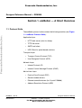
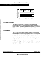
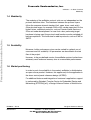
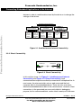
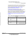
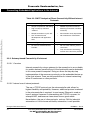
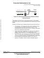
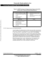
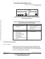
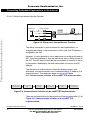
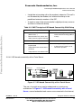
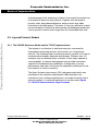
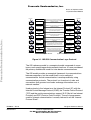
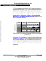

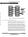
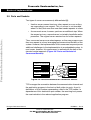
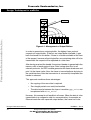
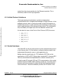
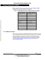

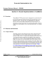

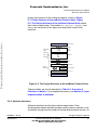
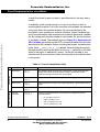
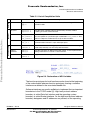
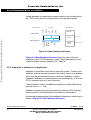
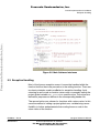
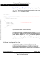
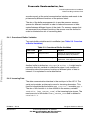
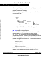
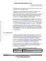
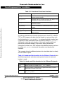

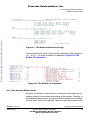
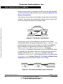

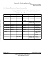
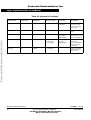
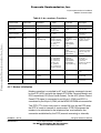
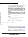
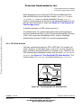
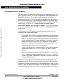
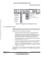

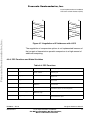
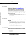
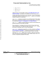
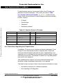
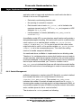


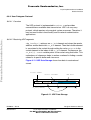
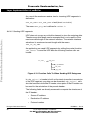
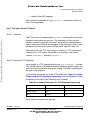

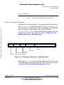
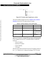
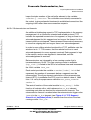
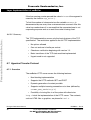
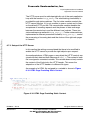


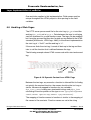
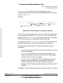
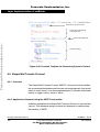
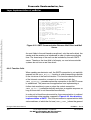
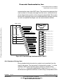
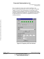

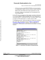

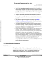

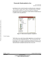


![CardS12 V1.10 Benutzerhandbuch (dt.) [PDF/1187KB]](http://vs1.manualzilla.com/store/data/006794889_1-982c46768f2102028149e2f36e37bced-150x150.png)


![S12compact V1.10 Benutzerhandbuch (dt.) [PDF/1177KB]](http://vs1.manualzilla.com/store/data/006790357_1-164e158d249379663563e4497b227a0b-150x150.png)