1
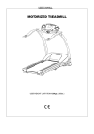
USER’S MANUAL
X-FIT 7 MOTORIZED TREADMILL
MODEL NUMBER: X-FIT 7
USER WEIGHT LIMITATION: 136kgs. (300lbs.)
SERIAL NUMBER (found on frame):
rd
2 Edition
2
X-FIT 7 MOTORIZED TREADMILL
PRECAUTIONS
Precautions:
WARNING: To reduce the risk of burns, fire, electric shock, or injury to persons, read the following important
precautions and information before operating the treadmill. It is the responsibility of the owner to ensure that all
users of this treadmill are adequately informed of all warnings and precautions.
•
Use the treadmill only as described in this manual.
•
Place on a level surface, with 2 meters (6 feet) of clearance behind it. Do not place the treadmill on any
surface that blocks air openings. To protect the floor or carpet from damage, place a mat under the
treadmill.
•
When choosing a location for the treadmill make sure that the location and position permit access to a plug.
•
Keep the treadmill indoors, away from moisture and dust. Do not put the treadmill in a garage or covered
patio, or near water.
•
Do not operate the treadmill where aerosol products are used or where oxygen is being administered.
•
Keep children under the age of 12 and pets away from the treadmill at all times.
•
The treadmill should not be used by persons weighing more than 136kgs. (300lbs.)
•
Never allow more than one person on the treadmill at a time. Wear appropriate exercise clothing when
using the treadmill. Do not wear loose clothing that could become caught in the treadmill. Athletic support
clothes are recommended for both men and women. Always wear athletic shoes. Never use the treadmill
with bare feet, wearing only stockings, or in sandals.
•
When connecting the power cord, plug the power cord into a grounded circuit. No other appliance should
be on the same circuit.
•
Always straddle the belt and allow it to start moving before stepping onto the belt.
•
Always examine your treadmill before using to ensure all parts are in working order.
•
Allow the belt to fully stop before dismounting.
•
Never insert any object or body parts into any opening.
•
Follow the safety information in regards to plugging in your treadmill.
•
Keep the power cord away from the incline wheels and do not run the power cord underneath your treadmill.
Do not operate the treadmill with a damaged or frayed power cord.
•
Always unplug the treadmill before cleaning and/or servicing. Service to your treadmill should only be
performed by an authorized service representative, unless authorized and/or instructed by the
manufacturer. Failure to follow these instructions will void the treadmill warranty.
•
Never leave the treadmill unattended while it is running.
3
X-FIT 7 MOTORIZED TREADMILL
POWER REQUIREMENTS
Power Requirements:
IMPROPER CONNECTION OF THE EQUIPMENT GROUNDING CONNECTOR CAN RESULT IN A RISK OF AN
ELECTRIC SHOCK. CHECK WITH A QUALIFIED ELECTRICIAN OR SERVICE MAN IF YOU ARE IN DOUBT AS
TO WHETHER THE PRODUCT IS PROPERLY GROUNDED. DO NOT MODIFY THE PLUG PROVIDED WITH
THE PRODUCT, IF IT WILL NOT FIT THE OUTLET; HAVE A PROPER OUTLET INSTALLED BY A QUALIFIED
ELECTRICIAN.
This treadmill can be seriously damaged by sudden voltage changes in your home’s electrical power. Voltage
spikes, surges and noise interference can result from weather conditions or from other appliances being turned on or
off. To reduce the possibility of treadmill damage, always use a surge protector (not included) with your treadmill.
Surge protectors can be purchased at most hardware stores. The manufacturer recommends a single outlet surge
protector with a UL 1449 rating as a Transient Voltage Surge Suppressor (TVSS) with a UL suppressed voltage
rating of 400V or less and an electrical rating 120VAC, 15 amps.
This treadmill must be grounded to reduce the risk of electrical shock. Grounding provides a path of least resistance
for electric current, should the treadmill malfunction. This treadmill comes with an electrical cord having an
equipment-grounding conductor and a grounding plug. Always plug the power cord into a surge protector, and plug
the surge protector into an appropriate outlet that is properly installed and grounded in accordance with all local
codes and ordinances.
This product is for use on a nominal 120-volt circuit, and has a grounding plug that looks like the plug illustrated in the
drawing below.
4
X-FIT 7 MOTORIZED TREADMILL
PREASSEMBLY
Open the boxes:
You are now ready to open the boxes of your new equipment. Make sure to inventory all of the parts that are
included in the boxes. Check the Hardware Comparison Chart for a full count of the number of parts included for this
product to be assembled properly. If you are missing any parts or have any assembly questions call the
manufacturer.
Gather your tools:
Before starting the assembly of your unit, make sure that you have gathered all the necessary tools you may require
to assemble the unit properly. Having all of the necessary equipment at hand will save time and make the assembly
quick and hassle-free.
Clear your work area:
Make sure that you have cleared away a large enough space to properly assemble the unit. Make sure the space is
free from anything that may cause injury during assembly. After the unit is fully assembled, make sure there is a
comfortable amount of free area around the unit for unobstructed operation.
Invite a friend:
Some of the assembly steps may require heavy lifting. It is recommended that you obtain the assistance of another
person when assembling this product.
User Weight Limitation:
Please note that there is a weight limitation for this product. If you weigh more than 136kgs (300lbs.) it is not
recommended that you use this product. Serious injury may occur if the user’s weight exceeds the limit
shown here. This product is not intended to support users whose weight exceeds this limit.
5
X-FIT 7 MOTORIZED TREADMILL
HARDWARE COMPARISON CHART
Hardware chart:
For your convenience, we have identified the hardware used in the assembly of this product. This chart is provided to
help you identify those items that may be unfamiliar to you.
NOTE: After assembly there will be a few spare parts (2 part #19 and 4 part #10 pieces) to be used if needed.
NO.
10
DESCRIPTION
M6 x 20mm Allen Head
Bolt
QTY.
4
13
M8 x 10mm Bolt
4
18
#8 x 25mm Screw
14
19
#8 x 19mm Screw
12
27
1/2" x 68mm Bolt
2
28
Plastic Spacer
4
29
M8 x 16mm Allen Bolt
6
30
Upright Support Lock Pin
2
31
M6 x 15mm Allen Head
Screw
2
40
Plastic Cover
2
41
M8 x 25mm Allen Bolt
2
58
M6 x 15mm Phillip Head
Screw
2
A
4mm Allen Wrench
1
B
5mm Allen Wrench
1
C
Wrench
1
D
6mm Allen Wrench
1
MILIMETERS
6
X-FIT 7 MOTORIZED TREADMILL
PARTS LIST
NO.
DESCRIPTION
1
Console
2
ORDER NO.
NO.
DESCRIPTION
1
XFIT7-01
30
2
XFIT7-30
1
XFIT7-02
31
2
XFIT7-31
3
Top Console Housing
Bottom Console
Housing
Upright Support Lock Pin
M6 x 15mm Allen Head
Screw
1
XFIT7-03
32
Left Upright
1
XFIT7-32
4
Bottle Bracket
2
XFIT7-04
33
1
XFIT7-33
5
Decoration Strap
1
XFIT7-05
34
Right Upright
Suspension System
Hardware Assembly
2
XFIT7-34
6
Glove Compartment
1
XFIT7-06
35
7
Safety Key
M4 x 12mm Console
Screw
1
XFIT7-07
36
N/A
Upright Support Tube Upper
2
XFIT7-36
14
XFIT7-08
37
Connector Bolt
2
XFIT7-37
2
XFIT7-09
38
2
XFIT7-38
4
XFIT7-10
39
M12 Nut
Upright Support Tube Bottom
2
XFIT7-39
11
M4 x 12mm Screw
M6 x 20mm Allen
Head Bolt
Console Support
Tube
1
XFIT7-11
40
Plastic Cover
2
XFIT7-40
12
M5 x 12 Screw
3
XFIT7-12
41
M8 x 25 Allen Bolt
2
XFIT7-41
13
4
XFIT7-13
42
M14 x 113 Bolt
2
XFIT7-42
1
XFIT7-14
43
Bushing
4
XFIT7-43
1
XFIT7-15
44
Power Switch Set
1
XFIT7-44
1
XFIT7-16
45
M5 x 10mm Screw
2
XFIT7-45
17
M8 x 10mm Bolt
Handlebar Rear End
Cap - Left #1
Handlebar Rear End
Cap - Left #2
Handlebar Rear End
Cap - Right #2
Handlebar Rear End
Cap - Right #1
1
XFIT7-17
46
1
XFIT7-46
18
#8 x 25mm Screw
16
XFIT7-18
47
Base Frame
Running Deck Fixed
Tube Sleeve
2
XFIT7-47
19
#8 x 19mm Screw
Motion Control
Sensor
14
XFIT7-19
48
Level Adjuster
2
XFIT7-48
2
XFIT7-20
49
Cushion
4
XFIT7-49
2
XFIT7-23
50
6 x 13mm Washer
13
XFIT7-50
24
Hand Pulse Sensor
Handlebar Front End
Cap
2
XFIT7-24
51
51
XFIT7-51
25
M8 x 15mm Screw
2
XFIT7-25
52
1
XFIT7-52
26
#4 x 19 Screw
4
XFIT7-26
53
1
XFIT7-53
27
1/2" x 68mm Bolt
2
XFIT7-27
54
1
XFIT7-54
28
Plastic Spacer
M8 x 16mm Allen
Bolt
4
XFIT7-28
55
#8 x 15mm Screw
Upright Plastic Shroud Left #1
Upright Plastic Shroud Left #2
Upright Plastic Shroud Right #2
Upright Plastic Shroud Right #1
1
XFIT7-55
10
XFIT7-29
56
Side Cover - Left
1
XFIT-56
8
9
10
14
15
16
20
23
29
QTY.
QTY.
ORDER NO.
7
X-FIT 7 MOTORIZED TREADMILL
PARTS LIST
NO.
DESCRIPTION
57
58
Side Cover - Right
M6 x 15mm Phillip
Head Screw
59
ORDER NO.
NO.
DESCRIPTION
1
XFIT7-57
84
Clip
2
XFIT7-84
2
XFIT7-58
85
M10 x 63mm Bolt
1
XFIT7-85
Front Foot Platform
1
XFIT7-59
86
Front Roller
1
XFIT7-86
60
#8 x 50mm Screw
2
XFIT7-60
87
Front Roller Shaft
1
XFIT7-87
61
Motor Hood
1
XFIT7-61
88
Motor Drive Belt
1
XFIT7-88
62
Aluminum Side Rail
2
XFIT7-62
89
M10 x 35mm Bolt
1
XFIT7-89
63
Running Belt
1
XFIT7-63
90
1
XFIT7-90
64
Rear Foot Platform
1
XFIT7-64
91
1
XFIT7-91
65
1
XFIT7-65
92
1
XFIT7-92
1
XFIT7-66
93
Micro Switch
1
XFIT7-93
67
Rubber Spacer - Left
Rubber Spacer Right
Running Deck Rear
Cover
Deck Frame
Motor Hood Side Cover Left
Motor Hood Side Cover Right
1
XFIT7-67
94
M8 x 70mm Bolt
3
XFIT7-94
68
M8 Nut
10
XFIT7-68
95
8
XFIT7-95
69
1
XFIT7-69
96
2
XFIT7-96
70
Running Deck
Deck Rubber
Cushion
10
XFIT7-70
97
M8 x 40mm Bolt
Elevation Support Tube
Clamp - upper
Elevation Support Tube
Clamp - Bottom
2
XFIT7-97
71
Spring Washer
12
XFIT7-71
98
Clamp Bracket
2
XFIT7-98
72
M10 x 15mm Screw
9
XFIT7-72
99
4
XFIT7-99
73
M10 Nylon Nut
5
XFIT7-73
100
1
XFIT7-100
74
Washer
2
XFIT7-74
101
M8 x 25mm Bolt
Deck Frame Side Cover
- Left #1
Deck Frame Side Cover
- Right #1
1
XFIT7-101
75
Rubber Cushion
1
XFIT7-75
102
Rear Roller
1
XFIT7-102
76
M10 x 135mm Bolt
1
XFIT7-76
103
1
XFIT7-103
77
Driving Motor Bracket
1
XFIT7-77
104
1
XFIT7-104
78
8 x 16mm Washer
2
XFIT7-78
105
Rear Roller Shaft
Deck Frame Side Cover
- Left #2
Deck Frame Side Cover
- Right #2
1
XFIT7-105
79
M8 x 15mm Screw
2
XFIT7-79
106
1
XFIT7-106
80
M10 x 136mm Bolt
1
XFIT7-80
107
Rear Frame
Foot Platform Support
Frame
1
XFIT7-107
81
Driving Motor
1
XFIT7-81
108
M8 x 43mm Bolt
2
XFIT7-108
82
Elevation Motor
1
XFIT7-82
109
2
XFIT7-109
83
M5 x 12mm Screw
2
XFIT7-83
110
Wheel
Running Deck Fixed
Tube
1
XFIT7-110
66
QTY.
QTY.
ORDER NO.
8
X-FIT 7 MOTORIZED TREADMILL
PARTS LIST
NO.
DESCRIPTION
111
114
M8 Nylon Nut
Elevation Support
Tube Side Cover Left
Elevation Support
Tube Side Cover Right
Elevation Support
Tube
ORDER NO.
NO.
DESCRIPTION
2
XFIT7-111
138
Transformer
1
XFIT7-112
139
Mat
1
XFIT7-139
1
XFIT7-113
140
Rubber Dot
1
XFIT7-140
1
XFIT7-114
141
Shock Top Cover
2
XFIT7-141
115
Motor Belly Pan
1
XFIT7-115
116
#8 x 35mm Screw
4
XFIT7-116
117
2
XFIT7-117
118
Anti-Static Brush
Brush Fixing Bracket
- Upper
2
XFIT7-118
119
Transport Wheel
2
XFIT7-119
120
2
XFIT7-120
121
M10 x 60mm Bolt
Brush Fixing Bracket
- Bottom
1
XFIT7-121
122
#4 x 19mm screw
6
XFIT7-122
123
M6 x 15 Screw
6
XFIT7-123
124
Spring Washer
6
XFIT7-124
125
4mm Washer
2
XFIT7-125
126
2
XFIT7-126
1
XFIT7-127
1
XFIT7-128
129
Front Handlebar Grip
Emergency Stop Bottom
Emergency Stop Upper
Emergency Stop
Bottom
1
XFIT7-129
130
Front Handlebar
1
XFIT7-130
131
M8 x 15mm Bolt
2
XFIT7-131
132
Handlebar Grip
2
XFIT7-132
133
Handlebar
2
XFIT7-133
134
Steel Sheet
1
XFIT7-134
135
MCB Cooling Fan
1
XFIT7-135
136
Motor Control Board
1
XFIT7-136
137
Transfer Board
1
XFIT7-137
112
113
127
128
QTY.
QTY.
1
ORDER NO.
XFIT7-138
9
X-FIT 7 MOTORIZED TREADMILL
PARTS DIAGRAM
A MAJORITY OF THE PARTS SHOWN HERE HAVE BEEN PREASSEMBLED AT THE FACTORY.
10
X-FIT 7 MOTORIZED TREADMILL
PARTS DIAGRAM
A MAJORITY OF THE PARTS SHOWN HERE HAVE BEEN PREASSEMBLED AT THE FACTORY.
11
X-FIT 7 MOTORIZED TREADMILL
ASSEMBLY
STEP 1:
Remove your treadmill from the carton and place it on the floor in an open area as shown in FIG-1.
Rotate the Left Upright (32) and Right Upright (33) up to the correct position as shown and secure in place using four
M8 x 16mm Allen Bolts (29).
12
X-FIT 7 MOTORIZED TREADMILL
ASSEMBLY
STEP 2:
Remove the four M6 x 20mm Allen Head Bolts (10) from the back of the Bottom Console Housing (3), they have
been preassembled by the factory. Then secure the Bottom Console Housing (3) to the Console Support Tube (11)
using the four M6 x 20mm Allen Head Bolts (10).
13
X-FIT 7 MOTORIZED TREADMILL
ASSEMBLY
STEP 3:
Attach a Plastic Cover (40) to the Left Upright (32) and to the Right Upright (33) then secure each in place using one
M6 x 15mm Phillip Head Screw (58).
14
X-FIT 7 MOTORIZED TREADMILL
ASSEMBLY
STEP 4:
Attach the Upright Support Tube Assembly (36) to the Left Upright (32) and secure with Upright Support Lock Pin
(30) and M6 x 15 Allen Head Screw (31). Repeat the procedure on the Right Upright (33).
Note: Turn the Connector Bolt (37) as shown until fully tightened, turn the M12 Nut (38) as shown until fully
tightened.
15
X-FIT 7 MOTORIZED TREADMILL
ASSEMBLY
STEP 5:
Rotate up the Suspension System Hardware Assembly (34) and secure to the Left Upright (32) using Bolt (27),
Rubber Spacers (28) and Nut (29). Repeat this procedure on the Right Upright (33).
16
X-FIT 7 MOTORIZED TREADMILL
ASSEMBLY
STEP 6:
Remove the M5 x 12 Screw (12) from the Console Support Tube (11) then rotate the Console Support Tube (11) up
to the correct position as shown and secure it in place using the M5 x 12 Screw (12).
Attach the Glove Compartment (6) to the Top Console Housing (2) and secure with M4 x 12mm Console Screw (8).
Place the Mat (139) into the Glove Compartment (6), as shown in FIG 4.
FIG. 4
17
X-FIT 7 MOTORIZED TREADMILL
ASSEMBLY
STEP 7:
Attach the Upright Plastic Shroud - Left #1 (52) to the Upright Plastic Shroud - Left #2 (53) and Left Upright (32) using
six #8 x 25mm Screws (18) and four #8 x 19mm Screws (19).
Attach the Upright Plastic Shroud - Right #1 (55) to the Upright Plastic Shroud - Right #2 (54) and Right Upright (33)
using six #8 x 25mm Screws (18) and four #8 x 19mm Screws (19).
18
X-FIT 7 MOTORIZED TREADMILL
ASSEMBLY
STEP 8:
Connect the two sets of wires between the Handlebar (133) and the Left Upright (32) as shown in FIG 5. Attach the
Handlebar (133) to the Left Upright (32) using two M8 x 10mm Bolts (13).
Repeat this procedure on the other side. Attach the Handlebar (133) to the Right Upright (33)
19
X-FIT 7 MOTORIZED TREADMILL
ASSEMBLY
STEP 9:
Attach the Handlebar Rear End Cap - Left #1 (14) and Handlebar Rear End Cap - Left #2 (15) to the top of the Left
Upright (32) using two #8 x 25mm Screws (18) and two #8 x 19mm Screws (19).
Attach the Handlebar Rear End Cap - Right #2 (16) and Handlebar Rear End Cap - Right #1 (17) to the top of the
Right Upright (33) using two #8 x 25mm Screws (18) and two #8 x 19mm Screws (19).
20
X-FIT 7 MOTORIZED TREADMILL
ASSEMBLY
STEP 11:
Attach the Front Handlebar (130) to the Console Support Tube (11) and secure with two M8 x 25mm Bolts (99).
Your X-Fit 7 treadmill is now fully assembled.
NOTE: Please make sure the Safety Key is inserted (it is located below the Emergency Stop Button), or the treadmill
will not operate.
21
X-FIT 7 MOTORIZED TREADMILL
STABILIZER ADJUSTMENT
How to level the treadmill:
An uneven floor or improper stabilizer level can cause the treadmill to wobble during use as well as the incline
adjustment to function incorrectly. Please follow the procedure described below to make sure the treadmill stabilizer
is adjusted correctly prior to use. You may need the assistance of another person to perform this adjustment.
1.
There are two adjustable stabilizers
and two installed casters located on
the underside of the treadmill as
shown in drawing 1. These all
need to sit firmly on the floor to
prevent the treadmill from wobbling
during use.
2.
Inspect the two stabilizers (one per
side) and two installed casters (one
per side) located underneath the
base frame. The treadmill should
sit with both stabilizers and both
cushions resting firmly on the floor
as shown in drawing 2.
2. Check position of stabilizers and cushions.
3.
Shake the handlebars back and
forth to check if they are resting
firmly on the floor. If they are not,
tilt the treadmill to one side to
adjust the stabilizers as shown in
drawing 3. (You may need the
assistance of another person to
perform this adjustment.) Simply
turn the stabilizers like a screw to
adjust their heights. Repeat this
until the treadmill sits firmly on the
floor.
3. Tilt treadmill to access stabilizers.
22
X-FIT 7 MOTORIZED TREADMILL
TRANSPORTATION INSTRUCTIONS
How to transport your treadmill:
To move your treadmill simply lift the rear of the deck and roll it to the desired location.
23
X-FIT 7 MOTORIZED TREADMILL
MAINTENANCE
How to maintain your treadmill:
Proper maintenance is very important to ensure your treadmill is always in top working condition. Improper
maintenance could cause damage or shorten the life of your treadmill.
•
Important: Never use abrasives or solvents to clean the treadmill. To prevent damage to the computer,
keep liquids away and keep it out of direct sunlight.
•
Inspect and tighten all parts of the treadmill regularly. Replace any worn parts immediately.
BELT ADJUSTMENT:
The running belt has been properly adjusted at the factory. However transportation, uneven flooring or other
unpredicted reasons could cause the belt to shift off center resulting in the belt rubbing with the plastic side rail or end
caps and possibly causing damage. To adjust the belt back to it’s proper position please follow the directions below:
1.
If your belt tends to walk to the right, rotate the right tension bolt clockwise. We recommend adjustments of
1/4 turn at a time, and follow with a test. If your belt continues to walk to the right, simply adjust the left belt
tension bolt by turning it 1/4 turn counterclockwise, and follow with a test.
2.
If your belt tends to walk to the left, rotate the left tension bolt clockwise 1/4 turn at a time, and follow with a
test. If the belt continues to walk to the left, simply adjust the right tension bolt counterclockwise.
3.
If your belt appears to be loose, simply tighten both bolts evenly 1/4 turn. If it appears tight, simply loosen
both bolts evenly 1/4 turn.
Right and left tension bolts are located at the rear of the treadmill.
DECK LUBRICATION:
The walking belt has been pre-lubricated at the factory. However, it is recommended that the walking board be
checked periodically for lubrication to ensure optimal treadmill performance. Your treadmill should not have to be
lubricated usually within the first year or 500 hours of use.
Every 30 days or 30 hours of operation lift the sides of the walking belt and feel the top surface of the walking board
as far as you can reach. If you feel signs of silicone, no further lubrication is required. If it feels dry to the touch,
follow the instructions below.
Please use a non-petroleum based silicone.
24
X-FIT 7 MOTORIZED TREADMILL
MAINTENANCE
To apply lubricant to the walking belt:
1.
Position the walking belt so that the seam is located on top and in center of the walking board.
2.
Insert the spray nozzle into the spray head of the lubricant can.
3.
While lifting the side of the walking belt, position the spray nozzle between the walking belt and the board
approximately 15 cm (6 inches) from the front of the treadmill. Apply the silicone spray to the walking board,
moving from the front of the treadmill to the rear. Repeat this on the other side of the belt. Spray
approximately 4 seconds on each side.
4.
Allow the silicone to "set" for 1 minute before using the treadmill.
Spray lubricant from front to back.
CLEANING:
Routine cleaning of your treadmill will extend the product's life.
•
Warning: To prevent electrical shock, be sure the power to the treadmill is OFF and the power cord is
unplugged from the wall electrical outlet before attempting any cleaning or maintenance.
•
Important: Never use abrasives or solvents to clean the treadmill. To prevent damage to the computer,
keep liquids away and keep it out of direct sunlight.
•
After each workout: Wipe off the console and other treadmill surfaces with a clean, water dampened soft
cloth to remove excess perspiration.
•
Weekly: Use of a treadmill mat is recommended for ease of cleaning. Dirt from your shoes contacts the
belt and eventually makes it to underneath the treadmill. Vacuum underneath treadmill once a week.
25
X-FIT 7 MOTORIZED TREADMILL
IMPORTANT STEPS
Warning:
Before using this product, please consult your personal physician for a complete physical examination. Frequent and
strenuous exercise should be approved by your doctor first. If any discomfort should result from your use of this
product, stop exercising and consult your doctor. Proper usage of this product is essential. Please read your manual
carefully before exercising.
Please keep all children away from the equipment during use and when equipment is unattended.
Always wear appropriate clothing, including athletic shoes, when exercising. Do not wear loose clothing that could
become caught during exercising.
Make sure that all bolts and nuts are tightened when equipment is in use. Periodic maintenance is required on all
exercise equipment to keep it in good condition.
Before beginning:
How you begin your exercise program depends on your physical condition. If you have been inactive for several
years, or are severely overweight, you must start slowly and increase your time gradually, a few minutes per week.
Initially you may be able to exercise only for a few minutes in your target heart rate zone. However, your aerobic
fitness will improve over the next six to eight weeks. Don’t be discouraged if it takes longer. It’s important to work at
your own pace. Ultimately, you’ll be able to exercise continuously for 30 minutes. And the better your aerobic
fitness, the harder you will have to work to stay in your target heart rate zone. But remember these essentials:
•
Contact your physician before starting a workout or training program. Have your doctor review your training
and diet programs to advise you of a workout routine you should adopt.
•
Begin your training program slowly with realistic goals that have been set by you and your doctor.
•
Supplement your program with some type of aerobic exercise such as walking, jogging, swimming, dancing
and/or bicycling. Monitor your pulse frequently. If you do not have an electronic heart rate monitor, have
your physician show you the proper way to manually check your pulse by using your wrist or neck.
Establish your target heart rate based on your age and condition.
•
Drink plenty of fluids during the course of your routine. You must replace the water content lost from
excessive exercising to avoid dehydration. Avoid drinking large amounts of cold liquids. Fluids should be at
room temperature when consumed.
26
X-FIT 7 MOTORIZED TREADMILL
TARGET HEART RATE
Finding your pulse:
To make sure your heart is beating in its target zone, you’ll need to know how to monitor your heart rate. The easiest
way is to feel the pulse in the carotid artery on either side of your neck, between the windpipe and the large neck
muscles. Count the number of beats in ten seconds, and then multiply that number by six. This gives you the
number of beats per minute.
How fast should your heart beat during aerobic exercise? Fast enough to reach and stay in its “target zone,” a range
of beats per minute that is largely determined by your age and physical condition. To determine your target zone,
consult the chart we have provided.
HEART RATE in beats per minute
FIND YOUR TARGET HEART RATE
200
180
160
140
120
100
80
20
25
30
35
40
45
50
55
60
65
70
AGE IN YEARS
ADVANCED: Sports, athletic conditioning or interval training
FITNESS: Optimal training, aerobic or cardiovascular
HEALTH: Beginner, low intensity with long duration produces fat burning
Aerobic exercise:
Is any sustained activity that sends oxygen to your muscles via your heart and lungs. It will improve the fitness of
your lungs and heart: your body’s most important muscle. Aerobic fitness is promoted by any activity that uses your
large muscle groups - arms, legs or buttocks, for example. Your heart beats quickly and you breathe deeply. An
aerobic exercise should be part of your entire exercise routine.
27
X-FIT 7 MOTORIZED TREADMILL
MUSCLE CHART
Targeted muscle groups:
The exercise routine that is performed on this product will develop primarily lower body muscle groups. These
muscle groups are shown in gray color on the chart below.
Shoulder muscles
A
B
Pectoral muscles
Bicep muscle
C
D
Abdominal muscles
Forearm muscles
E
F
Quadricep muscles
Calf muscles
G
H
Trapezius muscles
Tricep muscles
I
J
Back muscles
Gluteal muscles
K
L
Hamstring muscles
28
X-FIT 7 MOTORIZED TREADMILL
STRETCHING ROUTINE
Warm up and cool down:
A successful exercise program consists of a warm-up, aerobic exercise, and a cool-down. Do the entire program at
least two or three times a week, resting for a day between workouts. After several months, you can increase your
workouts to four or five times per week.
Warming up is an important part of your workout, and should begin every session. It prepares your body for more
strenuous exercise by heating up and stretching out your muscles, increasing your circulation and pulse rate, and
delivering more oxygen to your muscles. At the end of your workout, repeat these exercises to reduce sore muscle
problems. We suggest the warm-up and cool-down exercises on the following pages:
Toe Touch:
Slowly bend forward from your waist, letting your back and shoulders relax as you
stretch toward your toes. Reach down as far as you can and hold for 15 counts.
Shoulder Lift:
Lift your right shoulder up toward your ear for one count. Then lift your left
shoulder up for one count as you lower your right shoulder.
Head Roll:
Rotate your head to the right for one count, feeling the stretch up the left side of
your neck. Next, rotate your head back for one count, stretching your chin to the
ceiling and letting your mouth open. Rotate your head to the left for one count,
and finally, drop your head to your chest for one count.
29
X-FIT 7 MOTORIZED TREADMILL
STRETCHING ROUTINE
Hamstring Stretch:
Sit with your right leg extended. Rest the sole of your left foot against
your right inner thigh. Stretch toward your toe as far as possible. Hold
for 15 counts. Relax and then repeat with left leg extended.
Inner Thigh Stretch:
Sit with the soles of your feet together with your knees pointing outward.
Pull your feet as close into your groin as possible. Gently push your
knees towards the floor. Hold for 15 counts.
Side Stretch:
Open your arms to the side and continue lifting them until they are over
your head. Reach your right arm as far upward toward the ceiling as you
can for one count. Feel the stretch up your right side. Repeat this action
with your left arm.
Calf-Achilles Stretch:
Lean against a wall with your left leg in front of the right and your arms
forward. Keep your right leg straight and the left foot on the floor; then
bend the left leg and lean forward by moving your hips toward the wall.
Hold, and then repeat on the other side for 15 counts.
Copyright © 2003