1
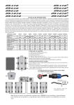
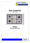
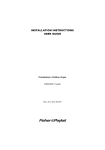
Installation instructions
and User guide
Built-in oven
OB60 single, double, and compact models
NZ AU GB IE SG
Contents
Safety and warnings
Installation instructions
Oven controls and setting the clock
First use
Using your oven
Oven functions
Baking charts
Cooking with ‘auto-off’
Using the timer
Automatic cooking
Care and cleaning
Warranty and service
Important!
SAVE THESE INSTRUCTIONS
The models shown in this user guide may not be available in all markets and are
subject to change at any time. For current details about model and specification
availability in your country, please visit our local website listed on the back cover
or contact your local Fisher & Paykel dealer.
1
2
4
10
14
15
16
18
22
23
24
25
36
2
Safety and warnings
Installation
WARNING!
Electrical Shock Hazard
Always disconnect the appliance from the mains power supply before
carrying out any maintenance or repairs.
Connection to a good earth wiring system is essential and mandatory.
Alterations to the domestic wiring system must only be made by a
qualified electrician.
Failure to follow this advice may result in death or electrical shock.
WARNING!
Fire Hazard
Do not use adapters, reducers, or branching devices to connect this
appliance to the mains power supply.
Failure to follow this advice may result in overheating, burning, or fire.
WARNING!
Cut Hazard
Take care - panel edges are sharp.
Failure to use caution could result in injury or cuts.
Important safety instructions
To avoid hazard, follow these instructions carefully before installing or using this appliance.
Please make this information available to the person installing the appliance - doing so could
reduce your installation costs.
This appliance must be installed and connected to the mains power supply only by a suitably
qualified person according to these installation instructions and in compliance with any
applicable local building and electricity regulations. Failure to install the appliance correctly
could invalidate any warranty or liability claims.
Safety and warnings
3
Operation and maintenance
Your built-in oven has been carefully designed to operate safely during normal cooking
procedures. Please keep the following guidelines in mind when you are using your oven:
WARNING!
Electrical Shock Hazard
Switch the oven off at the wall before any cleaning or maintenance.
Failure to do so may result in death or electrical shock.
WARNING!
Hot Surface Hazard
Accessible parts may become hot when this oven is in use.
To avoid burns and scalds, keep children away.
Do not touch hot surfaces inside the oven.
Use oven mitts or other protection when handling hot surfaces such as oven
shelves or dishes.
Take care when opening the oven door.
Let hot air or steam escape before removing or replacing food.
Failure to follow this advice could result in burns and scalds.
Important safety instructions
Isolating switch: make sure this oven is connected to a circuit which incorporates an isolating
switch providing full disconnection from the power supply.
Household appliances are not intended to be played with by children.
Children, or persons with a disability which limits their ability to use the appliance, should have a
responsible person to instruct them in its use. The instructor should be satisfied that they can use
the appliance without danger to themselves or their surroundings.
Safe food handling: leave food in the oven for as short a time as possible before and after
cooking. This is to avoid contamination by organisms which may cause food poisoning. Take
particular care during warmer weather.
Do not place aluminium foil, dishes, trays, water or ice on the oven floor during cooking as this
will irreversibly damage the enamel.
Do not stand on the door, or place heavy objects on it.
Do not use harsh abrasive cleaners or sharp metal scrapers to clean the oven door glass since
they scratch the surface, which may result in shattering of the glass.
Do not use a steam cleaner to clean any part of the oven.
Caution. Hot air can blow from under the control panel as part of the oven’s cooling system.
Do not keep flammable substances in the oven.
4
Installation instructions
OB60S and OB60N models
I
I
C
E
I
K
B
J J
I
L
D
A
16-20 mm
H
F
L
G
2.5 mm
Installation diagrams for illustration purposes only
Fig. 1 OB60S and OB60N product and cabinetry dimensions
G
H
I
II
J
JI
K
L
overall height* of product
overall width of product
overall depth of product (excluding handle and knobs)
height of chassis
width of chassis
depth of chassis
depth of oven frame and control panel
(=distance between front of chassis and front of oven door, excl. knobs)
depth of oven door when fully open (measured from front of control panel)
minimum inside width of cavity
overall width of cavity
inside height of cavity
overall height of cavity
minimum inside depth of cavity
flush fitting cabinetry clearance
OB60N
A
B
C
D
E
F
OB60S
Product and cabinetry dimensions (mm)
597
595
567
582
556
545
450**
595
556
436
536
532
22
22
435
560
600
585
600
550
22
289
560
600
440**
455**
550
22
Note: If installing a cooktop above the oven, ensure adequate clearance is provided for the
cooktop as per the cooktop manufacturer’s instructions.
*All height measurements include mounted feet.
** If fitting the lower trim extension kit, the overall height of product (A) increases by 25 mm (to 475 mm).
The height of the cavity (J and JI) therefore needs to be increased by 25 mm also (to 465 mm and 480 mm
respectively).
Installation instructions
5
OB60B and OB60D models
I
I
C
I
E
B
J J
A
I
K
L
H
D
16-20 mm
H
I
L
F
G
2.5 mm
Fig. 2 OB60B and OB60D product and cabinetry dimensions
G
overall height* of product
overall width of product
overall depth of product (excluding handle and knobs)
height of chassis
width of chassis
depth of chassis
depth of oven frame and control panel
(=distance between front of chassis and front of oven door, excl. knobs)
H depth of upper oven door when fully open (measured from front of control panel)
HI depth of lower oven door when fully open (measured from front of control panel)
I
minimum inside width of cavity
I
I
overall width of cavity
J
inside height of cavity
overall height of cavity
JI
K
minimum inside depth of cavity
L
flush fitting cabinetry clearance
*All height measurements include mounted feet.
OB60D
A
B
C
D
E
F
OB60B
Product and cabinetry dimensions (mm)
888
595
567
874
556
545
1077
595
567
1057
556
545
22
22
261
435
560
600
877
893
550
22
435
450
560
600
1065
1082
550
22
6
Installation instructions
Before you install the oven, make sure that
the benchtop and oven cavity are square and level, and are the required dimensions
the installation will comply with all clearance requirements and applicable standards and
regulations
a suitable isolating switch providing full disconnection from the mains power supply is
incorporated in the permanent wiring, mounted and positioned to comply with the local wiring
rules and regulations. The isolating switch must be of an approved type and provide a 3 mm air
gap contact separation in all poles (or in all active [phase] conductors if the local wiring rules
allow for this variation of the requirements)
the isolating switch will be easily accessible to the customer with the oven installed
there is at least 1.5 m (and not more than 2 m) free length of power supply cable within the
cavity for ease of installation and servicing
the oven connection socket (if fitted) is outside the cavity if the oven is flush to the rear wall
the oven will rest on a surface that can support its weight
the height from the floor suits the customer
you consult local building authorities and by-laws if in doubt regarding installation.
When you have installed the oven, make sure that
the oven door can open fully without obstruction
the power supply cable does not touch any hot metal parts
the isolating switch is easily accessible by the customer
you complete the ‘Final checklist’ at the end of these installation instructions.
Unpacking the oven
Remove all packaging and dispose of it responsibly. Recycle items that you can.
When you remove the oven from the carton, place it onto wooden blocks or similar supports to
prevent damaging the lower trim.
Important!
Please take extra care not to damage the lower trim of the oven. It is important for correct air circulation
and allows the door to open and close without obstruction. The manufacturer does not accept any
responsibility for damage resulting from incorrect installation.
You may remove the feet but ensure that the oven does not sit on the lower trim.
LOWER TRIM
OVEN DOOR
LOWER TRIM
AIR FLOW
Fig. 3 Correct and incorrect placement of lower trim
Feet
Installation instructions
7
Connecting the oven to the mains power supply
Important!
This oven must be connected to the mains power supply only by a suitably qualified person.
This oven must be earthed.
Before connecting the oven to the mains power supply, check that
the domestic wiring system is suitable for the power drawn by the oven
(as specified on the rating plate)
the voltage corresponds to the value given on the rating plate.
OB60S and OB60N models
OB60B and OB60D models
Model code
Power
Voltage
Model code
Power
Voltage
OB60SL...
2350 - 2550 W
230 - 240 V~
OB60BC...
4400 - 4800 W
230 - 240 V~
OB60SC...
2350 - 2550 W
230 - 240 V~
OB60BD...
4400 - 4800 W
230 - 240 V~
OB60SD...
2350 - 2550 W
230 - 240 V~
OB60B77C...
5850 W
220 - 240 V~
OB60SV...
2350 - 2550 W
230 - 240 V~
OB60B77D...
5850 W
220 - 240 V~
OB60NL...
2050 W
220 - 240 V~
OB60DD...
6120 W
220 - 240 V~
OB60NC...
2800 W
220 - 240 V~
OB60ND...
2800 W
220 - 240 V~
1
Unscrew to
remove cover
plate
1
Unhook to open cover
2
2
L
N
Brown (Live)
Unscrew to open
cable clamp
D
Blue (Neutral)
Green & Yellow
(Earth)
Unscrew to remove
cable clamp
L1
N (L2 )
E
L1 N (L 2)
E
8
Installation instructions
Securing the oven to the cabinetry
1
Position the oven in the prepared cavity.
Important!
2
3
Do not lift the oven by the door handle.
Open the oven door fully.
Use the supplied screws to secure the oven to the cabinetry.
Important!
Do not over-tighten the screws.
Do not seal the oven into the cabinetry with silicone or glue. This makes future servicing difficult.
Fisher & Paykel will not cover the costs of removing the oven, or of damage caused by this
removal.
2.5 mm
Fig. 4 Securing the oven to the cabinetry
Installation instructions
Final checklist
TO BE COMPLETED BY THE INSTALLER
Make sure the oven is level and securely fitted to the cabinetry.
Check the lower trim is still undamaged.
Open the oven door slowly to its fully open position and check if there is adequate clearance
between the bottom of the door and the lower trim. This is to ensure correct air circulation.
Should the lower trim become damaged, straighten the trim and ensure the oven door opens
fully without obstruction.
Turn the power to the oven on. 0.00 will flash in the clock display.
Advise the customer to set the clock and condition the oven, following the instructions under
‘First use’ in the user guide.
Installer’s name:
Installer’s signature:
Installation company:
Date of installation:
LEAVE THESE INSTRUCTIONS WITH THE CUSTOMER
9
MODELS WITH THREE-BUTTON CLOCK
10
Oven controls and setting the clock
Clock display
Control buttons
Temperature
indicator light
Temperature knob
Function
indicator light
Function knob
Fig. 5 Control panel- Compact models with two cooking functions
Temperature
indicator light
Temperature
knob
Clock display
Function
indicator light
Function
knob
Fig. 6 Control panel- Single models with four cooking functions
11
Buttons
sets the clock, shows the time of day when
oven is cooking with ‘auto-off’ set
decreases time and beep volume
increases time
Fig. 7 Clock display and
control buttons
Illuminated symbols
AUTO flashing: oven is ready to be set for cooking
with ‘auto-off’
AUTO steadily lit: oven is cooking with ‘auto-off’ set
To set the clock
1
2
When first connected, or after a power failure, 0.00 will flash in the display.
Press .
Press and until you have the correct time of day.
MODELS WITH THREE-BUTTON CLOCK
Oven controls and setting the clock
12
Oven controls and setting the clock
MODELS WITH SIX-BUTTON CLOCK
Control buttons
Function
indicator light
Temperature
indicator light
Clock display
Temperature knob
Function knob
Fig. 8 Control panel- Compact models with seven cooking functions
Control buttons
Function
indicator light
Temperature
indicator light
Clock display
Temperature knob
Function knob
Fig. 9 Control panel- Single models with seven cooking functions
8
1
7
2
6
3
4
5
Fig. 10 Control panel- Double models with seven-function full oven and two-function compact oven
8
1
7
2
6
3
4
5
Fig. 11 Control panel- Double models with two seven-function ovens (full or compact upper oven)
1
2
3
4
Control buttons
Upper oven function knob
Upper oven temperature knob
Lower oven function knob
5
6
7
8
Lower oven temperature knob
Lower oven temperature indicator light
Upper oven temperature indicator light
Clock display
13
Buttons
sets the timer
sets the cooking time for automatic cooking
sets the stop time for automatic cooking
sets the clock, returns oven to manual mode,
cancels automatic cooking
decreases time and beep volume
increases time
Fig. 12 Clock display and
control buttons
Illuminated symbols
AUTO flashing: oven is ready to be set for automatic cooking
or the clock needs to be set (after a power failure)
AUTO steady lit: oven is set for automatic cooking
timer in operation
AUTO flashing and timer beeping when you have set the stop time for automatic cooking:
program error (The time of day lies between the cooking start and the stop time.)
To set the clock
1
2
When first connected, or after a power failure, 0.00 and AUTO will flash in the display.
Press .
Press and until you have the correct time of day.
MODELS WITH SIX-BUTTON CLOCK
Oven controls and setting the clock
14
1
2
3
4
First use
Before using your new oven, please:
Read this user guide, taking special note of the ‘Safety and warnings’ section.
Remove all accessories and packaging. Make sure you peel the protective film off all surfaces.
Set the clock. The oven will not work until the clock has been set.
See ‘Oven controls and setting the clock’ for instructions.
Condition the oven:
Slide in the shelf/shelves and grill tray as shown in Fig.13 below. Fit them between the
metal wires of the side racks, with the safety stop notch down and at the back.
If you have catalytic panels and sliding shelf supports, make sure these are fitted too.
See ‘Care and cleaning’ for instructions if they are not already fitted.
Heat the oven on maximum temperature for the times below (see ‘Using your oven’):
60 minutes using
30 minutes using
15 minutes using
Note: some of these functions may not be available in some models.
There will be a distinctive smell during the conditioning. This is normal, but make sure your
kitchen is well ventilated.
5
Once cooled, wipe out the oven with a damp cloth and mild detergent, and dry thoroughly.
Shelf positions
4
3
4
3
2
2
1
1
Fig. 13 Correct position of shelves and grill tray - full and compact ovens
Using your oven
15
To start cooking
1
Select the function.
The oven light(s) will come on.
In single and compact models, the function indicator light will also come on.
2
Set the temperature.
The temperature indicator light will come on. It will go out when the oven has reached the
set temperature.
The temperature indicator light may come on and go out again during cooking as the
oven maintains the temperature.
Fig. 14 Turning the function knob
(functions and knobs may vary)
Fig. 15 Turning the temperature knob
(knobs may vary)
When you have finished cooking
Turn both the function and temperature knobs to the off (O) position.
If AUTO is flashing or steadily lit, press
(six-button clock models only).
to return the oven to manual mode
Notes:
Set the temperature back to off (O) before changing functions during cooking.
A cooling fan may automatically come on at different times during cooking and blow out warm
air below the control panel. It may continue to run even after the oven has been turned off. This
is normal.
16
Oven functions
Depending on your model, your may only have some of these functions.
OVEN LAMP
Only the oven light comes on. It remains on in all the cooking functions.
BAKE
This is the traditional method of baking. It is best to bake on only one shelf at a time in this
function. Ideal for large cakes and dishes that bake for several hours.
GRILL
Use with the oven door closed and the temperature set no higher than 225°C. For best results,
use the topmost shelf position when you want quick browning (eg toast).
DEFROST
Only the oven fan comes on. Use with the temperature set to 0. The fan circulates air around the
oven, speeding up the defrosting process by approximately 30%. Note: this function is not for
cooking food.
FAN FORCED
Great for multi-shelf cooking. The consistent temperature ensures baking is well risen. Cookies
are crisp on the outside and chewy in the middle, meat and poultry are deliciously browned and
sizzling while remaining juicy and tender.
FAN GRILL
Use with the oven door closed and the temperature set no higher than 220°C. Ideal for roasting
tender cuts of meat and poultry. Use the lower shelf positions for larger items eg a whole
chicken.
or
WARM
Use this function to keep cooked food hot and to warm plates and serving dishes. To reheat food
from cold, set the temperature to 150°C and reduce it to 70-100°C only when the food is piping
hot. Note: this function is not for cooking food and the temperature cannot be set higher than
150°C.
FAN BAKE
Ideal for dishes like lasagne that need to brown on top and also single trays of small cakes or
biscuits that bake in less than an hour.
Oven functions
17
Important!
Safe food handling: leave food in the oven for as short a time as possible before and after cooking or
defrosting. This is to avoid contamination by organisms which may cause food poisoning. Take particular
care during warmer weather.
Notes on baking:
Preheat the oven before baking.
Do not place anything, including water or ice, on the oven floor.
Remove the fat filter before baking (some models only).
Notes on using the fat filter (some models only):
Use the fat filter only when roasting meat and poultry on FAN BAKE, FAN GRILL or FAN FORCED.
It helps to keep your oven clean and reduces splatter and smoking.
Clean the fat filter after every use. See ‘Care and cleaning’.
Remove the fat filter before baking.
Important!
If the fat filter is not cleaned after every use, the grease build-up will block and shorten the life of the fan
element.
Fig. 16 Fat filter (not supplied with all models)
18
Baking charts
Please note:
The settings in the following charts are guidelines only. Follow the instructions in your recipe or
on packaging and be prepared to adjust the oven settings and baking times to achieve the best
possible results for you.
Shelf positions are counted from the base up (1 is the lowest, 4 the highest).
Arrange oven shelves before you turn the oven on, then preheat the oven to the required
temperature (until the temperature indicator light goes out).
Full ovens are ideal for multi-shelf baking or larger items.
Compact ovens are the ideal and most energy-efficient choice for baking small or flat items (eg
cookies, pizza) on a single shelf; however, they have not been designed for multi-shelf baking.
Settings in bold indicate the recommended oven function.
Baking chart - full ovens
The shelf positions recommended below use the flat oven shelf (not the step-down shelf )
used either with or without sliding shelf supports. Note: the step-down shelf and sliding shelf
supports are not supplied with all models.
BAKE
Food
Small cakes
Scones
Sponge
Light fruit cake
Rich fruit cake
single shelf
Shelf position
Temperature (OC)
Time (mins)
2
180-190
13-17
multi shelf
single shelf
not recommended
2
multi shelf
210-230
8-12
not recommended
two small (20 cm),
staggered on shelf
2
170-190
25-35
one large (26 cm)
2
175
30-40
2
155-165
80-100
exact baking time
2
will depend on size
130-150
3-6 hours
Apple pie
1
185
35-45
Custard tart
1
220, then 180*
10, then 20-30*
* This is a two-stage baking process: adjust the temperature after the first stage.
continued...
Baking charts
Baking chart - full ovens
FAN BAKE
Food
Small cakes
Scones
Sponge
single shelf
Shelf position
Temperature (OC)
Time (mins)
2
150-170
13-17
2
200-220
multi shelf
single shelf
not recommended
multi shelf
8-12
not recommended
two small (20 cm),
staggered on shelf
2
160-175
20-30
one large (26 cm)
2
150
30-40
2
150-160
80-100
Light fruit cake
Rich fruit cake
not recommended
Apple pie
1
Custard tart
160
35-45
not recommended
FAN FORCED
Food
Small cakes
Scones
Sponge
Light fruit cake
Rich fruit cake
Apple pie
Custard tart
Shelf position
Temperature (OC)
Time (mins)
single shelf
2
150-170
13-17
multi shelf
1 and 4**
150-170
15-20
single shelf
2
210-230
8-12
multi shelf
1 and 4**
210-230
10-14
two small (20 cm),
staggered on shelf
2
170-190
25-35
one large (26 cm)
2
175
30-40
2
155-165
80-100
exact baking time
2
will depend on size
130-150
3-6 hours
185
35-45
1
not recommended
** Use the flat shelf in position 1 and the step-down shelf in position 4.
19
20
Baking charts
Baking chart - compact ovens
The shelf positions recommended below use the step-down shelf without sliding shelf supports.
BAKE
Food
Shelf position
Temperature (OC)
Time (mins)
Small cakes
2
180-190
13-17
Scones
Sponge
Light fruit cake
Rich fruit cake
2
210-230
8-12
two small (20 cm),
staggered on shelf
2
170-190
25-35
one large (26 cm)
2
175
30-40
2
155-165
80-100
exact baking time
2
will depend on size
130-150
3-6 hours
Apple pie
1
185
35-45
Custard tart
1
220, then 180*
10, then 20-30*
* This is a two-stage baking process: adjust the temperature after the first stage.
continued...
Baking charts
Baking chart - compact ovens
FAN BAKE
Food
Shelf position
Temperature (OC)
Time (mins)
Small cakes
2
150-170
13-17
Scones
Sponge
3
200-220
8-12
two small (20 cm),
staggered on shelf
2
160-175
20-30
one large (26 cm)
2
150
30-40
2
150-160
80-100
Light fruit cake
Rich fruit cake
not recommended
Apple pie
1
Custard tart
160
35-45
not recommended
FAN FORCED
Food
Shelf position
Temperature (OC)
Time (mins)
Small cakes
2
150-170
13-17
Scones
2
210-230
8-12
two small (20 cm),
staggered on shelf
2
170-190
25-35
one large (26 cm)
2
175
30-40
2
150-160
80-100
exact baking time
2
will depend on size
130-150
3-6 hours
185
35-45
Sponge
Light fruit cake
Rich fruit cake
Apple pie
Custard tart
1
not recommended
21
MODELS WITH THREE-BUTTON CLOCK
22
Cooking with ‘auto-off ’
Use ‘auto-off’ to automatically turn the oven off
when the set cooking time has elapsed.
To set the oven for cooking with ‘auto-off’
1
2
Set the oven:
Check the clock shows the correct time (eg 12:07).
Select the function and set the temperature.
The oven will turn on.
Fig. 17 Three-button clock display
and control buttons
Set the cooking time:
Decide how long the food will take to cook,
allowing time for preheating if necessary
(eg 40 minutes).
Press
.
While AUTO is flashing, use and to set the cooking time (eg 40 minutes).
Notes on setting the cooking time
If the cooking time is 99 minutes or less:
you can set it in 10-second steps
the remaining time will count down in seconds (min.sec).
If the cooking time is 100 minutes (ie 1 hour 40 minutes) or more:
you can set it in 1-minute steps
the remaining time will start counting down in minutes (h.min).
When ‘auto-off’ is set
The time will start counting down and the clock display will show the remaining time with AUTO
steadily lit.
To see the current time of day, press
.
To cancel the ‘auto-off’ setting, press and together. The current time of day will appear in
the display. Turn the function and temperature knobs to O (off ).
When the cooking time is over
The oven will automatically turn off (eg at 12:47). AUTO will start flashing, the current time of day
will appear in the display and the timer will beep:
1
2
Press any button to stop the beeping and return the oven to manual mode.
Turn the function and temperature knobs to O (off ).
23
You can use the timer at any time, even when
the oven is not in use.
Important!
The timer does NOT turn the oven off.
To set the timer
1
2
Press . 0.00 will show and the
symbol
will start flashing.
Press and to set the time you want (up to 23 hours
and 59 minutes, in 1-minute steps).
After a few seconds, the clock will show the
time of day with the
symbol steadily lit.
The timer is now counting down.
Fig. 18 Six-button clock display
and control buttons
To check the remaining time
Press
.
To cancel the timer
1
2
Press .
Press until the time is reset to 0.00
After a few seconds, the clock will show the time of day.
When the set time is up
The timer will beep and the
symbol will flash. Press
to stop the beeping and turn the timer
off.
After a few seconds, the clock will show the time of day.
To adjust the beep volume
Press
to hear the next volume level. The last one selected will be stored.
MODELS WITH SIX-BUTTON CLOCK
Using the timer
MODELS WITH SIX-BUTTON CLOCK
24
Automatic cooking
Important!
In double models with compact upper ovens,
only the lower (main) oven can
be set for automatic cooking.
In double models with two full ovens,
only the upper oven can be set for automatic cooking.
To set the oven for automatic cooking
1
Fig. 19 Six-button clock display
Set the oven:
and control buttons
Check the clock shows the correct time (eg 12:07).
Select the function and set the temperature. The oven will turn on.
2
Set the cooking time:
Decide how long the food will take to cook, allowing time for preheating if necessary
(eg 40 minutes).
Press
.
Use and to set the cooking time. AUTO will show in the display.
3
Set the stop time:
Decide when you want your food to be ready by (eg 13:30).
Press .
Use and to set the stop time.
You can turn the oven on manually and set it to turn off automatically by setting the stop time
(step 3 above).
When automatic cooking is set
If there is time before cooking starts, the oven will turn off and the current time of day and AUTO
will show in the clock display, indicating that the oven is set for automatic cooking. Note: the
cooling fan may stay on.
The oven will automatically turn on at the required time (eg 12:50) and turn off at the set stop
time (eg 13:30).
To see the remaining cooking time, press
.
To see the set stop time, press
.
To cancel automatic cooking, press
and turn the function and temperature knobs to 0 (off ).
When the stop time is reached
The oven will turn off, the timer will beep and AUTO will flash.
1
2
Press to stop the beeping and return the oven to manual mode.
Turn the function and temperature knobs to O (off ).
Care and cleaning
25
Important!
Always switch the power to the oven off at the wall before any cleaning or maintenance.
When you switch the power back on after cleaning, you will have to set the clock.
Do not use abrasive cleaners, cloths or pads to clean any part of your oven. Some nylon scourers
may also scratch. Check the label.
See the following pages for instructions on removing and refitting different parts of the oven for
cleaning.
Before cleaning, make sure the oven is a safe temperature to touch.
Do not use a steam cleaner.
What?
How?
General advice
Stainless steel
surfaces
Wipe out the oven after every
use.
Wipe up spills as soon as the
oven is a safe temperature to
touch.
1
2
3
Wipe the soiling off with a
cloth using a mild household
detergent or stainless steel
cleaner.
Wipe the surface dry.
Use a suitable stainless steel
polish.
Glass surfaces
Wipe with a damp cloth or use a
glass cleaner.
Oven cavity
(enamel)
1
2
3
4
Side racks, oven
shelves, trays
Remove everything from the
oven: all shelves and trays, the
side racks and the catalytic
panels and fat filter if supplied.
Remove the oven door (see
instructions on following
pages).
Wipe the inside of the oven
using a household detergents
or an ammonia-based cleaner.
Wipe clean with a damp cloth
and allow to dry completely.
Clean these using a solution of
detergent and hot water. They
are also dishwasher safe.
If badly soiled, soak in a solution
of hot water and biological
clothes washing powder to
make cleaning easier.
Important!
Avoid leaving alkaline or acidic
substances (such as lemon juice,
vinegar or salty spills) on the oven
surfaces.
Do not use cleaning products with
a chlorine or acidic base.
Immediately wipe off any caustic
cleaners if they are spilled onto
the oven door handle or the knobs.
Do not use harsh abrasive cleaners
or sharp metal scrapers since they
scratch the surface and may result
in the glass shattering.
To make cleaning easier, the grill
element in some ovens drops
down after you have removed the
side racks.
If using ‘off the shelf’ oven
cleaners, always follow the
manufacturer’s instructions.
26
Care and cleaning
What?
How?
Important!
Side catalytic
panels
(not supplied with
all models)
Either remove the side racks and
reverse the panels or heat the oven
at 250oC on
for 60-90 minutes
and they will self-clean.
These panels absorb and eliminate
greasy splashes at high-temperature
cooking. They do not normally require
cleaning. Clean only if they remain
dirty after you have cooked very fatty
foods.
Sliding shelf
supports (not
supplied with all
models)
Wipe with a damp cloth and mild
detergent. Do not wipe off or wash
away the white lubricating grease
(visible when the slides are
extended).
Do not wash these in the dishwasher,
immerse in soapy water, or use oven
cleaner on them as doing so will
remove the white lubricating grease
and prevent the slides from running
smoothly.
Fat filter
(not supplied with
all models)
If lightly soiled: wash in
dishwasher (normal cycle).
If heavily soiled:
Place under water in a pan.
Add two tablespoons of clothes
washing powder.
Bring to the boil.
Leave to soak for 30 minutes.
Rinse in clean water and dry.
Clean after every use. If the filter is not
cleaned, the grease build-up will block
and shorten the life of the fan element.
Rubber seal framing
the oven cavity
Wipe very gently with a damp cloth
and mild detergent.
Take care not to unhook and
displace the rubber seal while
cleaning it.
Take care not to spray any oven
cleaner or other caustic cleaner on
the rubber seal, as doing so may
damage the rubber.
Knobs
1
1
2
3
4
5
2
Wipe with a damp cloth and
Do not use stainless steel or oven
mild detergent.
cleaner on the knobs, as doing so may
Dry thoroughly with a soft cloth. damage their coating.
Care and cleaning
27
Removing and refitting the side racks and catalytic panels
Note: only some models have catalytic panels and a lamp in the left oven wall.
Fig.20a Side rack and catalytic panel in full oven cavity
Fig.20b Side rack in compact oven cavity
When refitting the side racks, make sure they are the right way up, as in the illustrations.
When refitting the catalytic panels, make sure that:
the arrows are pointing upwards
the panel with the hole is on the left oven wall (if there is a lamp in the wall).
Note: in some models, the back of the oven is also a catalytic panel, but this is not reversible and
should not be removed.
Drop-down grill element (some models)
Once you have removed the side racks, the grill element in some full ovens drops down (Fig. 21)
The grill element itself is self-cleaning. Note: some grill elements are fixed.
Fig.21 Drop-down grill element
28
Care and cleaning
Removing and refitting the sliding shelf supports (some models only)
Important!
Remove the side racks first to make removing the sliding shelf supports easier.
When refitting the sliding shelf supports, make sure that you fit
the side racks first
the slides to the top wire of a shelf position. They do not fit on the lower wire
both sides of each pair of slides
both slides on the same level.
Notes:
In some full ovens, you cannot fit the slides to the topmost shelf position.
In a compact oven, you can only fit the slides on the wire immediately below the side rack fixing
screws.
Clip on
1
Unclip
2
1
Fig.22 Removing the sliding shelf supports
Fig.23 Refitting the sliding shelf
supports - full oven cavity
Care and cleaning
Removing and refitting the glass panes of the oven door
Important!
Oven doors vary. Some have three glass panes, others only two.
The outer pane is not removable.
Take care, the glass panes are heavy.
Place the removed glass panes on a safe, soft surface.
To remove the glass panes
1
Open the door fully.
2
Open the levers.
3
Close door until the levers hook
to the door.
4
Remove seal (some doors only).
Lever
Seal
Hook into
29
30
Care and cleaning
....then depending on your model...
MODELS WITH INNER PANE ONLY
5
Slide out the inner pane.
MODELS WITH INNER AND MIDDLE PANES
5
Slide out the inner pane.
6
Slide the middle pane up slightly
to unhook it from the bottom
clamps.
7
Lift out the bottom edge and
remove.
1
2
Care and cleaning
31
To refit the glass panes
MODELS WITH INNER PANE ONLY
MODELS WITH INNER AND MIDDLE PANES
1
Make sure the open levers firmly
hook to the door.
1
Make sure the open levers firmly
hook to the door.
2
Check the rubber pads are in place.
2
Check the rubber pads are in place.
Rubber pads
3
Rubber pads
Check the pane is the right way up.
3
1
Check the pane is the right way up.
1
cont....
32
Care and cleaning
MODELS WITH INNER PANE ONLY
4
Insert the pane into the slide guides
and slide it to the bottom retainers.
MODELS WITH INNER AND MIDDLE PANES
4
Insert the pane into top clamps then
lower and slide into bottom clamps.
Slide guides
3
F
Bottom
retainers
1
2
1
5
Replace the seal (some doors only).
5
Check the rubber pads are in place.
Seal
Rubber pads
6
6
Check the pane is the right way up.
Open the door fully and close the
levers.
Lever
1
cont....
Care and cleaning
MODELS WITH INNER PANE ONLY
33
MODELS WITH INNER AND MIDDLE PANES
7
Insert the pane into the slide guides
and slide it to the bottom retainers.
Slide guides
F
Bottom
retainers
8
Replace the seal (some doors only).
Seal
9
Open the door fully and close the
levers.
Lever
Care and cleaning
34
Removing and refitting the oven door
Important!
Take care, the oven door is heavy!
To remove the door
1
Open the door fully.
2
Open the levers.
4
Close the door until the levers
hook to it.
5
Disengage the hinges and
remove the door.
Lever
Hook into
3
C
Hold the door.
To refit the door
Repeat these steps in reverse order.
Care and cleaning
35
Replacing the oven lamp
Note: oven bulb replacement is not covered by your warranty.
1
2
Let the oven cavity and the grill element cool down.
Switch the power to the oven off at the wall.
LEFT LAMP (some models only)
3a Remove the left side rack (and catalytic panel if supplied). See ‘Removing and refitting the side
racks and catalytic panels’.
4a Press down on the lamp cover and rotate to remove.
Important!
Never use screwdrivers or other utensils to remove the lamp cover, as doing so could damage the
surrounding enamel. Only use your hands.
5a Unscrew and replace the bulb with a new one suitable for high temperatures (300oC) with the
following specifications: 230-240V, 50Hz, E14 and same wattage as the bulb being replaced
(check wattage stamped on the bulb).
6a Refit the lamp cover, operating in reverse order. Make sure that it clicks into place.
Important!
The notch in the inner edge of the cover must be on the side closer to the back of the oven.
7a Refit the left side rack (and the left catalytic panel if supplied).
8a Switch the power to the oven back on at the wall.
TOP RIGHT LAMP
3b Twist the lamp cover off.
4b Unscrew and replace the bulb with a new one suitable for high temperatures (300oC) with the
following specifications: 230-240V, 50Hz, E14 and same wattage as the bulb being replaced
(check wattage stamped on the bulb).
5b Twist the lamp cover back on.
6b Switch the power to the oven back on at the wall.
1
2
LEFT LAMP (some models only)
Fig.24 Removing the oven lamps
36
Warranty and service
Before you call for service or assistance ...
Check the things you can do yourself. Refer to the installation instructions and your user guide
and check that:
1
2
your product is correctly installed.
you are familiar with its normal operation.
If after checking these points you still need assistance or parts, please refer to the Service &
Warranty book for warranty details and your nearest Authorised Service Centre, or contact us
through our local website listed on the back cover:
This oven has been designed and constructed in accordance with the following
codes and specifications:
In New Zealand and Australia:
AS/NZS 60335-1 General Requirements for Domestic electrical appliances
AS/NZS 60335-2-6 Particular Requirements for Domestic electrical cooking appliances
AS/NZS 1044 Electromagnetic Compatibility Requirements.
In Europe:
Safety requirements of EEC Directive “Low voltage” 2006/95:
- EN 60335-1 General Requirements for Domestic electrical appliances
- EN 60335-2-6 Particular Requirements for Domestic electrical cooking appliances
Safety requirements of EEC Directive “EMC” 89/336:
- EN 55014-1, EN 55014-2, EN 61000-3-2, EN 61000-3-3 Electromagnetic Compatibility
Requirements
Requirements of EEC Directive 93/68.
European directive 2002/96/EC on Waste Electrical and Electronic Equipment (WEEE)
(for European Union countries only)
GB This appliance is marked according to the European directive 2002/96/EC on Waste Electrical
and Electronic Equipment (WEEE). By ensuring this product is disposed of correctly, you will help
prevent potential negative consequences for the environment and human health, which could
otherwise be caused by inappropriate waste handling of this product.
The symbol
on the product, or on the documents accompanying the product, indicates that
this appliance may not be treated as household waste. Instead it shall be handed over to the
applicable collection point for the recycling of electrical and electronic equipment. Disposal
must be carried out in accordance with local environmental regulations for waste disposal.
For more detailed information about treatment, recovery and recycling of this product, please
contact your local city office, your household waste disposal service or the shop where you
purchased the product.
Copyright © Fisher & Paykel 2008. All rights reserved.
The product specifications in this booklet apply to
the specific products and models described at the
date of issue. Under our policy of continuous product
improvement, these specifications may change at any
time. You should therefore check with your Dealer to
ensure this booklet correctly describes the product
currently available.
www.fisherpaykel.co.nz
www.fisherpaykel.com.au
www.fisherpaykel.co.uk
www.fisherpaykel.ie
www.fisherpaykel.com.sg
NZ AU GB IE SG
Built-in oven user guide
Published: 12/2008
Part No. 599606 B
F&P Italy Part No. 1103204 - ß2